EP0228263B1 - Système de commande pour transmission continue de vitesse - Google Patents
Système de commande pour transmission continue de vitesse Download PDFInfo
- Publication number
- EP0228263B1 EP0228263B1 EP86309966A EP86309966A EP0228263B1 EP 0228263 B1 EP0228263 B1 EP 0228263B1 EP 86309966 A EP86309966 A EP 86309966A EP 86309966 A EP86309966 A EP 86309966A EP 0228263 B1 EP0228263 B1 EP 0228263B1
- Authority
- EP
- European Patent Office
- Prior art keywords
- signal
- transmission ratio
- load
- transmission
- engine
- Prior art date
- Legal status (The legal status is an assumption and is not a legal conclusion. Google has not performed a legal analysis and makes no representation as to the accuracy of the status listed.)
- Expired - Lifetime
Links
- 230000005540 biological transmission Effects 0.000 title claims description 65
- 230000005856 abnormality Effects 0.000 claims description 6
- 230000001133 acceleration Effects 0.000 description 4
- 230000000994 depressogenic effect Effects 0.000 description 4
- 230000007257 malfunction Effects 0.000 description 4
- 238000010586 diagram Methods 0.000 description 2
- 230000033001 locomotion Effects 0.000 description 2
- 230000007935 neutral effect Effects 0.000 description 2
- 230000002159 abnormal effect Effects 0.000 description 1
- 238000010276 construction Methods 0.000 description 1
- 230000003247 decreasing effect Effects 0.000 description 1
- 230000002950 deficient Effects 0.000 description 1
- 239000000843 powder Substances 0.000 description 1
Images


Classifications
-
- F—MECHANICAL ENGINEERING; LIGHTING; HEATING; WEAPONS; BLASTING
- F16—ENGINEERING ELEMENTS AND UNITS; GENERAL MEASURES FOR PRODUCING AND MAINTAINING EFFECTIVE FUNCTIONING OF MACHINES OR INSTALLATIONS; THERMAL INSULATION IN GENERAL
- F16H—GEARING
- F16H61/00—Control functions within control units of change-speed- or reversing-gearings for conveying rotary motion ; Control of exclusively fluid gearing, friction gearing, gearings with endless flexible members or other particular types of gearing
- F16H61/66—Control functions within control units of change-speed- or reversing-gearings for conveying rotary motion ; Control of exclusively fluid gearing, friction gearing, gearings with endless flexible members or other particular types of gearing specially adapted for continuously variable gearings
- F16H61/662—Control functions within control units of change-speed- or reversing-gearings for conveying rotary motion ; Control of exclusively fluid gearing, friction gearing, gearings with endless flexible members or other particular types of gearing specially adapted for continuously variable gearings with endless flexible members
- F16H61/66254—Control functions within control units of change-speed- or reversing-gearings for conveying rotary motion ; Control of exclusively fluid gearing, friction gearing, gearings with endless flexible members or other particular types of gearing specially adapted for continuously variable gearings with endless flexible members controlling of shifting being influenced by a signal derived from the engine and the main coupling
- F16H61/66259—Control functions within control units of change-speed- or reversing-gearings for conveying rotary motion ; Control of exclusively fluid gearing, friction gearing, gearings with endless flexible members or other particular types of gearing specially adapted for continuously variable gearings with endless flexible members controlling of shifting being influenced by a signal derived from the engine and the main coupling using electrical or electronical sensing or control means
-
- F—MECHANICAL ENGINEERING; LIGHTING; HEATING; WEAPONS; BLASTING
- F16—ENGINEERING ELEMENTS AND UNITS; GENERAL MEASURES FOR PRODUCING AND MAINTAINING EFFECTIVE FUNCTIONING OF MACHINES OR INSTALLATIONS; THERMAL INSULATION IN GENERAL
- F16H—GEARING
- F16H61/00—Control functions within control units of change-speed- or reversing-gearings for conveying rotary motion ; Control of exclusively fluid gearing, friction gearing, gearings with endless flexible members or other particular types of gearing
- F16H61/12—Detecting malfunction or potential malfunction, e.g. fail safe; Circumventing or fixing failures
-
- Y—GENERAL TAGGING OF NEW TECHNOLOGICAL DEVELOPMENTS; GENERAL TAGGING OF CROSS-SECTIONAL TECHNOLOGIES SPANNING OVER SEVERAL SECTIONS OF THE IPC; TECHNICAL SUBJECTS COVERED BY FORMER USPC CROSS-REFERENCE ART COLLECTIONS [XRACs] AND DIGESTS
- Y10—TECHNICAL SUBJECTS COVERED BY FORMER USPC
- Y10S—TECHNICAL SUBJECTS COVERED BY FORMER USPC CROSS-REFERENCE ART COLLECTIONS [XRACs] AND DIGESTS
- Y10S477/00—Interrelated power delivery controls, including engine control
- Y10S477/906—Means detecting or ameliorating the effects of malfunction or potential malfunction
Definitions
- the present invention relates to a control system for a continuously variable belt-drive automatic transmission for a motor vehicle, as defined in the first part of claim 1.
- Such a known continuously variable belt-drive transmission for a motor vehicle (GB-A-2 145 275) operates to decide the transmission ratio in accordance with the opening degree of a throttle valve of an engine and the speed of the engine.
- the line pressure control valve is adapted to control the line pressure in accordance with the transmission ratio and the engine speed.
- the line pressure is control led to prevent the belt from slipping on the pulleys in order to transmit the output of the engine.
- Japanese Patent Application Laid Open 59-77 157 discloses a fail-safe system for a continuously variable transmission.
- the system is adapted to set itself to the maximum transmission ratio when the electromagnetic clutch, which transmits the output of the engine to the transmission, is disengaged. Accordingly, even if the throttle position sensor fails to sense the load on the engine, the vehicle can be started at the maximum transmission ratio. However, the transmission ratio is not properly controlled after the starting of the vehicle.
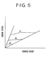
- the throttle position sensor In the event of malfunction of the throttle position sensor, it may generate an erroneous signal representing either the wide-open throttle position, or the closed throttle position.
- the transmission ratio changes along a line 11 of Figure 5. As seen from the figure, the ratio varies in a high engine speed range.
- the transmission ratio changes along a line 1 2 in a low engine speed range. Accordingly, if, for example, the engine is accelerated on an uphill road, the transmission ratio is up-shifted along the line 2 in the low en. gine speed range. In such driving conditions, since the driving torque of the engine is very low, it is difficult to drive the vehicle.
- the present invention seeks to provide a fail-safe system which may control the transmission ratio so as to prevent the reduction of the driveability of a vehicle during malfunctions of a load sensor of an engine.
- the system of the present invention includes a throttle position sensor for detecting the load of an engine and for deciding the transmission ratio in accordance with the load. Abnormality of the throttle position sensor is detected by comparing a first load signal immediately after starting of the engine with a subsequent load signal. When difference between the first load signal and the subsequent load signal is smaller than a predetermined value, a fail-safe signal is produced for maintaining the transmission ratio at a moderate value.
- a control system for a continuously variable transmission for a motor vehicle as defined in claim 1.
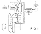
- a motor vehicle is provided with an engine 1, and an electromagnetic powder clutch 2 for transmitting the power of the engine to a continuously variable belt-drive transmission 4 through a selector mechanism 3.
- the beft-drive transmission 4 has a main shaft 5 and an output shaft 6 provided in parallel with the main shaft 5.
- a drive pulley (primary pulley) 7 and a driven pulley (secondary pulley) 8 are mounted on shafts 5 and 6 respectively.
- a fixed conical disc 7b of the drive pulley 7 is integral with main shaft 5 and an axially movable conical disc 7a is axially slidably mounted on the main shaft 5.
- the movable conical disc 7a also slides in a cylinder 9a formed on the main shaft 5 to provide a servo device.
- a chamber 9 of the servo device communicates with a hydraulic circuit 20.
- a fixed conical disc 8b of the driven pulley 8 is formed on the output shaft 6 opposite a movable conical disc 8a.
- the conical disc 8a has a cylindrical portion which is slidably engaged in a cylinder 6a of the output shaft 6 to form a servo device.
- a chamber 10 of the servo device is also communicated with hydraulic circuit 20.
- a drive belt 11 engages with the drive pulley 7 and the driven pulley 8.
- a drive gear 12 Secured to the output shaft 6 is a drive gear 12 which engages with an intermediate reduction gear 13 on an intermediate shaft 14.
- An intermediate gear 15 on the shaft 14 engages with a final gear 16.
- the rotation of the final gear 16 is transmitted to axles 18 of vehicle driving wheels 19 through a differential 17.
- chamber 9 of the drive pulley 7 is supplied with pressurized oil by an oil pump 21 from an oil reservoir 26 passing through a line pressure conduit 22, ports 41 a and 41 e of a line pressure control valve 40, transmission ratio control valve 50. and conduit 23.
- the chamber 10 of driven pulley 8 is supplied with pressurized oil through a passage 22b without passing through valves 40 and 50.
- the movable conical disc 7a of the drive pulley 7 is so designed that the pressure receiving area thereof is larger than that of movable conical disc 8a of the driven pulley 8.
- the line pressure control valve 40 comprises a valve body 41, spool 42, and chambers 41 c and 41 d.
- the spool 42 is supplied with pressure of the pressurized oil in the chamber 41 c, supplied through a conduit 31.
- the other end of the spool 42 is engaged with a spring 43 provided between the end of the spool 42 and a retainer 45 the position of which is adjustable by a screw 44.
- the port 41 a communicates with a drain port 41 b for a drain passage 27 in accordance with the position of a land of the spool 42.
- the drain port 41 b communicates with oil reservoir 26 through passage 27.
- the transmission ratio control valve 50 comprises a valve body 51, spool 52, and a spring 53 for urging the spool 52 in the downshift direction.
- a port 51 of the valve body 51 is selectively connected with a pressure oil supply port 51 a or a drain port 51c in accordance with the position of lands of spool 52.
- Port 51b communicates with chamber 9 through conduit 23, and port 51 a communicates with port 41 e of line pressure control valve 40 through a conduit 22a.
- the drain port 51c communicates with the oil reservoir 26 through a conduit 24 and a check valve 25.
- the system is provided with a regulator valve 60, and solenoid operated on-off control valves 66 and 68.
- the regulator valve 60 comprises a valve body 61, an inlet port 61 a connected to the pump 21 through passages 37 and 22, a spool 62, an end chamber 61c connected to the passage 37, and a spring 63 urging the spool 62 to the chamber 61c.
- the passage 37 communicates with the chamber 41d of line pressure control valve 40 through a constant pressure passage 38, orifice 65, solenoid operated on-off valve 66, and a passage 32 having an accumulator 32a. Further, the passage 38 is communicated with an end chamber 51 d of the transmission ratio control valve 50 through a passage 33, and with another end chamber 51e through a passage 34, orifice 67, and solenoid operated on-off valve 68.
- the solenoid operated on-off valve 66 is adapted to be operated by pulses. When energized, a valve element 66a opens a drain port 66b. Variations of the pressure of oil In the passage 32 are smoothed by accumulator 32a.
- the solenoid operated on-off valve 68 is the same as valve 66 In construction and operation.
- the control valves 66 and 68 are operated by signals from a control unit 70.
- oil pressure controlled by the control valves 66 and 68 is applied to chambers 41d and 51 e.
- the transmission ratio control valve 50 pressure receiving area of the spool 52 at chamber 51e Is set to a value larger than the area at the chamber 51 d.
- the control pressure in the chamber 51e can be changed between a maximum value, which is the same as the constant pressure in the chamber 51d, when the duty ratio is 0 % and zero by controlling the duty ratio of pulses for operating the control valve 68.
- the transmission ratio control valve 50 is so arranged that the spool 52 is at a neutral position at a middle duty ratio (for example 50 %) and is located in an oil supply position by increasing the duty ratio from the middle duty ratio because of reduction of control pressure in the chamber 51 e. Further, the speed of the movement of the spool 52 changes with the rate of change of the duty ratio.
- the spool 52 is shifted to an oil drain position by decreasing the duty ratio. It will be understood that when the oil is supplied to the chamber 9, the transmission is upshifted.
- a drive pulley speed sensor 71, driven pulley speed sensor 72, engine speed sensor 73 and throttle position sensor (or Intake manifold pressure sensor) as a load sensor 74 are provided.
- Output signal Ns and output signal 9 of the throttle position sensor 74 are fed to a desired transmission ratio calculating means (table) 76.
- the desired transmission ratio id is fetched by the table 76 in accordance with the signals N s and ⁇ .
- the output signal 9 is fed to an acceleration calculator 82 to obtain acceleration ⁇ .
- the signal of the acceleration ⁇ is supplied to a coefficient setting section 77 to produce a coefficient K.
- the speed di/dt and actual ratio I are applied to a duty ratio table 79 to derive the duty ratio D.
- the duty ratio D is supplied to the solenoid operated valve 68 through a driver 80.
- the actual transmission ratio from the calculator 75 is applied to a necessary line pressure table 103 to derive a necessary line pressure Pw per unit torque.
- the necessary line pressure P LU and the engine torque T are applied to a desired line pressure calculator 104 where a desired line pressure P L is calculated.
- the duty ratio D L is supplied to a driver 106 which operates the solenoid operated on-off valve 66 at the duty ratio.
- the signal 6 of throttle position sensor 74 is supplied to an abnormality detector 107.
- the detector 107 detects an abnormality of output of the throttle position sensor 74 in the following way: Immediately after the starting of the engine, the accelerator pedal of the vehicle is not normally depressed, The output of the throttle position sensor 74 changes when the accelerator pedal is depressed in order to set the vehicle into motion. Accordingly, if the magnitude of output signal does not change when the vehicle is started, this indicates that the throttle position sensor 74 is not operating normally.
- the detector 107 When the abnormality is detected, the detector 107 produces first and second fail-safe throttle position signals.
- the first fail-sate signal is provided for the desired transmission ratio and set to a predetermined value, for example a value corresponding to 60 % of the value 6 at the full throttle open.
- the second fail-safe signal is provided for the desired line pressure and set to a value corresponding to 100 % of a maximum engine torque.
- the first fail-safe signal is applied to the desired transmission ratio table 76 to produce a predetermined desired transmission ratio signal id, and the second fail-safe signal is fed to the engine torque table 96 to produce a predetermined engine torque signal T.
- the electromagnetic dutch 2 is gradually engaged, transmitting the engine power to the drive pulley 7.
- the power of the engine is transmitted to the output shaft 6 at the largest transmission ratio by the drive belt 11 and driven pulley 8, and further transmitted to axles 18 of the driving wheels 19.
- the vehicle is started.
- the line pressure is at the highest value by the pressure control valve 40, since the duty ratio for the valve 66 is large, and the spool 42 of the control valve 40 is at the right hand end position.
- the desired transmission ratio id is fetched by the desired transmission ratio table 76 and transmission ratio changing speed di/dt is calculated by calculator 78, and duty ratio D is obtained from the table 79.
- the value of the duty ratio D is larger than the neutral value, so that the pressure in the chamber 51 d of the control valve 50 is higher than the chamber 51 e.
- the spool 52 is shifted to the left to communicate the port 51 a with port 51b, so that oil is supplied to the chamber 9 through the conduit 23.
- the duty ratio for the control valve 66 is reduced, thereby shifting the spool 42 of the valve 40 to the left.
- the port 41a communicates with the port 41 b of the drain passage 27.
- line pressure reduces, and the transmission is up- shifted, since oil is still supplied to the chamber 9 through the control valve 50.
- the clutch 2 is entirely engaged.
- a torque T is obtained in accordance with throttle position 0 and engine speed N., which is applied to desired line pressure calculator 104.
- the calculator calculates a desired line pressure P L .
- the solenoid operated on-off valve 66 is operated at a duty ratio corresponding to the desired line pressure P L .
- the line pressure is applied to chamber 10 to hold the belt 11 at a necessary minimum force, the transmitting torque at which is slightly larger than torque T. Thus, power is transmitted through the transmission without slipping of the belt.
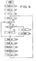
- a flag for abnormality is reset to zero signifying a malfunction of the throttle position sensor. That is to say, at the start of the program, it is assumed that the throttle position sensor is in an abnormal state regardless of the actual condition of the sensor.
- the opening degree ⁇ l is read out.
- the opening degree ⁇ l is stored as a degree ⁇ L at the last loop, although the last loop does not actually exist.
- the first loop starts and the current opening degree ⁇ l is read out again.
- it is decided whether the flag is set (1).
- the program proceeds to a step S6, where it is determined whether the difference between the current degree ⁇ l and the last degree ⁇ L is equal to or smaller than a predetermined small value ⁇ . Since the ⁇ l is equal to the ⁇ l at the first loop, the program proceeds to a step S8, where the ⁇ l is stored as the O L . At a step S9, the stored ⁇ l is rewritten to a fail-safe value ⁇ FAIL which represents 60 % of the value at the fully open throtde position, mentioned above as said first fail-safe signal.
- the drive pulley speed Np and the driven pulley speed Ns are read out at steps S10 and S11, and the actual transmission i is calculated at step S12.
- the desired transmission ratio id is obtained based on the driven pulley speed Ns and the fall-safe value ⁇ FAIL
- the duty ratio D is obtained at step S14 in accordance with the transmission ratios i and id. Namely, immediately after the engine start, the transmission ratio is decided by the fail-safe value ⁇ FAIL .
- step S7 When the accelerator pedal is depressed at a subsequent loop and the throttle position sensor operates normally, the difference
Landscapes
- Engineering & Computer Science (AREA)
- General Engineering & Computer Science (AREA)
- Mechanical Engineering (AREA)
- Control Of Transmission Device (AREA)
- Control Of Driving Devices And Active Controlling Of Vehicle (AREA)
Claims (2)
Applications Claiming Priority (2)
| Application Number | Priority Date | Filing Date | Title |
|---|---|---|---|
| JP286611/85 | 1985-12-19 | ||
| JP60286611A JPH0674017B2 (ja) | 1985-12-19 | 1985-12-19 | 無段変速機の制御装置 |
Publications (2)
| Publication Number | Publication Date |
|---|---|
| EP0228263A1 EP0228263A1 (fr) | 1987-07-08 |
| EP0228263B1 true EP0228263B1 (fr) | 1990-03-21 |
Family
ID=17706651
Family Applications (1)
| Application Number | Title | Priority Date | Filing Date |
|---|---|---|---|
| EP86309966A Expired - Lifetime EP0228263B1 (fr) | 1985-12-19 | 1986-12-19 | Système de commande pour transmission continue de vitesse |
Country Status (4)
| Country | Link |
|---|---|
| US (1) | US4823644A (fr) |
| EP (1) | EP0228263B1 (fr) |
| JP (1) | JPH0674017B2 (fr) |
| DE (1) | DE3669767D1 (fr) |
Families Citing this family (17)
| Publication number | Priority date | Publication date | Assignee | Title |
|---|---|---|---|---|
| JPH0676026B2 (ja) * | 1987-08-10 | 1994-09-28 | スズキ株式会社 | 連続可変変速機のクラッチ圧制御方法 |
| JPH0762625B2 (ja) * | 1988-02-09 | 1995-07-05 | 三菱重工業株式会社 | ノイズ消失検知方法およびその装置 |
| US5148722A (en) * | 1990-08-17 | 1992-09-22 | Chrysler Corporation | Method for invoking a shutdown on default |
| JPH05106728A (ja) * | 1991-10-11 | 1993-04-27 | Fuji Heavy Ind Ltd | 無段変速機の制御装置 |
| DE4313746C2 (de) * | 1993-04-27 | 2002-11-07 | Bosch Gmbh Robert | Verfahren und Vorrichtung zur Steuerung der Leistung einer Antriebseinheit eines Fahrzeugs |
| JP3538472B2 (ja) * | 1995-03-02 | 2004-06-14 | 本田技研工業株式会社 | 自動変速機の制御装置 |
| JP3478055B2 (ja) * | 1997-04-25 | 2003-12-10 | 三菱自動車工業株式会社 | 車両の制御装置 |
| DE19928554B4 (de) * | 1998-06-23 | 2007-03-29 | Nissan Motor Co., Ltd., Yokohama | Übersetzungsverhältnis-Regelvorrichtung und Verfahren zur Regelung des Überssetzungsverhältnisses bei einem stufenlos verstellbaren Toroidgetriebe |
| DE19952476A1 (de) * | 1999-10-29 | 2001-05-23 | Zahnradfabrik Friedrichshafen | Verfahren zur Steuerung eines CVT-Automatgetriebes |
| JP3788160B2 (ja) * | 2000-01-27 | 2006-06-21 | トヨタ自動車株式会社 | 車両用無段変速機の変速制御装置 |
| KR100416909B1 (ko) * | 2000-08-17 | 2004-02-05 | 안성순 | 목재 가공용 전동톱 |
| FR2834034B1 (fr) * | 2001-12-20 | 2005-04-22 | Renault | Procede de commande d'une transmission automatisee a rapports etages |
| JP3981317B2 (ja) * | 2002-10-04 | 2007-09-26 | ジヤトコ株式会社 | 車両用変速機の油圧異常低下判定装置 |
| JP3857240B2 (ja) * | 2003-01-29 | 2006-12-13 | 本田技研工業株式会社 | 無段変速機の故障判定装置 |
| DE102005044176A1 (de) * | 2005-09-16 | 2007-03-29 | Braun Gmbh | Haarentfernungsgerät |
| WO2010043192A2 (fr) * | 2008-10-16 | 2010-04-22 | Luk Lamellen Und Kupplungsbau Beteiligungs Kg | Système hydraulique de commande de transmission |
| US9337676B2 (en) * | 2014-01-07 | 2016-05-10 | Joseph Benigno | Outlet enclosure for device chargers |
Family Cites Families (10)
| Publication number | Priority date | Publication date | Assignee | Title |
|---|---|---|---|---|
| GB1569892A (en) * | 1976-01-31 | 1980-06-25 | Lucas Industries Ltd | Control circuits for vehicle transmissions |
| JPS5536611A (en) * | 1978-09-05 | 1980-03-14 | Nissan Motor Co Ltd | Throttle fail safe valve for automatic speed change gear |
| US4387608A (en) * | 1979-09-12 | 1983-06-14 | Robert Bosch Gmbh | Electronic control for a stepless vehicle transmission using a control member response to dynamic pressure |
| US4393732A (en) * | 1979-09-28 | 1983-07-19 | Nissan Motor Co., Ltd. | Abnormality treatment device for automatic transmission control device |
| JPS5977157A (ja) * | 1982-10-22 | 1984-05-02 | Nissan Motor Co Ltd | Vベルト式無段変速機の油圧制御装置 |
| JPH06100271B2 (ja) * | 1983-04-07 | 1994-12-12 | 日産自動車株式会社 | 無段変速機の制御装置 |
| JPH0730838B2 (ja) * | 1983-06-16 | 1995-04-10 | 日産自動車株式会社 | 無段変速機の制御装置 |
| JPS601449A (ja) * | 1983-06-16 | 1985-01-07 | Mitsubishi Electric Corp | 車輛用自動変速機の制御装置 |
| JPS6053257A (ja) * | 1983-08-31 | 1985-03-26 | Fuji Heavy Ind Ltd | 無段変速機の電子制御装置 |
| JPS6098254A (ja) * | 1983-10-31 | 1985-06-01 | Mazda Motor Corp | 電子制御式無段変速装置 |
-
1985
- 1985-12-19 JP JP60286611A patent/JPH0674017B2/ja not_active Expired - Lifetime
-
1986
- 1986-12-19 US US06/944,346 patent/US4823644A/en not_active Expired - Fee Related
- 1986-12-19 EP EP86309966A patent/EP0228263B1/fr not_active Expired - Lifetime
- 1986-12-19 DE DE8686309966T patent/DE3669767D1/de not_active Expired - Fee Related
Also Published As
| Publication number | Publication date |
|---|---|
| JPH0674017B2 (ja) | 1994-09-21 |
| US4823644A (en) | 1989-04-25 |
| DE3669767D1 (de) | 1990-04-26 |
| JPS62143742A (ja) | 1987-06-27 |
| EP0228263A1 (fr) | 1987-07-08 |
Similar Documents
| Publication | Publication Date | Title |
|---|---|---|
| US4764156A (en) | System for controlling transmission ratio of a continuously variable transmission for a motor vehicle | |
| EP0228263B1 (fr) | Système de commande pour transmission continue de vitesse | |
| EP0225747B1 (fr) | Dispositif de pilotage de la pression du liquide dans une transmission continue de vitesse | |
| US4782934A (en) | Control system for a continuously variable transmission | |
| US4803900A (en) | Transmission ratio control system for a continuously variable transmission | |
| EP0213852B1 (fr) | Commande de la pression d'huile d'une transmission variable d'une manière continue | |
| US4833944A (en) | Transmission ratio control system for a continuously variable transmission | |
| US4771658A (en) | System for controlling the pressure of oil in a system for a continuously variable transmission | |
| US4759236A (en) | System for controlling the pressure of oil in a system for a continuously variable transmission | |
| US4747325A (en) | Transmission ratio control system for a continuously variable transmission | |
| EP0234678B1 (fr) | Système de commande de rapport de transformation pour transmission à variation de vitesse infinie | |
| US4730522A (en) | System for controlling the pressure of oil in a system for a continuously variable transmission | |
| EP0240282B1 (fr) | Système de commande de la pression de l'huile pour un variateur continu de vitesse | |
| EP0233781B1 (fr) | Commande des rappos de changement de vitesse d'une transmission continue | |
| EP0260117B1 (fr) | Système de commande de rapport de transmission pour un variateur continu de vitesse | |
| US4942783A (en) | Transmission ration control system for a continuously variable transmission | |
| US4794819A (en) | Control system for a continuously variable transmission | |
| US4724724A (en) | System for controlling line pressure of a continuously variable transmission for a motor vehicle | |
| US4721019A (en) | Control system for an infinitely variable transmission | |
| EP0207228B1 (fr) | Système de commande pour une transmission continue | |
| US4760760A (en) | Control system for a continuously variable transmission | |
| US4827804A (en) | System for controlling the pressure of oil in a system for a continuously variable transmission | |
| EP0240285B1 (fr) | Système de commande pour un variateur continu de vitesse |
Legal Events
| Date | Code | Title | Description |
|---|---|---|---|
| PUAI | Public reference made under article 153(3) epc to a published international application that has entered the european phase |
Free format text: ORIGINAL CODE: 0009012 |
|
| 17P | Request for examination filed |
Effective date: 19870109 |
|
| AK | Designated contracting states |
Kind code of ref document: A1 Designated state(s): CH DE FR GB IT LI NL |
|
| 17Q | First examination report despatched |
Effective date: 19880919 |
|
| GRAA | (expected) grant |
Free format text: ORIGINAL CODE: 0009210 |
|
| AK | Designated contracting states |
Kind code of ref document: B1 Designated state(s): CH DE FR GB IT LI NL |
|
| ET | Fr: translation filed | ||
| REF | Corresponds to: |
Ref document number: 3669767 Country of ref document: DE Date of ref document: 19900426 |
|
| ITF | It: translation for a ep patent filed | ||
| PGFP | Annual fee paid to national office [announced via postgrant information from national office to epo] |
Ref country code: GB Payment date: 19901214 Year of fee payment: 5 |
|
| PGFP | Annual fee paid to national office [announced via postgrant information from national office to epo] |
Ref country code: FR Payment date: 19901228 Year of fee payment: 5 |
|
| ITTA | It: last paid annual fee | ||
| PLBE | No opposition filed within time limit |
Free format text: ORIGINAL CODE: 0009261 |
|
| STAA | Information on the status of an ep patent application or granted ep patent |
Free format text: STATUS: NO OPPOSITION FILED WITHIN TIME LIMIT |
|
| 26N | No opposition filed | ||
| PGFP | Annual fee paid to national office [announced via postgrant information from national office to epo] |
Ref country code: CH Payment date: 19911126 Year of fee payment: 6 |
|
| PG25 | Lapsed in a contracting state [announced via postgrant information from national office to epo] |
Ref country code: GB Effective date: 19911219 |
|
| PGFP | Annual fee paid to national office [announced via postgrant information from national office to epo] |
Ref country code: DE Payment date: 19911223 Year of fee payment: 6 |
|
| PGFP | Annual fee paid to national office [announced via postgrant information from national office to epo] |
Ref country code: NL Payment date: 19911231 Year of fee payment: 6 |
|
| GBPC | Gb: european patent ceased through non-payment of renewal fee | ||
| PG25 | Lapsed in a contracting state [announced via postgrant information from national office to epo] |
Ref country code: FR Effective date: 19920831 |
|
| REG | Reference to a national code |
Ref country code: FR Ref legal event code: ST |
|
| PG25 | Lapsed in a contracting state [announced via postgrant information from national office to epo] |
Ref country code: LI Effective date: 19921231 Ref country code: CH Effective date: 19921231 |
|
| PG25 | Lapsed in a contracting state [announced via postgrant information from national office to epo] |
Ref country code: NL Effective date: 19930701 |
|
| NLV4 | Nl: lapsed or anulled due to non-payment of the annual fee | ||
| REG | Reference to a national code |
Ref country code: CH Ref legal event code: PL |
|
| PG25 | Lapsed in a contracting state [announced via postgrant information from national office to epo] |
Ref country code: DE Effective date: 19930901 |
|
| PG25 | Lapsed in a contracting state [announced via postgrant information from national office to epo] |
Ref country code: IT Free format text: LAPSE BECAUSE OF NON-PAYMENT OF DUE FEES;WARNING: LAPSES OF ITALIAN PATENTS WITH EFFECTIVE DATE BEFORE 2007 MAY HAVE OCCURRED AT ANY TIME BEFORE 2007. THE CORRECT EFFECTIVE DATE MAY BE DIFFERENT FROM THE ONE RECORDED. Effective date: 20051219 |