EP0228204B1 - Architecture pour centraux de télécommunication à commande distribuée - Google Patents
Architecture pour centraux de télécommunication à commande distribuée Download PDFInfo
- Publication number
- EP0228204B1 EP0228204B1 EP86309524A EP86309524A EP0228204B1 EP 0228204 B1 EP0228204 B1 EP 0228204B1 EP 86309524 A EP86309524 A EP 86309524A EP 86309524 A EP86309524 A EP 86309524A EP 0228204 B1 EP0228204 B1 EP 0228204B1
- Authority
- EP
- European Patent Office
- Prior art keywords
- module
- data
- processor
- modules
- message
- Prior art date
- Legal status (The legal status is an assumption and is not a legal conclusion. Google has not performed a legal analysis and makes no representation as to the accuracy of the status listed.)
- Expired - Lifetime
Links
Images


Classifications
-
- H—ELECTRICITY
- H04—ELECTRIC COMMUNICATION TECHNIQUE
- H04Q—SELECTING
- H04Q11/00—Selecting arrangements for multiplex systems
- H04Q11/04—Selecting arrangements for multiplex systems for time-division multiplexing
-
- H—ELECTRICITY
- H04—ELECTRIC COMMUNICATION TECHNIQUE
- H04Q—SELECTING
- H04Q11/00—Selecting arrangements for multiplex systems
- H04Q11/04—Selecting arrangements for multiplex systems for time-division multiplexing
- H04Q11/0407—Selecting arrangements for multiplex systems for time-division multiplexing using a stored programme control
-
- H—ELECTRICITY
- H04—ELECTRIC COMMUNICATION TECHNIQUE
- H04Q—SELECTING
- H04Q2213/00—Indexing scheme relating to selecting arrangements in general and for multiplex systems
- H04Q2213/13107—Control equipment for a part of the connection, distributed control, co-processing
-
- H—ELECTRICITY
- H04—ELECTRIC COMMUNICATION TECHNIQUE
- H04Q—SELECTING
- H04Q2213/00—Indexing scheme relating to selecting arrangements in general and for multiplex systems
- H04Q2213/13141—Hunting for free outlet, circuit or channel
-
- H—ELECTRICITY
- H04—ELECTRIC COMMUNICATION TECHNIQUE
- H04Q—SELECTING
- H04Q2213/00—Indexing scheme relating to selecting arrangements in general and for multiplex systems
- H04Q2213/13176—Common channel signaling, CCS7
-
- H—ELECTRICITY
- H04—ELECTRIC COMMUNICATION TECHNIQUE
- H04Q—SELECTING
- H04Q2213/00—Indexing scheme relating to selecting arrangements in general and for multiplex systems
- H04Q2213/13299—Bus
Definitions
- This invention relates to stored program controlled switching systems, and, more specifically, to apparatus and methods for distributed control telecommunication switching systems.
- Modern telephone switching systems have achieved flexibility through the use of program control wherein a processor system, under the control of a program stored in memory, controls the operations of the system.
- many modern systems use the technique of distributed control in which the system is broken down into a number of modules and each module is controlled by its own processor.
- the 5ESS TM switch described in U. S. Patent 4,322,843 each module processes all signals, associated with source and destination ports connected to customers or to trunks to other switches, of that module and handles all intramodule switching between ports connected to that module.
- this system also uses a central processor for handling a large class of call processing functions associated with intermodule calls or requiring the use of a data base, such as the relationship between directory numbers and ports, that is used by all modules.
- the processors of the various modules communicate with each other via data messages transmitted over the switching network of the system to a message switch which then retransmits each message to the module for which that message was destined.
- a message switch which then retransmits each message to the module for which that message was destined.
- Such an arrangement introduces considerable delay in the transmission of each message.
- the total delay which can be allowed in processing and responding to incoming signals, such as a customer answer is limited in commercial telephone systems by telephone requirements according to international standards. Therefore, the number of such data messages which may be exchanged among modules in order to respond to customer requests is limited. This limitation helps to determine the assignment of functions to module processors and the central processor.
- central processor is used for performing many of the basic data processing functions required to set up each telephone call, it is necessary that a highly reliable central processor he available in each switch. Further, these substantial data processing requirements lead to the requirement of a processor having very high processing capability in order to handle a very large office. It is an objective of distributed control telephone switching systems to be able to grow readily, by the addition of individual switching modules, one module for each growth step, from a small size of one switching module serving perhaps 5,000 customers to sizes having many modules and serving in excess of 100,000 customers.
- Modular Electronic Switching System for Small and Medium Size Offices discloses a switching system that includes a plurality of switching modules each with its own module processor for controlling connection operations of a network, an intermodule switch, and an administrative control and maintenance processor. Calls are set up under the control of the switching module processors and the administrative control processor which provides much of the translation information necessary for such call set up.
- an illustrative distributed control switching system comprising a plurality of switching modules that advantageously use a high-speed common data communication means to rapidly exchange call control messages such that call processing functions previously performed by a central processor are advantageously distributed to individual switching module processors.
- a high-speed common data communication means offers low interprocessor message latency permitting many more messages to be exchanged among module processors in order to set up a call than in a common prior art system.
- the presence of a high-speed common data communication means permits a module processor to query a data base stored in another module processor instead of requiring that data necessary for performing most data processing tasks be immediately accessible within a module processor.
- Such an arrangement also permits data to be broadcast to all switching modules of the system for rapidly transmitting the large amount of data required. These factors permit the migration of central processor call processing functions to the switching module processors. By focusing in the switching module processor all strategic control operations, a less expensive lower-capacity, lower-reliability central processor may be used. This substantially decreases the cost of a small office serving, for example, 5,000 lines with one switching module while still permitting such an office to grow to a very large size.
- An exemplary parallel distributed control telecommunication switching system illustrating this invention has a plurality of switching modules and connection means for selectively setting up connections among ports and intermodule outlets of the switching modules.
- the system also includes a processor for controlling the connection means, and intermodule connection means for interconnecting intermodule outlets of different ones of the modules.
- the system further includes an administrative processor for communicating with a man-machine interface and a common data communication means for transmitting data packets among the module processors.
- the module processors communicate with each other via such data packets to cooperatively set up connections between ports on different modules substantially without the use of the administrative processor.
- a time multiplex switch is used as the means for selectively interconnecting the outlets of the different modules; in another specific embodiment, these outlets may be directly connected in groups between the modules.
- the processor of the module containing the source port of a call sends data on intermodule outlet availability to the processor of the module containing the destination port of that call so that the two processors can cooperatively control the set-up of an intermodule path.
- a call between ports on different modules is set up as follows: a seizure of an incoming port by a line or an incoming trunk is detected and the directory number of the terminating party is collected. This process may be performed by monitoring the incoming port and connecting the incoming port to a receiver or it may be performed by receiving data messages from another switch over a common channel signaling facility. The destination directory number is then translated to find the identity of the destination port or the destination multiport group. In the latter case, an additional step is required to find an available port in the multiport group. Next, a message comprising one or more data packets is sent to the module processor of the destination port requesting that a connection be set up to that port.
- a message is sent from the module containing the destination port to the module containing the source port to complete the connection by setting up a connection between an appropriate outlet and the source port.
- the interprocessor data message identify available outlets of each of the modules and the modules cooperate to select an available outlet of each module for use in setting up the connection. If a time multiplex switching network is used for intermodule connections, an additional message including the identification of an available outlet is sent to that switching network to set up the required intermodule connection.
- no operations are required of the administrative processor so that all the call processing operations for this call are performed by the module processors.
- the administrative processor broadcasts data, such as initialization data, for example, or common program text, to all module processors requiring such data.
- data such as initialization data, for example, or common program text
- a local area network which transmits data at a rate of ten megabits/second and uses carrier sense multiple access/collision detection, is used to interconnect the module processors.
- the use of such a network implies a transmission time that, even for a relatively long 100 byte message, is less than 0.1 milliseconds; in contrast, a similar message sent over a 64 kilobit/second channel through a time division network, would encounter a transmission delay in excess of twelve milliseconds.
- trunks interconnecting a given pair of switches are grouped; when a trunk for a switch to a specific destination is required, an available member of the appropriate group is hunted.
- lines to a private branch exchange (PBX), for example, of a business are grouped into multiline hunt groups. More generally, multiport hunts must be executed to find an available port connected to a member of the line group or trunk group.
- PBX private branch exchange
- port hunting is performed by the central processor.
- each port group has an associated data base which retains the current state of activity of each port in the group; this associated data base is maintained by a hunting module for that group.
- Any calls originating in other modules that require the use of a port in the group require that a message be sent to the hunting module to select an available port.
- a highly reliable central processor complex for performing port hunting a call processing step that must be executed for any outgoing call, tandem call, or call to a multiline group.
- FIG. 1 shows a prior art distributed processing telecommunication switching system similar to that described in more detail in the previously cited Beuscher patent.
- the system includes switching modules 1A, 2A, 3A,...,4A each of which includes ports for connection to lines and trunks, and intermodule outlets for setting up intermodule paths.
- ports 101A,...,102A;...;111A,...,112A and intermodule outlets 121A,...,122A are shown for switching module 1A. While individual ports and outlets are shown, some of the ports, connected to pulse code modulation (PCM) facilities, and all of the outlets are grouped on time multiplex facilities where one facility can carry many simultaneous voice or data channels. This applies also to the systems shown in FIGS. 2 and 3.
- PCM pulse code modulation
- the intermodule outlets of each of the switching modules 121A,...,122A;221A,...,222A;. 321A,...,322A;...;421A,...,422A are connected via paths 1210A,...,1220A;2210A,...,2220A; 3210A,...,3220A;...;4210A,...,4220A to time multiplex switch 6A.
- the time multiplex switch can set up connections between any pair of these outlets from different switching modules.
- An intermodule connection between two ports connected to different modules is formed by a connection in time multiplex switch 6A between two intermodule outlets and intramodule connections between each of these two intermodule outlets and one of the two ports.
- Message switch 8A Also connected to the time multiplex switch via data channels 821A,...,822A is a message switch 8A.
- Message switch 8A also receives data from a central processor and administrative module 7A over data channel 720A, and from the processor 630A of time multiplex switch 6A over data channel 636A.
- the message switch 8A can set up data connections between any of its inputs and any of its outputs.
- the central processor and administrative module 7A includes a processor 730A comprising a central processing unit (CPU) 731A, memory 732A, data interface 733A for communicating with message switch 8A, and a disk interface 734A for communicating with a disk 735A.
- the processor communicates with a man-machine interface 736A for communicating via data path 741A with control console 740A.
- Each switching module has its own processor.
- Processor 130A for switching module 1A comprises a central processing unit 131A, memory 132A and an interface 136A for communication via data path 137A with one of the intermodule outlets of switching module 1A such as outlet 122A. Those outlets which are used for communicating with the processor are also switched through time multiplex switch 6A to message switch 8A.
- the processors of the different switching modules communicate with each other and with the central processor and administrative module via data channels connected to time multiplex switch 6A and thence via data channels 821A,...,822A to message switch 8A.
- the data rate for these data messages sent as data packets is the same as the data rate for inter-customer communication. For this system, this data rate is the standard 64 kilobit/second rate characteristic of the commonly available pulse code modulation (PCM) voice communication systems.
- PCM pulse code modulation
- a 100 byte data packet incurs a delay of over 12 milliseconds to reach the message switch and if the message is destined for another switch module incurs another 12 millisecond delay to reach that second module.
- the delay is significantly longer because additional delays are encountered in the message switch itself and because the processors are usually not ready immediately to process a received message.
- the delay in sending a message between two modules and responding in the destination module to that message is 60 milliseconds minimum and the delay in sending a message between a module and the central processor and responding to that message is 30 milliseconds minimum.
- the number of messages which can be exchanged between modules and between modules and the central processor and administrative module is limited by these long delays.
- the allocation of processing tasks among the switching module processors 130A, 230A, 330A,...,430A and a central processor 730A is to a considerable extent determined by the timing restrictions associated with exchanges of messages among the modules and between the modules and the central processing module.
- International standards have set a requirement that the cross-office delay across a telecommunication switch is limited to 180 milliseconds average. This requirement states that from the time a switch receives a request for a connection until that connection is set up, no more than 180 milliseconds average may elapse. With this timing requirement, and allowing for data processing actions in response to received data messages it is apparent that the software structure of the prior art system of FIG.
- the dynamic intermodule data base includes three elements which are required for the set up and disconnection of the bulk of telephone calls. These are the routing, trunk assignment, and path assignment data bases.
- the routing data base is that data base which is used to select a particular outgoing interoffice trunk group for an outgoing or tandem call, the trunk data base is used for selecting an idle trunk in a group and for maintaining a list of idle trunks, and the path assignment data base is used for selecting a path to interconnect two modules.
- the central processor executes the routing, trunk assignment and path selection processes. Such an arrangement advantageously minimizes the number of messages which must be exchanged among different processors.
- FIG. 2 shows an exemplary embodiment of a system adapted for operation in accordance with the principles of the present invention.
- the interface such as interface 136A (FIG. 1), to data channels for communicating over the outlets of each switching module for communicating messages between module processors has been replaced by a communicative medium (CM) interface such as CM interface 133 (FIG. 2) for accessing a common data communication medium 90.
- CM communicative medium
- This common data communication medium being separate from the customer communication system, can be operated at a different rate, in the exemplary embodiment, at 10 megabits per second.
- the data communication system includes the communication medium and the CM interfaces.
- the high data rate communication medium allows many messages to be transmitted within a short period.
- a data ring which maintains the ordering of packets, could also be used as a common communication medium, even though different packets are being transmitted concurrently in different segments of the ring.
- Substantially all functions necessary for setting up intermodule connections are carried out by the module processors working in cooperation with each other and exchanging data over the communication medium, without the need for data processing operations carried out by the administrative processor 730. (An exception would be the generation of data for a test connection requested by the administrative processor.)
- the high data rate common communication medium makes it possible to exchange many more data messages between processors in order to set up a connection, thus removing a constraint which, in the prior art system of FIG. 1, required that many data processing functions be carried out by a central processor.
- Data messages are used, for example, to transmit data to allow a cooperative process for selecting available outlets for use in a path between two switching modules or to access data in the memory of another processor.
- FIG. 2 shows four typical switching modules, 1,2,3,...,4 representing four of the switching modules of a typical switch. Also shown are a time multiplex switch 6 and an administrative module 7. Switching modules 1,2,3,...,4, time multiplex switch 6 and administrative module 7 are all connected to common data communication medium 90. Each of the switching modules are switching modules of the type described in the previously cited Beuscher et al. patent. Switching module 1 is connected to ports 101,...,102;...;111,...,112; each group of ports is connected to a group of lines or interoffice trunks. (Such a group of trunks is not a trunk group as the term is commonly used and used herein.) Switching module 1 also is connected to a group of intermodule outlets 121,...,122.
- Switching module 1 is controlled by switching module processor 130 comprising CPU 131, memory 132, and communication medium (CM) interface 133 for interfacing with communication medium 90.
- Switching modules 2,3,...,4 have corresponding processors 230,330,...,430, respectively, groups of ports (201,...,202;...;211,...,212), (301,...,302;...;311,...,312),..., (401,...,402;...;411,...,412), respectively, connected to lines and trunks, and groups of intermodule outlets (221,...,222), (321,...,322),..., (421,...,422), respectively.
- the illustrative embodiment of FIG. 2 includes a time multiplex switch 6 which is connected to the intermodule outlets of all the switching modules. This time multiplex switch makes connections among such intermodule switching facilities in order to set up a path between ports on two different switching modules.
- Time multiplex switch 6 also includes a processor 630 for setting up and tearing down connections in the switch.
- the intermodule outlets from switching modules 1,2,3,...,4 are connected to the time multiplex switch by paths (1210,...,1220),(2210,...,2220), (3210,...,3220),...,(4210,...,4220), respectively.
- the illustrative embodiment of FIG. 2 also includes an administrative module 7 comprising a processor 730 and a bulk storage disk 735.
- the processor has a central processing unit 731, local memory 732, CM interface 733 for communicating with communication medium 90, and disk interface 734 for communicating with the disk 735.
- the processor communicates with man-machine interface 736 for communicating via data path 741 with a control console 740.
- the disk is used for storing initialization data such as the program text required in processors 130, 230, 330,...,430 and 630, to control switching modules 1,2,3,...,4 and time multiplex switch module 6, respectively.
- the control console is used for displaying maintenance and administrative data to and for accepting input data and control messages from an operations or traffic control craftsperson or supervisor.
- a duplicate communication medium 91 is provided, and each processor is provided with access to both of the communication media 90 and 91.
- CM interface 133 of processor 130 of module 1 has access to communication medium 90 via data path 134 and has access to duplicate communication medium 91 via data path 135.
- Such an arrangement permits the system to survive the failure of either communication medium or a failure which causes one of the communication medium interfaces to place a short circuit across one of the media.
- a telephone subscriber such as telephone station 116 connected by path 114 to port 101, or an incoming trunk such as 115 connected by path 117 to port 111, both ports on switching module 1, sends an origination signal by lifting the handset from the cradle or, in the case of an incoming trunk, a seizure signal by applying, removing, or reversing a voltage to the port.
- the switching module processor such as processor 130
- the directory or destination number of the destination telephone subscriber is received via the port and accumulated in the processor 130.
- seizure and number signals are sent over a separate data channel and may be received in a different module; that module sends a message comprising the received data to the module containing the trunk port.
- the number is translated to find the identity of a destination port for communicating with the destination customer.
- the translation may be carried out in the module processor, or a preliminary translation may be made in that processor to select an appropriate translating processor which will make the translation. If the call can be set up within the module no further communication with other modules is required. If the call is routed via a port of another module, data messages are sent via data communication medium 90 to the other modules involved and the call is set up cooperatively between the incoming or originating (source) module and the outgoing or terminating (destination) module. A message is also sent to the time multiplex switch to set up the connection between outlets of the source and the destination modules. In accordance with the teachings of the present invention, the intervention of the administrative module 7 is not required. This is made possible by retaining an appropriate up-to-date data base in each module and by sending call control messages between the modules. As illustrated further in FIGS. 8-11, a plurality of data messages among the switching modules transmit all data needed to complete the calls.
- FIG. 3 The alternative illustrative embodiment of FIG. 3 is similar to that of FIG. 2 except that no time multiplex switch is required. Instead the switching modules are directly interconnected via their intermodule outlets. While this arrangement is meant primarily for use in smaller offices, it can also be used in larger offices with the occasional use of one switching module to make a tandem connection between two other switching modules. If switching modules are to be fully interconnected without an intermediate switch such as time multiplex switch 6, the size of the intermodule outlet group interconnecting any two modules in a large system may not be large enough to act as an efficient outlet group; some additional overflow arrangement such as intermodule tandem switching is required.
- Each switching module of the system of FIG. 3 has the same outlets as in the system of FIG. 2.
- Modules 1,2,3,...,4, have outlets (121,...,122),(221,...,222),(321,...,322),...,(421,...,422), respectively.
- the paths connected to intermodule outlets are connected to other outlets, not to a time multiplex switch.
- the paths between intermodule outlets are numbered such that the first digit represents the number of one of the modules connected by an outlet, the second digit represents the other module.
- the rule is used that the first digit of the number of a path is always equal to or less than the second digit.
- FIG. 3 shows modules 1,2,3,...,4, with paths and dashed lines [1100,...,1101;1200,...,1201;1300,...,1301;...;1400,...,1401], [1200,...,1201;2200,...,2201;2300,...,2301;...;2400,...,2401], [1300,...,1301;2300,...,2301;3300,...,3301;...;3400,...,3401],..., [1400,...,1401;2400,...,2401;3400,...,3401;...;4400,...,4401], respectively.
- module 2 has paths 1200,...,1201 connected to module 1; dashed lines 2200,...,2201 representing the unneeded intramodule paths of module 2; paths 2300,...,2301 connected to module 3;...; and paths 2400,...,2401 connected to module 4.
- each module processor executes a program called an operating system.
- Operating systems are well known in the art.
- One such system is the Duplex Multi-Environment Real Time (DMERT) operating system, described in Grzelakowski et al.: "DMERT Operating System", Bell System Technical Journal , Vol. 62, No. 1, Part 2, January 1983, pp. 303-322.
- DMERT Duplex Multi-Environment Real Time
- Among the functions executed under the control of an operating system are those of transmitting messages, receiving messages, and associating received messages with a process block for controlling a process such as a telephone call.
- a process resident in one processor reaches a stage where it must communicate with another processor, it does so by generating a message comprising one or more data packets to that other processor.
- Each packet includes its own process identification and, if known, the identification of the process executing in the other processor with which communication is desired.
- the interplay of processes and messages is illustrated further in FIGS. 8-11.
- the choice comprises a routing stage for selecting a trunk group and a trunk hunting stage for selecting a trunk within that group. All member trunks of a trunk group have a common destination, so that a process for routing telephone or data traffic need only be concerned with the choice of trunk groups.
- a routing process normally finds a preferred choice trunk group and provides an alternate route trunk group in case all trunks in the preferred group are busy.
- a well-designed routing process needs to provide the flexible type of first choice and alternate routing available in present day telecommunication switches such as the 4ESS TM switch manufactured by AT&T Technologies, Inc. In such switches, different first choice and alternate routes may be selected according to the traffic conditions existing at a particular time.
- the alternate routing can be further modified by input from the traffic supervisor so that the system may respond properly to emergency conditions (such as the outage of a large number of trunks or the existence of an emergency which causes a large amount of traffic to be generated from and to one destination) or for special traffic conditions such as those which exist on Mother's Day.
- emergency conditions such as the outage of a large number of trunks or the existence of an emergency which causes a large amount of traffic to be generated from and to one destination
- special traffic conditions such as those which exist on Mother's Day.
- the routing control for any given destination be under the control of a single data base. Because of the highly dynamic nature of the traffic it is further desirable that, as a minimum, the control for routing for all related traffic be maintained by a single processor.
- a trunk within that trunk group can be selected by a separate trunk hunting process.
- the choice of an available trunk must be made in such a way that the trunk is not simultaneously seized by two switching modules processing different calls. This suggests the use of a single data base for each trunk group, or as discussed with respect to FIG. 11, the use of a data base replicated in and constantly updated for each module.
- this stage of switching is a non-blocking time multiplex space division switch, then it is necessary that the two modules being interconnected both have the same time slot available for a given call; it is also necessary to ensure that the same time slot is not simultaneously seized by the two modules for different calls.
- the processor that makes a decision as to which path is to be used must have knowledge of at least a subset of the available time slots of each of the modules involved in the connection.
- FIG. 4 is an illustrative memory layout of a process block 800 which contains information necessary to control the actions of one switching module for one call.
- the process block 800 includes a process identification number 801 which is used to identify the call and which is used to link any incoming messages to that process block.
- Process block 800 also contains the identifications 802,803 of processes that are linked to this process either within the module or in outside modules.
- the process block 800 further contains the identifications of the source and destination ports 804,806 used in a call and the path data 805 for the connection set up either within a module or between modules to connect such ports.
- the process block 800 also includes the directory number 807 of the terminating customer.
- FIGS. 5-7 show further illustrative memory layouts for controlling telephone calls.
- FIG. 5 is a layout of memory used for routing.
- Each destination subscriber directory number or destination number includes an area code or office code, referred to herein, for convenience, as a destination code.
- Each destination code has an associated route index, one of the n+1 route indexes 811,...,812 of table 810. Many destination codes may share a route index; for example, this is likely to be the case if the destination codes sharing a route index are all for subscribers connected to the same switch.
- Each route index is associated with one of the m+1 entries in table 825; each such entry comprises a primary trunk group, 826,...,828, and an alternate route index 827,...829.
- a route index may also indicate an intraswitch destination by a special value, representing an intraoffice destination code, for the "primary trunk group.”
- a route index When a route index has been found a search is first made for an available trunk in the primary trunk group. If no idle trunk is available in the primary trunk group, then the alternate route index is used to obtain a new primary choice trunk group and a new alternate route index. The final alternate route index will be that of an overflow tone or of an announcement indicating that no facilities are available for communicating with the destination switch.
- Such routing is well known in the prior art and is described, for example in W. Ulrich et al.: "Translations in the No. 1 Electronic Switching System", Bell System Technical Journal , v. 43, no. 5, part 2, September 1964, pp.
- FIG. 6 is a layout of a memory block 830 used for selecting an idle trunk in a trunk group.
- the first two slots of this memory contain a pointer to the first idle trunk 831 (i.e., the trunk which has been idle the longest) and the last idle trunk 832 (i.e., the trunk which was most recently used).
- there is one entry per trunk such as 833,834,835,836, and 837, which either comprises data concerning the current use of the trunk or comprises a pointer to the next most idle trunk.
- Entries such as 833 and 835 for busy trunks comprise path data for that trunk.
- the idle trunks, represented by memory entries 834,836,837 are linked together in a list each pointing to the next most idle trunk.
- the last idle trunk entry 837 has no pointer but a special indication to indicate that there are no further idle trunks.
- the first idle trunk is seized; then, the identity of the next idle trunk, found in the information slot associated with the trunk being seized, replaces the information in the first idle trunk slot of the trunk group information.
- the trunk marked "last idle trunk” is seized, a special indication is placed in the first idle trunk pointer indicating that no trunks are available.
- the contents of the last idle trunk pointer are used to find the previous last idle trunk and that trunk is then linked to the trunk which was just released.
- the trunk which was just released is marked "last idle trunk", indicating that there are no further idle trunks, and its identity is placed in the last idle trunk slot. Line hunts can be performed in the same way as trunk hunts.
- FIG. 7 shows a layout 840 of memory used to find available paths between a switching module and other switching modules.
- intermodule outlets are grouped, in groups 841,...,842 each group containing outlets to one other switch module.
- group 841 may represent channels between modules 1 and 2. If a time multiplex switch is used, any outlets may be used for connection to any other module, so that a group need not be tied to a particular module.
- a busy-idle indication 0 or 1 is maintained in a bit position such as 843, to represent the state of a corresponding channel.
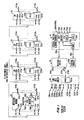
- FIGS. 8-11 are a combination of flow diagram and message exchange diagrams illustrating the processing of an incoming telephone call. Processing steps are shown in columns under the caption of the module processor performing the processing steps. Processors are identified according to their use in the illustrative telephone call. Messages are shown as heavy lines interconnecting boxes in columns of the processor sending the message and the processor receiving the message. The content of the message, where not obvious, is shown in a parallelogram associated with the heavy line.
- An originating call is one which originates from a subscriber connected to this switch.
- An incoming telephone call is a call originated by a subscriber connected to another switch, which has been connected by an incoming trunk to this switch.
- the actions for incoming and originating calls are very similar; the primary differences are that for an originating call the signals are sent to and received from an originating subscriber whereas for an incoming call, the signals are sent to and received from another switch.
- An incoming call from an incoming trunk 115 connected port 111 on switching module 1 to a customer telephone station 315 connected by line 314 to port 301 on switching module 3 will be illustrated first.
- a tandem call from trunk 115 that is routed to outgoing trunk 415 connected by path 414 to port 401 on switching node 4 will also be illustrated.
- the incoming call is received in the incoming switching module (action box 501).
- a process block 800 is set up for processing the call by the operating system of processor 130.
- a similar process block is subsequently set up in a destination module when the appropriate message 509 or 561 is received.
- the incoming switching module controller, switching module processor 130 of switching module 1 in the exemplary call tests whether the call terminates in this switch or in another switch (test 503). This test is based on the destination code. If it is determined that this call terminates in this switch then a translation is made to determine the terminating module (action box 505). In the illustrative terminating call, this is assumed to be module 3.
- a message 509 is sent to that terminating module processor by action box 507.
- the text of the message 509 includes the destination number, the incoming call process number assigned to the call by the incoming switching module 1, a summary of path availability between the incoming and terminating switching modules obtained from memory block 840 of processor 130, and the type of message being sent.
- This message is received by the terminating switching module processor 330 which then translates the destination number which was received in the message to find the corresponding terminating port number 301.
- the terminating switching module processor 330 tests the terminating port to see if it is idle (test 513).
- message 515 including a call type (in this case busy) and the incoming process number is sent back to originating switching module processor which (action box 517) connects busy to the incoming trunk attached to port 111 to inform the originating customer that the terminating customer is busy.
- terminating switching module processor 330 selects a path, from among those listed as being available in the received message, that is available in the terminating switching module, and sets up a ringing connection to the terminating customer and a tone connection to the path leading to the incoming customer (action box 521).
- the path is selected using memory block 840 of processor 330, and the received path availability data.
- the terminating switching module processor 330 then sends message 523 over the communication medium 90 to the incoming switching module processor 130.
- Message 523 includes an identification that includes the incoming process number, a message type indicating that a ringing connection has been set up, and the path number chosen for the eventual talking connection and the connection to send audible tone back to the originating customer.
- the incoming switching module processor 130 in response to reception of this message sets up a connection from port 101 of the incoming trunk to the intermodule outlet identified by the path number received in the message (action box 525).
- the terminating switching module processor 330 also sends message 531, including the identifications of the originating and terminating switching modules and the selected path to the time multiplex switch module processor 630.
- the time multiplex switch module 6 under the control of processor 630 sets up a connection between the selected outlets to the incoming switching module 1 and the terminating switching module 3.
- the terminating switching module 3 under the control of processor 330 sets up the talking connection and sends message 545 to the incoming switching module processor 130 (action box 543).
- Message 545 includes the incoming process number and the type of call action requested, in this case, to transmit an answer signal to the switch at the other end of the incoming trunk connected to port 111.
- the incoming switching module processor 130 changes its call record to indicate that the call is in the talking state (action box 547), and sends the answer signal over the incoming trunk.
- test 503 (FIG. 8) for checking whether the terminating call was destined for the customer connected to this switch or to another switch. If the result of test 503 indicates that this call does not terminate on this switch, then the call is a tandem call in which this switch is neither the originating nor the terminating but an intermediate switch.
- the incoming switching module transmits a tandem message 553 to a routing switching module (action box 551).
- module 2 is the routing switching module, and processor 230 executes the routing process.
- the message 553 contains a destination directory number representing the number dialed by the originating telephone subscriber and an incoming process number to identify the call.
- the message also contains the call type indicating that this is a tandem call.
- routing switching module processor 230 determines an appropriate trunk group to be used for this call (action box 555). Processor 230 then sends a trunk hunt message 557 to a trunk hut switching module, assumed in this example to be switching module 3. The trunk selection message again comprises the incoming process number to identify the call, the destination number, and a trunk group.
- trunk hunt switching module processor 330 selects an idle outgoing trunk (action box 559) and sends to the switching module containing this trunk a tandem completion message 561 which includes a trunk number, type of call, and the incoming process to identify the call. Assume that the selected trunk is outgoing trunk 415 connected to port 401 of module 4.
- terminating switching module processor 430 controls the sending of the destination number over the selected outgoing trunk 415 connected to port 401 and generates a path availability message 565 to incoming switching module 1 (action box 563). Again, this path availability message includes the incoming process number as an identification.
- incoming switching module processor 130 selects a path and sets up an internal connection in switching module 1 between the incoming trunk 117 connected to at port 111 and the intermodule outlet of the selected path.
- Incoming switching module processor 130 then sends a message 569 including the selected path number and the incoming process number as identification to the terminating switching module 4 so that the terminating switching module can set up its internal connection between its intermodule outlet and port 401 connected to outgoing trunk 415 (action box 571).
- the incoming switching module processor 130 also sends a message 573 to the time multiplex switch module processor 630 containing an identification of the path and the originating and terminating switching modules.
- the time multiplex switch module processor 630 controls the setting up of a connection in time multiplex switch 6 between the selected links to the incoming module 1 and terminating module 4 (action box 575).
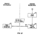
- the broadcast facilities of the common data communication medium can select trunks by an alternate method. This is illustrated in FIG. 11 which is entered at the time that a decision has been made that an outgoing trunk is necessary.
- the routing is performed in each switching module. This is reasonable since as discussed below, all switching modules have a complete record of availability of trunks.
- the incoming switching module first selects a first choice trunk group (action box 951); it does so by selecting a preferred route through the selection of a route index, based on the destination code, as discussed earlier.
- the route index also give an alternate route index which allows the alternate routing procedure described below to be invoked.
- Each switching module has complete data on availability of all trunks.
- the incoming switch module then makes a test 953 to see if there are any idle trunks in the group being tested. If not, then the next choice trunk group is selected (action box 955) by identifying the trunk group specified by reading the contents of routing memory indicated the alternate route index; the routing memory contents will also provide an additional alternate route index in case this test should also fail. Following the selection of the next choice trunk group, a test is again made (test 953) to see if any idle trunks are available in the group. Eventually, a group will be tested which does have idle trunks. (Not shown is the case in which no trunks are available; in that case, the last alternate route index is an indication that the customer should have overflow tone returned from the incoming or originating switching module to that customer.)
- a candidate trunk is selected but not marked busy (action box 957).
- a message is then broadcast to all switching modules indicating the selection of this candidate (action box 959).
- other modules including the terminating switching module connected to the candidate trunk, mark the selected trunk busy (action box 963).
- the sending module in this case the incoming switch module 1, also receives this broadcast message (action box 961) and makes a test 965 to see if the selected trunk is still not marked busy in its own records.
- action box 957 is reentered to select another candidate trunk.
- the selected trunk is still not marked busy; in action box 967 it is then marked busy.
- a message 968 is then sent to the terminating switching module specifying the trunk number, the call type, the incoming process number, and path availability.
- terminating switching module in action box 969 sends the destination number over that trunk and returns to the incoming switch module a message similar to message 565 of FIG. 9. The rest of the call processing is the same as shown in FIG. 9, entered in action box 567.
- a trunk release broadcast message is sent (action box 983) to all switching modules.
- each module such as the terminating switching module, receiving the broadcast message marks the trunk idle (action box 987) and the module which sent the broadcast message, such as the incoming switching module, also marks the trunk idle when it receives its own broadcast message (action box 985).
- This trunk hunting procedure can be similarly used for hunting for an idle port in any multiport group.
- this alternative mode of selecting trunks is only one way of using a common medium or other broadcast means to pass data among the modules so that each module can hunt for an idle port in a multiport group. For example, if a token method is used to access the common medium, including a ring, and if the module performing the hunt does so only when the token is in its possession, and if response to broadcast messages for making a port busy is given interrupt level priority over port hunting, and if a port make busy broadcast message is sent out before the token is released, then a module performing the hunt can have confidence that a port marked available has not been hunted for and selected by another module; in that case, a candidate port is, in fact, a port that can be selected since the message announcing any previously selection of a candidate port would have arrived and have been acted upon before the hunt was initiated. Any arrangement will suffice which ensures that a candidate port is still available at the time a commitment is made to select that port. Similarly, any broadcasting arrangement that will accomplish the goal of notifying other processors rapidly
- This method of notifying modules of the availability and unavailability of trunks in a group may be more generally applied to the notification of processors in a distributed processing system of the availability and unavailability of resources such as a printer. Further, it is not restricted to use on resources which are grouped but can, as in the case of a single printer, be used for single resources.
- the use of this approach permits each processor in a distributed processing system to make its own decision as to whether a resource is available. The resource is available, the processor seizes that resource; otherwise, the processor defers such seizure until the resource or resources becomes available, or otherwise disposes of the request for that resource.
- the need for centralized allocation of the resource either by the controller of the resource or by a centralized controller or processor is thereby eliminated.
- Multicasting is another alternative, under which a selected subset of processors receive a message with a given destination identification.
- Each communication medium interface is equipped to recognize and accept messages identified by one of a group of arbitrary destination addresses; each of the communication medium interfaces which are to receive a group of messages are set up to be responsive to the destination addresses for that group.
- One such group is the group of module processors, and messages for module processors (but not the administrative module processor or the processor of the time multiplex switch module) are identified with a unique destination address; this address can then be used for multicasting port availability data messages.
- Another advantage of having a common medium 90 available for the transmission of data messages among the switching modules is that the initialization of these switching modules can be carried out rapidly because of the high data transmission rate of the common medium.
- Initialization of a switching module is required whenever the memory of one or more switching module processors has been mutilated because of a hardware or software error or whenever the system is turned on initially. Sometimes, initialization is also required when program changes are introduced into the system. Whenever such initialization is required the source of the initialization is the administrative module which has access to the bulk storage disk 735.
- the initialization data usually comprise a substantial body of data that is common to all switching modules (such as program text) and some initialization data which is peculiar to each switching module.
- the initialization data that is common is broadcast or multicast by the administrative module (action box 1002, FIG. 12).
- Each of the switching modules which receive this broadcast makes a test 1004 of whether initialization is required for this module. If not, the broadcast message is ignored. If so, the common data for this switching module is initialized (action box 1006). Subsequently, the administrative module transmits module specific data to each module in turn.
- Action box 1008 indicates that the administrative module transmits module specific data for a specific module.
- the switching module Upon receipt of this data from the communication medium, the switching module initializes module specific data (action box 1010) and after initialization has been completed, sends an initialization complete message (action box 1012) back to the administrative module. In response, the administrative module changes its own data base to reflect the availability of the switching module for service (action box 1014).
- the above description shows how a common data communication arrangement can be used in a distributed telecommunication system in such a way that the central or administrative processor need not be used for establishing telephone calls, or more generally, communications, and for initializing the processors of such a system.
- the arrangement permits the distributed processors to send messages rapidly for the purposes of exchanging or accessing data and for requesting processing or call control actions.
- the description also shows how such an arrangement can be used for allocating shared resources in a distributed control system.
Landscapes
- Engineering & Computer Science (AREA)
- Computer Networks & Wireless Communication (AREA)
- Exchange Systems With Centralized Control (AREA)
- Use Of Switch Circuits For Exchanges And Methods Of Control Of Multiplex Exchanges (AREA)
- Telephonic Communication Services (AREA)
Claims (13)
- Un système de commutation de télécommunication à commande répartie, pour la connexion d'un ensemble de lignes et de jonctions, comprenant :
un ensemble de modules de commutation (1, 2, ..., 3), chaque module (1) comprenant un ensemble de points d'accès (101, 102, 111, 112) pour la connexion aux lignes et aux jonctions, un ensemble de points de sortie inter-modules (1210, ..., 1220), des moyens de connexion que l'on peut actionner de façon à établir sélectivement des connexions parmi certains des points d'accès, et parmi certains des points d'accès et certains des points de sortie, et une structure de processeur de module (130) pour commander des opérations de connexion des moyens de connexion;
des moyens (6; 1100, ..., 1101, 1200, ..., 1201, 1300, ..., 1301, 1400, ..., 1401) pour interconnecter sélectivement des points de sortie de modules différents parmi les modules précités; et
un processeur de gestion (7) conçu pour communiquer avec une interface homme-machine;
CARACTERISE EN CE QUE ce système comprend en outre :
des moyens de transmission de données communs (90) connectés à chacune des structures de processeur de module, pour transmettre des paquets de données entre chacune des structures de processeur de module;
chacune des structures de processeur de module générant des premiers paquets de données (509, 515, 523, 531, 559, 565, 569, 545, 968) pour la transmission, par les moyens de transmission de données communs, vers d'autres structures parmi les structures de processeur de module, et réagissant à la réception des premiers paquets de données à partir d'autres structures de processeur de module en commandant des opérations de connexion des moyens de connexion;
les processeurs de modules contenant collectivement pratiquement tout le logiciel et toutes les tables de données qui sont nécessaires pour la commande de connexions d'appel intra-modules et inter-modules, comprenant des traductions de numéros appelés et l'acheminement d'appels entre centres de commutation, de façon pratiquement indépendante du processeur de gestion. - Le système de commutation de la revendication 1, dans lequel les moyens de transmission de données communs transmettent simultanément des données à partir du processeur de gestion vers un ensemble des structures de processeur de module.
- Le système de commutation de la revendication 1, dans lequel le processeur de gestion génère des données d'initialisation (1002), pour la transmission sur les moyens de transmission de données communs vers un ensemble prédéterminé des structures de processeur de module, et chaque structure de l'ensemble prédéterminé de structures de processeur de module reçoit ces données d'initialisation (1004, 1006) à partir des moyens de transmission de données communs.
- Le système de commutation à commande répartie de la revendication 1, dans lequel les moyens qui sont destinés à interconnecter sélectivement des points de sortie (6) comprennent un commutateur de signaux en multiplex temporel qui est connecté à des points de sortie prédéterminés de certains présélectionnés des modules.
- Le système de commutation à commande répartie de la revendication 4, dans lequel les premiers messages de données (523, 531) comprennent des données pour la sélection de points de sortie disponibles pour l'utilisation dans l'établissement d'un appel inter-module .
- Le système de commutation à commande répartie de la revendication 1, dans lequel les moyens destinés à interconnecter sélectivement des points de sortie interconnectent de façon pratiquement permanente des points de sortie de certains prédéterminés des modules de commutation.
- Le système de commutation à commande répartie de la revendication 6, dans lequel les premiers messages de données (523, 531) comprennent des données pour la sélection de points de sortie disponibles pour l'utilisation dans l'établissement d'un appel inter-module.
- Le système de commutation à commande répartie de la revendication 1, dans lequel les points d'accès appartenant à un sous-ensemble des points d'accès (101, ..., 102, 201, ..., 202, 301, ..., 302, 401, ..., 402) du système sont classés en groupes, dans lequel des membres de l'un de ces groupes sont répartis sur un ensemble prédéterminé des modules, et dans lequel l'un des processeurs de modules contient en mémoire une information d'état (559) de tous les points d'accès dans l'un de ces groupes.
- Un procédé d'établissement d'un appel, dans un système de commutation à commande répartie comprenant un ensemble de modules, comprenant chacun un ensemble de points d'accès, ces modules étant interconnectés par l'intermédiaire d'un ensemble de points de sortie intermodules connectés à chacun des modules, des moyens de transmission de données communs, connectés à chacun des modules pour transmettre des messages de données parmi les modules, et un processeur de gestion pour communiquer avec une interface homme-machine, l'appel précité étant effectué entre un point d'accès de source et un point d'accès de destination, pour la communication avec une station de destination qui est définie par un numéro d'annuaire de destination particulier, pratiquement sans l'utilisation du processeur de gestion ou de tout autre processeur central, comprenant les étapes suivantes :
on détecte une opération de prise à partir du point d'accès de source, dans un premier des modules (50);
on reçoit des données représentant le numéro d'annuaire de destination particulier (501);
on traduit ce numéro d'annuaire de destination particulier, pour trouver l'identité d'un second module contenant un point d'accès de destination, pour la communication avec la station de destination (505);
on émet un premier message vers le second module sur le support de transmission commun, ce premier message comprenant l'identité du point d'accès de destination (504); et
on émet un second message vers le premier module sur le support de transmission de données, ce second message comprenant l'identité d'un point de sortie inter-module du second module, pour la communication avec le premier module (523). - Le procédé de la revendication 9, dans un système de commutation à commande répartie dans lequel les points d'accès appartenant à un sous-ensemble de points d'accès sont groupés en un ensemble de groupes de recherche à points d'accès multiples, tous les membres de chaque groupe communiquant avec au moins une station de destination qui est définie par au moins un numéro d'annuaire de destination, dans lequel le processus de recherche d'un point d'accès au repos pour chacun des groupes de recherche à points d'accès multiples est affecté à l'un correspondant des modules, et dans lequel l'étape de traduction comprend les étapes suivantes :
on traduit le numéro d'annuaire particulier pour trouver l'identité du groupe de recherche à points d'accès multiples associé;
on traduit l'identité du groupe de recherche à points d'accès multiples pour trouver l'identité du module de recherche correspondant, pour rechercher un point d'accès disponible dans le groupe de recherche à points d'accès multiples;
sous l'effet de l'étape de traduction pour trouver l'identité du module de recherche correspondant, on émet vers le module de recherche un message demandant une recherche d'un point d'accès disponible dans le groupe de recherche à points d'accès multiples; et
on recherche, dans le module de recherche, un point d'accès disponible dans le groupe de recherche, et on traduit l'identité de ce point d'accès au repos recherché, pour donner l'identité du module qui contient le point d'accès au repos. - Le procédé de la revendication 9, dans lequel l'étape d'émission d'un premier message comprend en outre l'étape qui consiste à générer des données de disponibilité de points de sortie inter-modules du premier module, et à inclure ces données de disponibilité dans le premier message.
- Le procédé de la revendication 9, comprenant en outre l'étape suivante :
on émet simultanément, à partir du processeur de gestion, des troisièmes messages (1002) qui sont dirigés vers un ensemble des processeurs de modules, pour initialiser des données communes dans chaque processeur de l'ensemble des processeurs de modules. - Le procédé de la revendication 9, dans un système de commutation à commande répartie, comprenant en outre un réseau de commutation inter-module pour établir des connexions entre des points de sortie inter-modules de différents modules, ce procédé comprenant en outre l'étape suivante :
on émet vers le réseau de commutation inter-module un troisième message qui contient l'identité du point de sortie inter-module précité.
Applications Claiming Priority (2)
| Application Number | Priority Date | Filing Date | Title |
|---|---|---|---|
| US810069 | 1985-12-17 | ||
| US06/810,069 US4720854A (en) | 1985-12-17 | 1985-12-17 | Architecture for distributed control telecommunication systems |
Publications (3)
| Publication Number | Publication Date |
|---|---|
| EP0228204A2 EP0228204A2 (fr) | 1987-07-08 |
| EP0228204A3 EP0228204A3 (en) | 1989-06-07 |
| EP0228204B1 true EP0228204B1 (fr) | 1993-06-02 |
Family
ID=25202918
Family Applications (1)
| Application Number | Title | Priority Date | Filing Date |
|---|---|---|---|
| EP86309524A Expired - Lifetime EP0228204B1 (fr) | 1985-12-17 | 1986-12-08 | Architecture pour centraux de télécommunication à commande distribuée |
Country Status (7)
| Country | Link |
|---|---|
| US (1) | US4720854A (fr) |
| EP (1) | EP0228204B1 (fr) |
| JP (1) | JPS62188590A (fr) |
| KR (1) | KR950003108B1 (fr) |
| CN (1) | CN86108527A (fr) |
| CA (1) | CA1260590A (fr) |
| DE (1) | DE3688522T2 (fr) |
Families Citing this family (36)
| Publication number | Priority date | Publication date | Assignee | Title |
|---|---|---|---|---|
| BE904100A (fr) * | 1986-01-24 | 1986-07-24 | Itt Ind Belgium | Systeme de commutation. |
| US4782519A (en) * | 1986-05-22 | 1988-11-01 | Network Access Corporation | Method and apparatus for enhancing the operating capabilities of a telephone switching system |
| FR2600854B1 (fr) * | 1986-06-30 | 1988-09-02 | France Etat | Systeme de commutation de paquets de donnees |
| US7058062B2 (en) * | 1986-09-16 | 2006-06-06 | Hitachi, Ltd. | Packet switching system having self-routing switches |
| CA1292053C (fr) | 1986-09-16 | 1991-11-12 | Yoshito Sakurai | Systeme a repartition temporelle |
| US6005867A (en) | 1986-09-16 | 1999-12-21 | Hitachi, Ltd. | Time-division channel arrangement |
| US4817084A (en) * | 1986-10-16 | 1989-03-28 | Bell Communications Research, Inc. | Batcher-Banyan packet switch with output conflict resolution scheme |
| EP0274715B1 (fr) * | 1987-01-12 | 1992-07-22 | Siemens Aktiengesellschaft | Méthode de partage de charge entre les processeurs centraux d'une unité de commande centrale multiprocesseur d'un système de commutation |
| LU87095A1 (de) * | 1987-06-11 | 1988-04-05 | Siemens Ag | Schaltungsanordnung fuer eine zentralgesteuerte fernmeldevermittlungsanlage,insbesondere pcm-fernsprechvermittlungsanlage,mit einem zentralteil und mit diesem verbundenen anschlussgruppen |
| US4975695A (en) * | 1987-10-01 | 1990-12-04 | Data General Corporation | High speed communication processing system |
| US4866708A (en) * | 1987-10-28 | 1989-09-12 | American Telephone And Telegraph Company, At&T Bell Laboratories | Communication channel ownership arrangement |
| US4805166A (en) * | 1987-10-28 | 1989-02-14 | American Telephone And Telegraph Company, At&T Bell Laboratories | Switch path reservation arrangement |
| FR2633479B1 (fr) * | 1988-06-22 | 1994-05-27 | Sgs Thomson Microelectronics | Dispositif de commutation repartie dans les circuits d'interface de lignes numeriques |
| US4893301A (en) * | 1988-06-27 | 1990-01-09 | Teknekron Infoswitch Corporation | Automatic call distribution (ACD) switching system having distributed processing capability |
| DE3823913A1 (de) * | 1988-07-14 | 1990-01-18 | Siemens Ag | Komunikationssystem mit vorgegebenen, von einer kommunikationsanlage durch informationsuebermittlung bestimmte und gesteuerte funktionen versehenen kommunikationsendeinrichtungen |
| DE3823914A1 (de) * | 1988-07-14 | 1990-01-18 | Siemens Ag | Verfahren zum uebermitteln endgeraetebestimmender programmparameterdaten von einer kommunikationsanlage zu kommunikationsendgeraeten |
| US5142686A (en) * | 1989-10-20 | 1992-08-25 | United Technologies Corporation | Multiprocessor system having processors and switches with each pair of processors connected through a single switch using Latin square matrix |
| US5038345A (en) * | 1989-10-30 | 1991-08-06 | Amp Incorporated | Traffic pattern information for a local area network |
| US5086461A (en) * | 1990-01-23 | 1992-02-04 | Network Access Corporation | Apparatus and method for providing existing 1ESS and 1AESS telephone switching equipment with the capability of using the SS7 protocol |
| JP2957223B2 (ja) * | 1990-03-20 | 1999-10-04 | 富士通株式会社 | コールプロセッサの負荷分散制御方式 |
| US5115427A (en) * | 1990-03-30 | 1992-05-19 | At&T Bell Laboratories | Arrangements for switching multiple packet types combined in a single packet stream |
| US5119366A (en) * | 1990-12-14 | 1992-06-02 | At&T Bell Laboratories | Call processing method for distributed switching |
| US5182751A (en) * | 1990-12-31 | 1993-01-26 | At&T Bell Laboratories | Switching system using identical switching nodes |
| JPH06500912A (ja) * | 1991-06-28 | 1994-01-27 | テレフオンアクチーボラゲツト エル エム エリクソン | 電気通信交換機に於けるモジュール構造性アプリケーション |
| US5291479A (en) * | 1991-07-16 | 1994-03-01 | Digital Technics, Inc. | Modular user programmable telecommunications system with distributed processing |
| JP3582023B2 (ja) * | 1994-10-25 | 2004-10-27 | 富士通株式会社 | 代表グループ着信端末集約方式 |
| DE19506961C1 (de) * | 1995-02-28 | 1996-10-17 | Siemens Ag | Verfahren zum Anschluß von Access-Networks mit V5.2-Schnittstellen an Kommunikationssysteme mit nichtredundanten peripheren Einrichtungen |
| US5559877A (en) * | 1995-03-21 | 1996-09-24 | At&T | Automatic provisioning of trunking and routing parameters in a telecommunications network |
| DE19534330A1 (de) * | 1995-09-15 | 1997-03-20 | Siemens Ag | Verfahren zum Speichern von teilnehmerbezogenen Daten in Kommunikationssystemen |
| JPH1098524A (ja) * | 1996-09-20 | 1998-04-14 | Nippon Telegr & Teleph Corp <Ntt> | 分散型ネットワーク |
| US5805690A (en) * | 1996-10-07 | 1998-09-08 | Timeplex, Inc. | Method of distributed call control in a distributed transit PBX system |
| JPH1188329A (ja) * | 1997-09-08 | 1999-03-30 | Fujitsu Ltd | アクセスノードの保守運用システム |
| US6192048B1 (en) * | 1997-10-02 | 2001-02-20 | Mcdata Corporation | Method and apparatus for implementing hunt group support for a crosspoint controller |
| JP3683082B2 (ja) * | 1997-10-17 | 2005-08-17 | 富士通株式会社 | 呼処理装置 |
| US20070047531A1 (en) * | 2005-08-26 | 2007-03-01 | Stmicroelectronics Asia Pacific Pte, Ltd. | System and method for implementing proxy independent hunt group function in a packet based network |
| US9665531B2 (en) * | 2012-06-13 | 2017-05-30 | International Business Machines Corporation | Performing synchronized collective operations over multiple process groups |
Family Cites Families (11)
| Publication number | Priority date | Publication date | Assignee | Title |
|---|---|---|---|---|
| BE756180A (fr) * | 1969-09-19 | 1971-02-15 | Western Electric Co | Central de commutation de communications |
| JPS5616355A (en) * | 1979-07-20 | 1981-02-17 | Kokusai Denshin Denwa Co Ltd <Kdd> | Dispersion-type switchboard |
| US4322843A (en) * | 1979-12-26 | 1982-03-30 | Bell Telephone Laboratories, Incorporated | Control information communication arrangement for a time division switching system |
| US4306350A (en) * | 1980-05-12 | 1981-12-22 | Kearney & Trecker Corporation | Automatic tool changer and tool storage arrangement for machine tool |
| US4484324A (en) * | 1982-08-23 | 1984-11-20 | At&T Bell Laboratories | Control information communication arrangement for a time division switching system |
| US4530051A (en) * | 1982-09-10 | 1985-07-16 | At&T Bell Laboratories | Program process execution in a distributed multiprocessor system |
| JPS5958995A (ja) * | 1982-09-29 | 1984-04-04 | Hitachi Ltd | 交換システムの情報伝送方式 |
| JPS59181895A (ja) * | 1983-03-31 | 1984-10-16 | Hitachi Ltd | 時分割交換機 |
| WO1985002789A1 (fr) * | 1983-12-21 | 1985-07-04 | Gerhard Gergely | Procede et installation pour le traitement thermique de poudre ou de garnule |
| JPH0666983B2 (ja) * | 1984-05-30 | 1994-08-24 | 株式会社日立製作所 | ル−テイング制御方式 |
| US4654845A (en) * | 1985-03-18 | 1987-03-31 | At&T | Parallel call processing system and method |
-
1985
- 1985-12-17 US US06/810,069 patent/US4720854A/en not_active Expired - Lifetime
-
1986
- 1986-11-27 CA CA000523959A patent/CA1260590A/fr not_active Expired
- 1986-12-08 DE DE86309524T patent/DE3688522T2/de not_active Expired - Fee Related
- 1986-12-08 EP EP86309524A patent/EP0228204B1/fr not_active Expired - Lifetime
- 1986-12-12 KR KR1019860010612A patent/KR950003108B1/ko not_active IP Right Cessation
- 1986-12-16 CN CN198686108527A patent/CN86108527A/zh active Pending
- 1986-12-17 JP JP61299030A patent/JPS62188590A/ja active Pending
Also Published As
| Publication number | Publication date |
|---|---|
| CA1260590A (fr) | 1989-09-26 |
| KR950003108B1 (ko) | 1995-04-01 |
| DE3688522T2 (de) | 1993-10-14 |
| DE3688522D1 (de) | 1993-07-08 |
| CN86108527A (zh) | 1987-07-22 |
| EP0228204A3 (en) | 1989-06-07 |
| KR870006461A (ko) | 1987-07-11 |
| US4720854A (en) | 1988-01-19 |
| JPS62188590A (ja) | 1987-08-18 |
| EP0228204A2 (fr) | 1987-07-08 |
Similar Documents
| Publication | Publication Date | Title |
|---|---|---|
| EP0228204B1 (fr) | Architecture pour centraux de télécommunication à commande distribuée | |
| US4747130A (en) | Resource allocation in distributed control systems | |
| JP2705839B2 (ja) | ネットワークを制御する方法 | |
| US4700340A (en) | Method and apparatus for providing variable reliability in a telecommunication switching system | |
| JP3243248B2 (ja) | 通信交換システムにおける呼の処理方法及びそのシステム | |
| EP0520688B1 (fr) | Méthode de détournement de trafic de télécommunication | |
| KR950013171B1 (ko) | 호출 제어 처리에 제어 메시지를 결합시키기 위한 방법 및 복수의 채널 통신 시스템 장치 | |
| US5042062A (en) | Method and apparatus for providing real-time switching of high bandwidth transmission channels | |
| EP0214178B1 (fr) | Commande de groupes de recherche a points de connexion multiples dans un systeme de commutation a commande decentralisee | |
| US5115425A (en) | Switching system reliability | |
| EP0491491B1 (fr) | Méthode de traitement d'appel pour commutation decentralisée | |
| EP0382715B1 (fr) | Agencement de reservation de lignes de commutation | |
| EP0211891B1 (fr) | Determination du point de connexion terminal dans un systeme de commutation a commande decentralisee utilisant une base de donnees decentralisee | |
| US5848053A (en) | Telecommunications network for serving users from multiple switches | |
| JPH0578219B2 (fr) | ||
| EP0385982B1 (fr) | Agencement de possession de canaux de communication | |
| US5590129A (en) | Single stage telecommunications switch with partitioned processors | |
| US5596572A (en) | System for coordinating connection requests | |
| EP0884883A2 (fr) | Améliorations apportées dans les essais d'un central local | |
| GB1583633A (en) | Distributed control for switching system | |
| JP2983369B2 (ja) | パケット交換網における代表番号接続方式 | |
| JPH0783379B2 (ja) | パケット回線管理装置 |
Legal Events
| Date | Code | Title | Description |
|---|---|---|---|
| PUAI | Public reference made under article 153(3) epc to a published international application that has entered the european phase |
Free format text: ORIGINAL CODE: 0009012 |
|
| AK | Designated contracting states |
Kind code of ref document: A2 Designated state(s): BE CH DE FR GB IT LI NL SE |
|
| PUAL | Search report despatched |
Free format text: ORIGINAL CODE: 0009013 |
|
| AK | Designated contracting states |
Kind code of ref document: A3 Designated state(s): BE CH DE FR GB IT LI NL SE |
|
| 17P | Request for examination filed |
Effective date: 19891129 |
|
| 17Q | First examination report despatched |
Effective date: 19911106 |
|
| GRAA | (expected) grant |
Free format text: ORIGINAL CODE: 0009210 |
|
| AK | Designated contracting states |
Kind code of ref document: B1 Designated state(s): BE CH DE FR GB IT LI NL SE |
|
| PG25 | Lapsed in a contracting state [announced via postgrant information from national office to epo] |
Ref country code: SE Effective date: 19930602 Ref country code: LI Effective date: 19930602 Ref country code: CH Effective date: 19930602 Ref country code: BE Effective date: 19930602 |
|
| REF | Corresponds to: |
Ref document number: 3688522 Country of ref document: DE Date of ref document: 19930708 |
|
| ET | Fr: translation filed | ||
| ITF | It: translation for a ep patent filed |
Owner name: MODIANO & ASSOCIATI S.R |
|
| REG | Reference to a national code |
Ref country code: CH Ref legal event code: PL |
|
| PLBE | No opposition filed within time limit |
Free format text: ORIGINAL CODE: 0009261 |
|
| STAA | Information on the status of an ep patent application or granted ep patent |
Free format text: STATUS: NO OPPOSITION FILED WITHIN TIME LIMIT |
|
| 26N | No opposition filed | ||
| PGFP | Annual fee paid to national office [announced via postgrant information from national office to epo] |
Ref country code: DE Payment date: 19951108 Year of fee payment: 10 |
|
| PGFP | Annual fee paid to national office [announced via postgrant information from national office to epo] |
Ref country code: FR Payment date: 19951110 Year of fee payment: 10 |
|
| PGFP | Annual fee paid to national office [announced via postgrant information from national office to epo] |
Ref country code: NL Payment date: 19951230 Year of fee payment: 10 |
|
| PG25 | Lapsed in a contracting state [announced via postgrant information from national office to epo] |
Ref country code: NL Effective date: 19970701 |
|
| PG25 | Lapsed in a contracting state [announced via postgrant information from national office to epo] |
Ref country code: FR Effective date: 19970829 |
|
| NLV4 | Nl: lapsed or anulled due to non-payment of the annual fee |
Effective date: 19970701 |
|
| PG25 | Lapsed in a contracting state [announced via postgrant information from national office to epo] |
Ref country code: DE Effective date: 19970902 |
|
| REG | Reference to a national code |
Ref country code: FR Ref legal event code: ST |
|
| PGFP | Annual fee paid to national office [announced via postgrant information from national office to epo] |
Ref country code: GB Payment date: 19971111 Year of fee payment: 12 |
|
| PG25 | Lapsed in a contracting state [announced via postgrant information from national office to epo] |
Ref country code: GB Free format text: LAPSE BECAUSE OF NON-PAYMENT OF DUE FEES Effective date: 19981208 |
|
| GBPC | Gb: european patent ceased through non-payment of renewal fee |
Effective date: 19981208 |
|
| PG25 | Lapsed in a contracting state [announced via postgrant information from national office to epo] |
Ref country code: IT Free format text: LAPSE BECAUSE OF NON-PAYMENT OF DUE FEES;WARNING: LAPSES OF ITALIAN PATENTS WITH EFFECTIVE DATE BEFORE 2007 MAY HAVE OCCURRED AT ANY TIME BEFORE 2007. THE CORRECT EFFECTIVE DATE MAY BE DIFFERENT FROM THE ONE RECORDED. Effective date: 20051208 |