EP0226324A1 - Strahler mit Oberflächenverbrennung - Google Patents
Strahler mit Oberflächenverbrennung Download PDFInfo
- Publication number
- EP0226324A1 EP0226324A1 EP86308731A EP86308731A EP0226324A1 EP 0226324 A1 EP0226324 A1 EP 0226324A1 EP 86308731 A EP86308731 A EP 86308731A EP 86308731 A EP86308731 A EP 86308731A EP 0226324 A1 EP0226324 A1 EP 0226324A1
- Authority
- EP
- European Patent Office
- Prior art keywords
- radiant
- bars
- gas
- fire
- burner
- Prior art date
- Legal status (The legal status is an assumption and is not a legal conclusion. Google has not performed a legal analysis and makes no representation as to the accuracy of the status listed.)
- Granted
Links
Images


Classifications
-
- F—MECHANICAL ENGINEERING; LIGHTING; HEATING; WEAPONS; BLASTING
- F24—HEATING; RANGES; VENTILATING
- F24C—DOMESTIC STOVES OR RANGES ; DETAILS OF DOMESTIC STOVES OR RANGES, OF GENERAL APPLICATION
- F24C3/00—Stoves or ranges for gaseous fuels
- F24C3/08—Arrangement or mounting of burners
- F24C3/085—Arrangement or mounting of burners on ranges
-
- F—MECHANICAL ENGINEERING; LIGHTING; HEATING; WEAPONS; BLASTING
- F23—COMBUSTION APPARATUS; COMBUSTION PROCESSES
- F23D—BURNERS
- F23D14/00—Burners for combustion of a gas, e.g. of a gas stored under pressure as a liquid
- F23D14/12—Radiant burners
- F23D14/14—Radiant burners using screens or perforated plates
- F23D14/145—Radiant burners using screens or perforated plates combustion being stabilised at a screen or a perforated plate
-
- F—MECHANICAL ENGINEERING; LIGHTING; HEATING; WEAPONS; BLASTING
- F24—HEATING; RANGES; VENTILATING
- F24C—DOMESTIC STOVES OR RANGES ; DETAILS OF DOMESTIC STOVES OR RANGES, OF GENERAL APPLICATION
- F24C15/00—Details
- F24C15/24—Radiant bodies or panels for radiation heaters
Definitions
- the invention relates to surface combustion radiants and self-aerating burners using them.
- the invention provides a radiant, for a self-aerating burner, having a multiplicity of ports passing gas/air mixture for combustion at the surface of the radiant, wherein the ports are provided in discrete areas that alternate with raised non-ported bars with angled flanks which in use receive impingement of flame, giving visible radiation from the flanks but not the tops of the bars.
- the ported areas as seen in plan occupy 30 to 70%, conveniently 30 to 50%, of the area of the radiant.
- the invention extends to self-aerating burners using the radiants, mounted to be fed with gas/air mixture from a plenum chamber itself fed by a gas injector jet inducing combustion air in per se known way, and to radiant heaters, particularly domestic gas fires, hobs or grills, incorporating such burners.
- the area of the radiant as referred to in the description and claims is the area in plan, and that the ported areas are regarded as defined by straight or smoothly curved lines drawn grazing successive ports adjacent to the bars.
- the bars are conveniently continuous, broken only if desired by a lighting groove connecting the ported areas so that they do not have to be lit individually.
- the use of bars divided into sections is not excluded, provided they retain the characteristic of having angled, radiating flanks and a dark, i.e. not visibly radiating top.
- the ports are in the form of multiple adjacent lines of holes, two or more lines to each ported area. Further, heat output is improved if those holes adjacent to the bars are in part formed to run into the flanks of the bars so flame plays directly on the flanks.
- the application of the new radiants is primarily in the domestic context whether in gas fires or for example in hobs or grill units, where conventional surface combustion radiants giving intensive heat over small areas are unsuitable.
- Tests of gas fire radiants of equivalent size to conventional radiants heated by separate gas jets, and thus constituting straight replacements for such radiants in terms of gas fire design, have for example shown not merely a suitable heat output but a major and unexpected improvement in efficiency.
- overall heat output related to gas used has been found typically improved by 5%, and radiant output by 30% or more.
- the radiant output is particularly significant, in that perceived comfort depends only partly on air temperature. Direct radiant heating is desirable as well and conventional radiants are often deficient in this respect, especially at low fire.
- a suitable radiant for use in a domestic gas fire is for example one wherein the bars run across the radiant and the upper flank of each bar forms a shallower included angle to a normal to the plane of the radiant than the lower side does, for example angles respectively within the ranges 10° to 40° and 20° to 60°.
- the angles are suitable equal, for example within the range 15° to 55°.
- the port sizes are in themselves conventional for surface combustion radiants, depending on the fuel gas for which the radiant is designed and its supply pressure, for example holes of 1.1 diameter up to 1.6mm for hydrogen rich (1st family) gases such as town (coal) gas, 1.1 up to 1.8mm for methane rich (2nd family) gases such as mains natural gas, and 1.1 up to 2mm for 3rd family gases such as LPG (liquified petroleum gases, bottled gas) all at the usual supply pressures.
- 1st family gases such as town (coal) gas
- 1.1 up to 1.8mm for methane rich (2nd family) gases such as mains natural gas
- 3rd family gases such as LPG (liquified petroleum gases, bottled gas)
- the radiants may be glazed, coloured or other surface coatings applied if desired, to reduce friability of radiants made of bonded fibre and/or to give special effects.
- a grill radiant may be coloured black, giving somewhat longer wave length radiation with improved performance.
- the new radiants conveniently reduce the heat output of a radiant, per unit area, to a figure convenient for domestic use and in particular compatible with conventional gas fire design.
- the radiants become effective replacements for traditional gas fire elements heated by impingement of flame from separate burners.
- domestic gas fires have for many years been constructed to allow gas flames from a burner to impinge on radiants which then glow and radiate heat and light.
- the gaseous products of combustion after passing through, or in some cases over, the radiant structure, are then either conveyed directly by means of a flue to the outside of a building ('radiant only' fires) or, in many cases, passed through a heat exchanger ('radiant convector' fires) so that a proportion of the residual heat can be extracted and passed into the room.
- the cooled products of combustion and excess air are then passed outside the building.
- a quite separate application of the invention concerns gas cookers, in for example grills and particularly in hobs such as the kind in which a radiant lies below a protective heat-transparent plate, usually of glass ceramic.
- the heat output per unit area of the new burners is well suited to such applications, and more particularly there is the advantage that if the bars of a hob are essentially as concentric rings the burner area can be suited to pan size and/or to different classes of cooking, simply by having separate gas/air supplies to successive concentric zones of the radiant.
- This new radiant when compared to previous usage of surface combustion radiants in cooker hobs shows similar advantages to the gas fire application but of particular importance is the controllability of the burner enabling the radiating area to be adjusted to match both the size of the pan in use and the heat input desired.
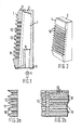
- a burner radiant or plaque is indicated at 1 and a box or case 2 forming a plenum chamber, impregnated tape 3 joining them.
- Conventional bonded fibre U.K. Patent No. 1 436 842
- radiant clay may be used for the plaque, and clay or steel for example for the box or case.
- the rest of the fire is conventional and not shown apart from a schematically indicated support frame 5 (Fig. 1) and gas jets 4.
- gas jets 4 Formed integrally with or fixed into the box or case are one or more venturis 6 for the jets 4, conventional in themselves.
- the fires use similar plaques fed from a plenum chamber 7, unitary as in Fig. 1 or divided into several separate sections with individually controlled gas jets, horizontally as indicated at 8 in Fig. 4 or vertically as in Fig. 5 by partitions 9.
- the plaques are divided into bars 10 and ported areas 11 with holes 12 for passage of the gas/air mixture.
- the holes are staggered in two rows and are at 3mm centres in the rows and 3mm row spacing, again on hole-centres.
- the bar spacing ridge to ridge is 12mm with a 2mm wide flat channel between bars, so the hole centres are actually in the flanks of the bars.
- the included angles between a normal to the plane of the radiant and the faces or flanks of the bars are 18° (upper flank) and 32° (lower flank), though these angles are only generally represented in the drawings.
- a lighting groove (unreferenced) is indicated in Fig. 4 centrally of the radiant and shown at the left of Fig. 3, and is in fact conveniently provided in all the designs, with an appropriate ignitor of conventional kind.
- heat exchangers are not shown as they are conventional, an advantage and indeed a considerable part of the point of the new units being that they can be used in existing gas fire designs as a straight replacement for the whole gas-supply/radiant assembly. Heat is produced over the sort of area people are used to and like, rather than in concentrated small areas such as surface combustion plaques give in uses when concentrated heat is required. The fire can be turned down without substantial loss in the glow, particularly in the designs where the plenum chamber is divided into sections. Designs such as those of Fig. 4 with horizontal division of the plenum chamber preserve the efficiency of heat exchange even at part fire.
- the radiant burner may be produced in several ways for instance (Figs. 1 and 2) with a "Tennaglo” (Trade Mark) bonded ceramic fibre radiant or plaque, made by filter casting, as the front face, and a pressed clay burner box. The two may be held together by glass fibre tape and fire resistant cement.
- the fibre is an alumino-silicate material made from fused kaolin and has the following properties:- Melting point 1760°C Continuous Service Temperature 1260°C Fibre Diameter, average 2.8 microns
- the slurry is made from 5 parts by weight of fibre, having lengths of about 15cm to 25cm, with two parts by weight of ball clay and 0.1 parts by weight of tricalcium phosphate flux as bonding agent.
- the ingredients are mixed together in a chopper mixer so as to produce a slurry in which the fibre lengths are for the most part between 0.025 and 1.25cm in length.
- the vacuum casting gives a soft, pliable green shape which is dried at 150°C and then fired in air at about 1050°C for half an hour, sufficient to bond the fibres.
- the radiant may be made of a traditional radiant clay, for example:- China Clay 39% Ball Clay 20% Fused Silica 30% Wood Flour 10% Bentonite 1%
- Ceramic box clay body is:- China Clay 39% Ball Clay 20% Molochite 30% Wood Flour 10% Bentonite 1%
- the radiant itself as seen in Fig. 8 has concentric ring-form bars each in four segments.
- the bars are referenced 21 (Fig. 9) and the ported areas between them 22.
- the radiant is held in a die cast metal base 23 by a bezel 24.
- An ignitor 25 is disposed centrally and flame from it travels through the radial gaps 26 between the bar segments.
- a plenum chamber formed by the base 23 is divided into four sections 27, as seen in Fig. 10 particularly, with venturis 28 and individual gas jets one of which is referenced 29. These gas jets are individually controlled in per se conventional manner at 30.
- the gas jets induce the air supply into the plenum chamber for passage of gas/air mixture through the part of the plaque supplied for combustion between the bars.
Landscapes
- Engineering & Computer Science (AREA)
- Chemical & Material Sciences (AREA)
- Combustion & Propulsion (AREA)
- Mechanical Engineering (AREA)
- General Engineering & Computer Science (AREA)
- Gas Burners (AREA)
Priority Applications (1)
| Application Number | Priority Date | Filing Date | Title |
|---|---|---|---|
| AT86308731T ATE76180T1 (de) | 1985-11-08 | 1986-11-10 | Strahler mit oberflaechenverbrennung. |
Applications Claiming Priority (4)
| Application Number | Priority Date | Filing Date | Title |
|---|---|---|---|
| GB858527595A GB8527595D0 (en) | 1985-11-08 | 1985-11-08 | Gas fire radiant burners |
| GB8527595 | 1985-11-08 | ||
| GB8620606 | 1986-08-26 | ||
| GB868620606A GB8620606D0 (en) | 1986-08-26 | 1986-08-26 | Radiant burner assembly |
Publications (2)
| Publication Number | Publication Date |
|---|---|
| EP0226324A1 true EP0226324A1 (de) | 1987-06-24 |
| EP0226324B1 EP0226324B1 (de) | 1992-05-13 |
Family
ID=26289986
Family Applications (1)
| Application Number | Title | Priority Date | Filing Date |
|---|---|---|---|
| EP86308731A Expired EP0226324B1 (de) | 1985-11-08 | 1986-11-10 | Strahler mit Oberflächenverbrennung |
Country Status (4)
| Country | Link |
|---|---|
| EP (1) | EP0226324B1 (de) |
| DE (1) | DE3685310D1 (de) |
| ES (1) | ES2031069T3 (de) |
| WO (1) | WO1987003067A1 (de) |
Cited By (5)
| Publication number | Priority date | Publication date | Assignee | Title |
|---|---|---|---|---|
| FR2639092A1 (fr) * | 1988-11-11 | 1990-05-18 | Samsung Electronics Co Ltd | Bruleur a gaz de type totalement primaire |
| EP0509538A2 (de) * | 1991-04-17 | 1992-10-21 | White Consolidated Industries, Inc. | Strahlungstechnologie |
| AT396819B (de) * | 1989-05-09 | 1993-12-27 | Vaillant Gmbh | Brennerplatte eines atmosphärischen brenners |
| ES2204212A1 (es) * | 2000-11-07 | 2004-04-16 | Nuevas Tecnicas Del Gas, S.L. | Sistema de quemador en circulos concentricos, con canales de aporte de aire hacia el centro. |
| ITTO20111001A1 (it) * | 2011-11-03 | 2013-05-04 | Indesit Co Spa | Bruciatore a gas di un piano cottura, in particolare ad uso domestico |
Families Citing this family (2)
| Publication number | Priority date | Publication date | Assignee | Title |
|---|---|---|---|---|
| IT1281854B1 (it) * | 1995-03-17 | 1998-03-03 | Over All S R L | Bruciatori a gas per piani di cottura in vetroceramico e per riscaldamento |
| CN104110715B (zh) * | 2014-07-19 | 2017-06-06 | 广东万和电气有限公司 | 红外辐射燃气灶的辐射器 |
Citations (11)
| Publication number | Priority date | Publication date | Assignee | Title |
|---|---|---|---|---|
| DE412163C (de) * | 1925-04-14 | Wilhelm Burg | Gasbrenner | |
| US2677366A (en) * | 1948-08-30 | 1954-05-04 | De Witt H Wyatt | Gas heater radiant |
| DE1116615B (de) * | 1956-06-15 | 1961-11-09 | Fr D Incandescence Par Le Gaz | Gasbeheizter Waermestrahler |
| GB926966A (en) * | 1960-08-16 | 1963-05-22 | Oatley Technical Dev | Gas-fire radiant |
| FR1408445A (fr) * | 1964-08-13 | 1965-08-13 | Osaka Gas Co Ltd | Dispositifs d'émission de rayons infrarouges |
| US3291188A (en) * | 1964-03-23 | 1966-12-13 | Partiot Maurice | Deep combustion radiant elements |
| GB1102105A (en) * | 1967-01-13 | 1968-02-07 | Gni I Pi Neftyanogo Mash | A panel-type gas burner |
| GB1328899A (en) * | 1970-10-19 | 1973-09-05 | Sagardui | Gas fired radiant plate burner for a stove |
| DE2633849A1 (de) * | 1974-08-24 | 1977-03-10 | Schwank Gmbh | Gasherd mit einem oder mehreren kochstellen-brennern |
| GB2010472A (en) * | 1977-11-25 | 1979-06-27 | Tennant & Sons Ltd | Gas-Fire Radiant |
| US4340357A (en) * | 1978-09-29 | 1982-07-20 | Rinnai Kabushiki Kaisha Rinnai Corporation | Infrared radiation gas burner plate |
-
1986
- 1986-11-10 EP EP86308731A patent/EP0226324B1/de not_active Expired
- 1986-11-10 DE DE8686308731T patent/DE3685310D1/de not_active Expired - Lifetime
- 1986-11-10 WO PCT/GB1986/000694 patent/WO1987003067A1/en unknown
- 1986-11-10 ES ES198686308731T patent/ES2031069T3/es not_active Expired - Lifetime
Patent Citations (11)
| Publication number | Priority date | Publication date | Assignee | Title |
|---|---|---|---|---|
| DE412163C (de) * | 1925-04-14 | Wilhelm Burg | Gasbrenner | |
| US2677366A (en) * | 1948-08-30 | 1954-05-04 | De Witt H Wyatt | Gas heater radiant |
| DE1116615B (de) * | 1956-06-15 | 1961-11-09 | Fr D Incandescence Par Le Gaz | Gasbeheizter Waermestrahler |
| GB926966A (en) * | 1960-08-16 | 1963-05-22 | Oatley Technical Dev | Gas-fire radiant |
| US3291188A (en) * | 1964-03-23 | 1966-12-13 | Partiot Maurice | Deep combustion radiant elements |
| FR1408445A (fr) * | 1964-08-13 | 1965-08-13 | Osaka Gas Co Ltd | Dispositifs d'émission de rayons infrarouges |
| GB1102105A (en) * | 1967-01-13 | 1968-02-07 | Gni I Pi Neftyanogo Mash | A panel-type gas burner |
| GB1328899A (en) * | 1970-10-19 | 1973-09-05 | Sagardui | Gas fired radiant plate burner for a stove |
| DE2633849A1 (de) * | 1974-08-24 | 1977-03-10 | Schwank Gmbh | Gasherd mit einem oder mehreren kochstellen-brennern |
| GB2010472A (en) * | 1977-11-25 | 1979-06-27 | Tennant & Sons Ltd | Gas-Fire Radiant |
| US4340357A (en) * | 1978-09-29 | 1982-07-20 | Rinnai Kabushiki Kaisha Rinnai Corporation | Infrared radiation gas burner plate |
Cited By (6)
| Publication number | Priority date | Publication date | Assignee | Title |
|---|---|---|---|---|
| FR2639092A1 (fr) * | 1988-11-11 | 1990-05-18 | Samsung Electronics Co Ltd | Bruleur a gaz de type totalement primaire |
| AT396819B (de) * | 1989-05-09 | 1993-12-27 | Vaillant Gmbh | Brennerplatte eines atmosphärischen brenners |
| EP0509538A2 (de) * | 1991-04-17 | 1992-10-21 | White Consolidated Industries, Inc. | Strahlungstechnologie |
| EP0509538A3 (en) * | 1991-04-17 | 1993-03-17 | White Consolidated Industries, Inc. | Emission technology |
| ES2204212A1 (es) * | 2000-11-07 | 2004-04-16 | Nuevas Tecnicas Del Gas, S.L. | Sistema de quemador en circulos concentricos, con canales de aporte de aire hacia el centro. |
| ITTO20111001A1 (it) * | 2011-11-03 | 2013-05-04 | Indesit Co Spa | Bruciatore a gas di un piano cottura, in particolare ad uso domestico |
Also Published As
| Publication number | Publication date |
|---|---|
| EP0226324B1 (de) | 1992-05-13 |
| WO1987003067A1 (en) | 1987-05-21 |
| ES2031069T3 (es) | 1992-12-01 |
| DE3685310D1 (de) | 1992-06-17 |
Similar Documents
| Publication | Publication Date | Title |
|---|---|---|
| US4569328A (en) | Efficient, low emissions gas range cooktop | |
| US7527495B2 (en) | Cooperating bridge burner system | |
| JPH10103621A (ja) | 調理面の下に取り付けられたガス輻射バーナを備えたガス調理装置へのガス供給調節及び運転圧力制御装置 | |
| CA2267869A1 (en) | Electric cooking oven with infrared gas broiler | |
| CA2058058A1 (en) | Gas burner with improved primary port arrangement | |
| EP0226324B1 (de) | Strahler mit Oberflächenverbrennung | |
| CN111288501B (zh) | 一种面积可调的防回火高效红外线燃气灶 | |
| US6148812A (en) | Cooking unit, such as a stove, for cooking food | |
| US2415223A (en) | Radiant provided with triangular pyramidal projection | |
| US7537447B2 (en) | Atmospheric gas burner made of biosoluble and gel-cast ceramic fibers | |
| US5032163A (en) | Horizontal flame burner for furnace floor radiant heater | |
| CN204786405U (zh) | 燃烧器及具有其的燃气灶 | |
| GB2267750A (en) | Cooking top | |
| AU738905B2 (en) | A gas hob | |
| US1998300A (en) | Gas burner | |
| CN2053721U (zh) | 燃气灶燃烧器 | |
| CN2388493Y (zh) | 食品烘焙炉的燃气燃烧器 | |
| CA1264260A (en) | Efficient, low emissions gas range cooktop | |
| CN212390360U (zh) | 一种复合红外线辐射板及其组合燃烧器 | |
| CN209926399U (zh) | 多眼煲仔炉 | |
| CN2665558Y (zh) | 高效节能炉头 | |
| CN2358359Y (zh) | 一种新型燃气灶 | |
| JPH045858Y2 (de) | ||
| CN2289972Y (zh) | 高效增温节能盘 | |
| JP2516184Y2 (ja) | 温風吹出口付レンジ |
Legal Events
| Date | Code | Title | Description |
|---|---|---|---|
| PUAI | Public reference made under article 153(3) epc to a published international application that has entered the european phase |
Free format text: ORIGINAL CODE: 0009012 |
|
| AK | Designated contracting states |
Kind code of ref document: A1 Designated state(s): AT BE CH DE ES FR GB GR IT LI LU NL SE |
|
| 17P | Request for examination filed |
Effective date: 19871221 |
|
| 17Q | First examination report despatched |
Effective date: 19880510 |
|
| RAP1 | Party data changed (applicant data changed or rights of an application transferred) |
Owner name: THERMAL CERAMICS LIMITED |
|
| GRAA | (expected) grant |
Free format text: ORIGINAL CODE: 0009210 |
|
| AK | Designated contracting states |
Kind code of ref document: B1 Designated state(s): AT BE CH DE ES FR GB GR IT LI LU NL SE |
|
| PG25 | Lapsed in a contracting state [announced via postgrant information from national office to epo] |
Ref country code: LI Effective date: 19920513 Ref country code: NL Effective date: 19920513 Ref country code: SE Effective date: 19920513 Ref country code: GR Free format text: LAPSE BECAUSE OF FAILURE TO SUBMIT A TRANSLATION OF THE DESCRIPTION OR TO PAY THE FEE WITHIN THE PRESCRIBED TIME-LIMIT Effective date: 19920513 Ref country code: AT Effective date: 19920513 Ref country code: CH Effective date: 19920513 Ref country code: BE Effective date: 19920513 Ref country code: IT Free format text: LAPSE BECAUSE OF FAILURE TO SUBMIT A TRANSLATION OF THE DESCRIPTION OR TO PAY THE FEE WITHIN THE PRE;WARNING: LAPSES OF ITALIAN PATENTS WITH EFFECTIVE DATE BEFORE 2007 MAY HAVE OCCURRED AT ANY TIME BEFORE 2007. THE CORRECT EFFECTIVE DATE MAY BE DIFFERENT FROM THE ONE RECORDED.SCRIBED TIME-LIMIT Effective date: 19920513 |
|
| REF | Corresponds to: |
Ref document number: 76180 Country of ref document: AT Date of ref document: 19920515 Kind code of ref document: T |
|
| REF | Corresponds to: |
Ref document number: 3685310 Country of ref document: DE Date of ref document: 19920617 |
|
| ET | Fr: translation filed | ||
| REG | Reference to a national code |
Ref country code: CH Ref legal event code: PL |
|
| NLV1 | Nl: lapsed or annulled due to failure to fulfill the requirements of art. 29p and 29m of the patents act | ||
| PG25 | Lapsed in a contracting state [announced via postgrant information from national office to epo] |
Ref country code: LU Free format text: LAPSE BECAUSE OF NON-PAYMENT OF DUE FEES Effective date: 19921130 |
|
| REG | Reference to a national code |
Ref country code: ES Ref legal event code: FG2A Ref document number: 2031069 Country of ref document: ES Kind code of ref document: T3 |
|
| PLBE | No opposition filed within time limit |
Free format text: ORIGINAL CODE: 0009261 |
|
| STAA | Information on the status of an ep patent application or granted ep patent |
Free format text: STATUS: NO OPPOSITION FILED WITHIN TIME LIMIT |
|
| 26N | No opposition filed | ||
| REG | Reference to a national code |
Ref country code: GB Ref legal event code: IF02 |
|
| PGFP | Annual fee paid to national office [announced via postgrant information from national office to epo] |
Ref country code: GB Payment date: 20021106 Year of fee payment: 17 |
|
| PGFP | Annual fee paid to national office [announced via postgrant information from national office to epo] |
Ref country code: FR Payment date: 20021108 Year of fee payment: 17 |
|
| PGFP | Annual fee paid to national office [announced via postgrant information from national office to epo] |
Ref country code: DE Payment date: 20021114 Year of fee payment: 17 |
|
| PGFP | Annual fee paid to national office [announced via postgrant information from national office to epo] |
Ref country code: ES Payment date: 20021209 Year of fee payment: 17 |
|
| PG25 | Lapsed in a contracting state [announced via postgrant information from national office to epo] |
Ref country code: GB Free format text: LAPSE BECAUSE OF NON-PAYMENT OF DUE FEES Effective date: 20031110 |
|
| PG25 | Lapsed in a contracting state [announced via postgrant information from national office to epo] |
Ref country code: ES Free format text: LAPSE BECAUSE OF NON-PAYMENT OF DUE FEES Effective date: 20031111 |
|
| PG25 | Lapsed in a contracting state [announced via postgrant information from national office to epo] |
Ref country code: DE Free format text: LAPSE BECAUSE OF NON-PAYMENT OF DUE FEES Effective date: 20040602 |
|
| GBPC | Gb: european patent ceased through non-payment of renewal fee |
Effective date: 20031110 |
|
| PG25 | Lapsed in a contracting state [announced via postgrant information from national office to epo] |
Ref country code: FR Free format text: LAPSE BECAUSE OF NON-PAYMENT OF DUE FEES Effective date: 20040730 |
|
| REG | Reference to a national code |
Ref country code: FR Ref legal event code: ST |
|
| REG | Reference to a national code |
Ref country code: ES Ref legal event code: FD2A Effective date: 20031111 |
|
| APAH | Appeal reference modified |
Free format text: ORIGINAL CODE: EPIDOSCREFNO |