EP0225140A2 - Stromversorgungssteueranlage für elektronisches Steuersystem - Google Patents
Stromversorgungssteueranlage für elektronisches Steuersystem Download PDFInfo
- Publication number
- EP0225140A2 EP0225140A2 EP86309123A EP86309123A EP0225140A2 EP 0225140 A2 EP0225140 A2 EP 0225140A2 EP 86309123 A EP86309123 A EP 86309123A EP 86309123 A EP86309123 A EP 86309123A EP 0225140 A2 EP0225140 A2 EP 0225140A2
- Authority
- EP
- European Patent Office
- Prior art keywords
- control system
- electronic control
- self
- electric power
- automobile
- Prior art date
- Legal status (The legal status is an assumption and is not a legal conclusion. Google has not performed a legal analysis and makes no representation as to the accuracy of the status listed.)
- Granted
Links
Images


Classifications
-
- F—MECHANICAL ENGINEERING; LIGHTING; HEATING; WEAPONS; BLASTING
- F16—ENGINEERING ELEMENTS AND UNITS; GENERAL MEASURES FOR PRODUCING AND MAINTAINING EFFECTIVE FUNCTIONING OF MACHINES OR INSTALLATIONS; THERMAL INSULATION IN GENERAL
- F16H—GEARING
- F16H61/00—Control functions within control units of change-speed- or reversing-gearings for conveying rotary motion ; Control of exclusively fluid gearing, friction gearing, gearings with endless flexible members or other particular types of gearing
- F16H61/12—Detecting malfunction or potential malfunction, e.g. fail safe; Circumventing or fixing failures
-
- B—PERFORMING OPERATIONS; TRANSPORTING
- B60—VEHICLES IN GENERAL
- B60R—VEHICLES, VEHICLE FITTINGS, OR VEHICLE PARTS, NOT OTHERWISE PROVIDED FOR
- B60R16/00—Electric or fluid circuits specially adapted for vehicles and not otherwise provided for; Arrangement of elements of electric or fluid circuits specially adapted for vehicles and not otherwise provided for
-
- B—PERFORMING OPERATIONS; TRANSPORTING
- B60—VEHICLES IN GENERAL
- B60K—ARRANGEMENT OR MOUNTING OF PROPULSION UNITS OR OF TRANSMISSIONS IN VEHICLES; ARRANGEMENT OR MOUNTING OF PLURAL DIVERSE PRIME-MOVERS IN VEHICLES; AUXILIARY DRIVES FOR VEHICLES; INSTRUMENTATION OR DASHBOARDS FOR VEHICLES; ARRANGEMENTS IN CONNECTION WITH COOLING, AIR INTAKE, GAS EXHAUST OR FUEL SUPPLY OF PROPULSION UNITS IN VEHICLES
- B60K23/00—Arrangement or mounting of control devices for vehicle transmissions, or parts thereof, not otherwise provided for
-
- F—MECHANICAL ENGINEERING; LIGHTING; HEATING; WEAPONS; BLASTING
- F16—ENGINEERING ELEMENTS AND UNITS; GENERAL MEASURES FOR PRODUCING AND MAINTAINING EFFECTIVE FUNCTIONING OF MACHINES OR INSTALLATIONS; THERMAL INSULATION IN GENERAL
- F16D—COUPLINGS FOR TRANSMITTING ROTATION; CLUTCHES; BRAKES
- F16D48/00—External control of clutches
- F16D48/06—Control by electric or electronic means, e.g. of fluid pressure
- F16D48/066—Control of fluid pressure, e.g. using an accumulator
-
- F—MECHANICAL ENGINEERING; LIGHTING; HEATING; WEAPONS; BLASTING
- F16—ENGINEERING ELEMENTS AND UNITS; GENERAL MEASURES FOR PRODUCING AND MAINTAINING EFFECTIVE FUNCTIONING OF MACHINES OR INSTALLATIONS; THERMAL INSULATION IN GENERAL
- F16D—COUPLINGS FOR TRANSMITTING ROTATION; CLUTCHES; BRAKES
- F16D2500/00—External control of clutches by electric or electronic means
- F16D2500/30—Signal inputs
- F16D2500/306—Signal inputs from the engine
- F16D2500/3067—Speed of the engine
-
- F—MECHANICAL ENGINEERING; LIGHTING; HEATING; WEAPONS; BLASTING
- F16—ENGINEERING ELEMENTS AND UNITS; GENERAL MEASURES FOR PRODUCING AND MAINTAINING EFFECTIVE FUNCTIONING OF MACHINES OR INSTALLATIONS; THERMAL INSULATION IN GENERAL
- F16D—COUPLINGS FOR TRANSMITTING ROTATION; CLUTCHES; BRAKES
- F16D2500/00—External control of clutches by electric or electronic means
- F16D2500/30—Signal inputs
- F16D2500/306—Signal inputs from the engine
- F16D2500/3069—Engine ignition switch
-
- F—MECHANICAL ENGINEERING; LIGHTING; HEATING; WEAPONS; BLASTING
- F16—ENGINEERING ELEMENTS AND UNITS; GENERAL MEASURES FOR PRODUCING AND MAINTAINING EFFECTIVE FUNCTIONING OF MACHINES OR INSTALLATIONS; THERMAL INSULATION IN GENERAL
- F16D—COUPLINGS FOR TRANSMITTING ROTATION; CLUTCHES; BRAKES
- F16D2500/00—External control of clutches by electric or electronic means
- F16D2500/30—Signal inputs
- F16D2500/308—Signal inputs from the transmission
- F16D2500/30806—Engaged transmission ratio
-
- F—MECHANICAL ENGINEERING; LIGHTING; HEATING; WEAPONS; BLASTING
- F16—ENGINEERING ELEMENTS AND UNITS; GENERAL MEASURES FOR PRODUCING AND MAINTAINING EFFECTIVE FUNCTIONING OF MACHINES OR INSTALLATIONS; THERMAL INSULATION IN GENERAL
- F16D—COUPLINGS FOR TRANSMITTING ROTATION; CLUTCHES; BRAKES
- F16D2500/00—External control of clutches by electric or electronic means
- F16D2500/30—Signal inputs
- F16D2500/31—Signal inputs from the vehicle
- F16D2500/3108—Vehicle speed
-
- F—MECHANICAL ENGINEERING; LIGHTING; HEATING; WEAPONS; BLASTING
- F16—ENGINEERING ELEMENTS AND UNITS; GENERAL MEASURES FOR PRODUCING AND MAINTAINING EFFECTIVE FUNCTIONING OF MACHINES OR INSTALLATIONS; THERMAL INSULATION IN GENERAL
- F16D—COUPLINGS FOR TRANSMITTING ROTATION; CLUTCHES; BRAKES
- F16D2500/00—External control of clutches by electric or electronic means
- F16D2500/70—Details about the implementation of the control system
- F16D2500/704—Output parameters from the control unit; Target parameters to be controlled
- F16D2500/70402—Actuator parameters
- F16D2500/7041—Position
-
- F—MECHANICAL ENGINEERING; LIGHTING; HEATING; WEAPONS; BLASTING
- F16—ENGINEERING ELEMENTS AND UNITS; GENERAL MEASURES FOR PRODUCING AND MAINTAINING EFFECTIVE FUNCTIONING OF MACHINES OR INSTALLATIONS; THERMAL INSULATION IN GENERAL
- F16D—COUPLINGS FOR TRANSMITTING ROTATION; CLUTCHES; BRAKES
- F16D2500/00—External control of clutches by electric or electronic means
- F16D2500/70—Details about the implementation of the control system
- F16D2500/704—Output parameters from the control unit; Target parameters to be controlled
- F16D2500/70402—Actuator parameters
- F16D2500/70418—Current
-
- F—MECHANICAL ENGINEERING; LIGHTING; HEATING; WEAPONS; BLASTING
- F16—ENGINEERING ELEMENTS AND UNITS; GENERAL MEASURES FOR PRODUCING AND MAINTAINING EFFECTIVE FUNCTIONING OF MACHINES OR INSTALLATIONS; THERMAL INSULATION IN GENERAL
- F16D—COUPLINGS FOR TRANSMITTING ROTATION; CLUTCHES; BRAKES
- F16D2500/00—External control of clutches by electric or electronic means
- F16D2500/70—Details about the implementation of the control system
- F16D2500/704—Output parameters from the control unit; Target parameters to be controlled
- F16D2500/70402—Actuator parameters
- F16D2500/7042—Voltage
-
- F—MECHANICAL ENGINEERING; LIGHTING; HEATING; WEAPONS; BLASTING
- F16—ENGINEERING ELEMENTS AND UNITS; GENERAL MEASURES FOR PRODUCING AND MAINTAINING EFFECTIVE FUNCTIONING OF MACHINES OR INSTALLATIONS; THERMAL INSULATION IN GENERAL
- F16H—GEARING
- F16H61/00—Control functions within control units of change-speed- or reversing-gearings for conveying rotary motion ; Control of exclusively fluid gearing, friction gearing, gearings with endless flexible members or other particular types of gearing
- F16H61/12—Detecting malfunction or potential malfunction, e.g. fail safe; Circumventing or fixing failures
- F16H2061/122—Avoiding failures by using redundant parts
-
- F—MECHANICAL ENGINEERING; LIGHTING; HEATING; WEAPONS; BLASTING
- F16—ENGINEERING ELEMENTS AND UNITS; GENERAL MEASURES FOR PRODUCING AND MAINTAINING EFFECTIVE FUNCTIONING OF MACHINES OR INSTALLATIONS; THERMAL INSULATION IN GENERAL
- F16H—GEARING
- F16H61/00—Control functions within control units of change-speed- or reversing-gearings for conveying rotary motion ; Control of exclusively fluid gearing, friction gearing, gearings with endless flexible members or other particular types of gearing
- F16H61/12—Detecting malfunction or potential malfunction, e.g. fail safe; Circumventing or fixing failures
- F16H2061/1232—Bringing the control into a predefined state, e.g. giving priority to particular actuators or gear ratios
-
- F—MECHANICAL ENGINEERING; LIGHTING; HEATING; WEAPONS; BLASTING
- F16—ENGINEERING ELEMENTS AND UNITS; GENERAL MEASURES FOR PRODUCING AND MAINTAINING EFFECTIVE FUNCTIONING OF MACHINES OR INSTALLATIONS; THERMAL INSULATION IN GENERAL
- F16H—GEARING
- F16H61/00—Control functions within control units of change-speed- or reversing-gearings for conveying rotary motion ; Control of exclusively fluid gearing, friction gearing, gearings with endless flexible members or other particular types of gearing
- F16H61/12—Detecting malfunction or potential malfunction, e.g. fail safe; Circumventing or fixing failures
- F16H2061/1256—Detecting malfunction or potential malfunction, e.g. fail safe; Circumventing or fixing failures characterised by the parts or units where malfunctioning was assumed or detected
- F16H2061/1292—Detecting malfunction or potential malfunction, e.g. fail safe; Circumventing or fixing failures characterised by the parts or units where malfunctioning was assumed or detected the failing part is the power supply, e.g. the electric power supply
Definitions
- This invention relates to a power supply control device for use with an electronic control system, and more particularly to a power supply control device having a self-holding circuit, for use with an automotive electronic control system.
- a power supply control device for supplying electric power to an electronic control system, such as a computer for controlling devices on an automobile; characterised by main supply means for supplying electric power from a power supply on the automobile to at least the electronic control system; a self-holding circuit separate from the main supply means for supplying electric power to the electronic control system when the electric power supplied by the main supply means to the electronic control system is cut off; and power cutoff means for cutting off the electric power supplied by the self-holding circuit to the electronic control system when a job to be executed by the electronic control system is finished after the electric power supplied by the main supply means to the electronic control system has been cut off.
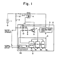
- FIG. 1 shows an embodiment of the present invention.
- a battery 1 for use on an automobile comprises an ordinary lead storage battery having an output voltage of 12, 24 or 48 volts.
- a power supply switch 2 preferably in the form of a key switch, is turned on when it is in an "accessory” position and in a "power-on” or “start” position.
- the power supply switch 2 will hereinafter be referred to as a "key switch”.
- the battery l and the key switch 2 are coupled to fuses 3-l, 3-2, and the fuse 3-2 is coupled to a power supply relay 4 for self-holding a power supply circuit.
- An electronic control system 6 includes a constant-voltage regulated power supply 5 for converting the output voltage of l2, 24, or 48 volts from the battery l to a voltage of 5.5 volts, for example, which is required to drive an electronic control system (described later).
- the electronic control system 6 also includes a driver transistor 7 for energizing the power supply relay 4, a microcomputer 8 comprising a read-only memory 8a, a central processing unit (CPU) 8b, an input/output buffer 8c, and an input/output interface 8d, and diodes l0, ll, l2 for preventing currents from flowing back therethrough.
- the circuit arrangement shown in Fig. l has a self-holding means for continuously supplying electric power to the electronic control system 6 when the key switch 2 is opened, and a means for turning off the self-holding means to stop operation of the power supply of the electronic control system 6 when the electronic control system 6 has completed a predetermined sequence of operation after detecting when the electric power supplied to the automobile was cut off inadvertently or intentionally.
- the self-holding circuit will be described below.
- the voltage of the battery l is applied via the key switch 2 and the diode l0 to the constant-voltage regulated power supply 5 to energize the electronic control system 6.
- the voltage is impressed via the diode ll on the base of the transistor 7 to energize the transistor 7, thus energizing the relay 4 to close its contacts, whereupon the voltage from the battery l is also applied through the relay 4 to the constant-voltage regulated power supply 5.
- the microcomputer 8 is supplied with signals from various sensors through the input/output interface 8d and the input/output buffer 8c.
- the CPU 8b executes various programs stored in the ROM 8a to supply various control signals to different devices on the automobile through the input/output buffer 8c and the input/output interface 8d.
- the input/output buffer 8c issues a signal for turning on the driver transistor 7. This signal is applied via the diode l2 to the base of the driver transistor 7 to render the latter conductive. A current now flows through the coil of the relay 4 to close the contacts thereof, so that the voltage from the battery l is held and applied to the constant-voltage regulated power supply 5.
- the current supplied to the power supply 5 via the diode l0 and the current supplied to the base of the driver transistor 7 through the diode ll are cut off.
- the transistor 7 remains energized via the input/output buffer 8c and the diode l2 to keep the relay 4 actuated, the voltage from the battery l is continuously applied to the electronic control system 6.
- the electronic control system 6 is therefore prevented from being de-energized even when the key switch 2 is turned off erroneously or the fuse 3-l melts.
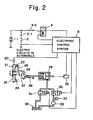
- Fig. 2 shows another embodiment of the present invention
- Fig. 2A illustrates the internal arrangement of an electronic control system shown in Fig. 2.
- the means for turning off the self-holding means to cut off the electric power supplied to the electronic control system will be described in detail with reference to Figs. 2 and 2A.
- a clutch mechanism 2l for selectively transmitting engine power comprises a flywheel 22, a driven plate 23, a pressure plate 24, a clutch lever 25, a release bearing 26, a release lever 27, and a return spring 28 which normally urges the clutch mechanism connected when there is no fluid pressure supplied to a clutch actuator 29 from a clutch disconnecting valve 30.
- Designated at 3l is a clutch connecting valve 3l, an accumulator 32, a fluid pressure source 33 comprising a pump, 34 a working fluid tank, and 35 a stroke sensor for detecting the operation stroke of the clutch actuator 29. A detected signal from the stroke sensor 35 is applied to the electronic control system 6.
- the clutch disconnecting valve 30 and the clutch connecting valve 3l are opened and closed under the control of the electroinc control system 6 for disconnecting and connecting the clutch mechanism 2l.
- a rotation signal issued by an engine rotation sensor 20 and indicative of the rotation of the engine is delivered to the electronic control system 6.
- the self-holding means which has kept the electronic control system 6 energized is turned off to cut off the electric power supplied to the electronic control system 6.
- the self-holding means and the means for turning off the self-holding means are effective in preventing the clutch mechanism from being connected in the absence of the electric power even if the key switch 2 is turned off before the engine is stopped, so that the automobile is prevented from moving unexpectedly.
- the means for turning off the self-holding means has been described above with reference to Figs. 2 and 2A in which the clutch mechanism is connected after confirming that the engine has been stopped.
- the means for turning off the self-holding means may be actuated by applying a gear position signal from the gear transmission to the electronic control system after confirming that the clutch mechanism is disconnected after the engine has been stopped, the gear transmission is then shifted into a first (low) gear position or a reverse gear position, and thereafter the clutch mechanism is connected.
- Figs. 3(a) and 3(b) show operation sequences for the embodiment of Fig. l.
- Fig. 3(a) shows an operation sequence to be executed after the key switch is turned on.
- the key switch 2 When the key switch 2 is turned on, the electric power from the battery l is supplied through the diode l0 to the constant-voltage regulated power supply 5 in a step l, and the CPU 8b starts operating in a step 2. Then, a command is delivered via the input-output buffer 8c and the diode l2 to the driver transistor 7 to energize the relay 4 for thereby self-holding the electric power supplied to the electronic control system 6 in a step 3.
- the step 3 is followed by normal control.
- Fig. 3(b) illustrates an operation sequence to be executed when the key switch is turned off erroneously or the fuse is caused to melt.
- the key switch 2 is turned off erroneously or the fuse melts in a step 4
- normal control is carried out in a step 5. If the automobile is brought into a safe condition, such as when the clutch mechanism is connected after the engine has stopped, as indicated by an external input applied to the input/output interface 8d, then control goes from the step 4 to a step 6 in which the driver transistor 7 is rendered non-conductive through the input/output buffer 8c and the diode l2 to de-energize the coil of the relay 4, thereby turning off the self-holding means in a step 6.
- the electric power supplied to the electronic control system 6 is cut off in a step 7.
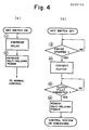
- Figs. 4(a) and 4(b) illustrate operation sequences for the embodiment of Figs. 2 and 2A.
- Fig. 4(a) shows an operation sequence to be executed after the key switch is turned on.
- the coil of the relay 4 is energized by the electronic control system 6 to connect the contacts of the relay 4 in a step ll.
- the electric power supplied to the electronic control system 6 is held in a step l2 to allow the electronic control system 6 to effect normal control.
- Fig. 4(b) illustrates an operation sequence to be carried out when the key switch is turned off.
- the electronic control system 6 reads in the signal from the engine rotation sensor 20 in a step l3. After confirming that the engine is stopped, the electronic control system 6 issues a command to enable the clutch actuator 29 to connect the clutch mechanism 2l in a step l4. Then, the electronic control system 6 reads in the signal from the stroke sensor 35 to determine the condition of the clutch mechanism 2l in a step l5. If the clutch mechanism 2l is fully connected, then control proceeds to a step l6 in which the relay 4 is de-energized to cut off the electric power supplied to the electronic control system 6 through the self-holding means, whereupon the operation sequence is completed.
- Fig. 5 is illustrative of an equivalent circuit of the embodiment of Fig. l, the circuit being in the form of a logic circuit.
- the circuit includes an AND gate l3 representative of the relay 4, and an OR gate l4 indicative of the diodes ll, l2 and the driver transistor 7.
- H high level
- L low level
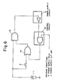
- Fig. 6 shows an equivalent circuit, in the form of a logic circuit, of the embodiment illustrated in Fig. 2.
- the circuit includes an AND gate l3 representative of the relay 4, and an OR gate l4 indicative of the diodes ll, l2 and the driver transistor 7, as with the equivalent circuit of Fig. 5.
- H and L inputs applied to the control circuit 8′ indicate whether the self-holding means is to remain turned on or be turned off.
- the relay 4 is replaced with a transistor 7a for controlling a large current.
- Fig. 7 which are identical to those of Fig. l are denoted by identical reference characters and will not be described in detail.
- the cathodes of the diodes ll, l2 for preventing a current from flowing back are connected to the base of the transistor 7a, with its collector coupled to the fuse 3-2 and the emitter to the constant-voltage regulated power supply 5.
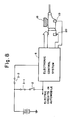
- Fig. 8 shows a modification of the embodiment of Fig. l, employed for controlling a gear transmission.
- l8 is a gear transmission control unit, l9 an automobile speed sensor mounted on a gear transmission, and 20 an engine rotation sensor.
- the electronic control system 6 applies a command for controlling gear positions to the gear transmission control unit l8, and is supplied with detected signals from the respective automobile speed sensor l9 and the engine rotation sensor 20.
- the electronic control system 6 When the key switch 2 is operated in error or the fuse is caused to melt while the automobile is running, the electronic control system 6 holds the electric power supplied through the self-holding means, and also reads in the signals from the engine rotation sensor l9 and the automobile speed sensor 20. Until these signals indicate that the engine and the automobile are stopped, the electronic control system 6 continuously delivers an appropriate signal to the gear transmission control unit l8 to control the running of the automobile, while preventing undesired accidents from occurring due to an unexpected cutoff of the electric power during travel of the automobile.
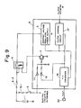
- Fig. 9 shows a modification of the embodiment of Fig. 2, employed for clutch control.
- a frequency-to-voltage converter l6 serves to convert the frequency of a pulse signal from the engine rotation sensor 20 to a voltage.
- a clutch control circuit l7 controls the clutch actuator 29 (Fig. 2) and also controls the driver transistor 7 in response to a signal from the stroke sensor 35.
- the frequency-to-voltage converter l6 receives the signal from the engine rotation sensor 20 and converts the frequency thereof to a voltage proportional thereto. Therefore, while the engine is in rotation, the frequency-to-voltage converter l6 produces an output voltage corresponding to the rotation of the engine to render the driver transistor 7 conductive for thereby keeping the electric power supplied to the electronic control system 6.
- the relay 4 is de-energized by the frequency-to-voltage converter l6 and the clutch control circuit l7 via the driver transistor 7. Accordingly, the electric power supplied to the electronic control system 6 is cut off.
Landscapes
- Engineering & Computer Science (AREA)
- General Engineering & Computer Science (AREA)
- Mechanical Engineering (AREA)
- Physics & Mathematics (AREA)
- Fluid Mechanics (AREA)
- Combustion & Propulsion (AREA)
- Chemical & Material Sciences (AREA)
- Transportation (AREA)
- Hydraulic Clutches, Magnetic Clutches, Fluid Clutches, And Fluid Joints (AREA)
- Arrangement And Mounting Of Devices That Control Transmission Of Motive Force (AREA)
- Control Of Transmission Device (AREA)
- Control Of Vehicle Engines Or Engines For Specific Uses (AREA)
- Power Sources (AREA)
Applications Claiming Priority (2)
| Application Number | Priority Date | Filing Date | Title |
|---|---|---|---|
| JP60263460A JPS62122827A (ja) | 1985-11-22 | 1985-11-22 | 電子制御装置における電源制御装置 |
| JP263460/85 | 1985-11-22 |
Publications (3)
| Publication Number | Publication Date |
|---|---|
| EP0225140A2 true EP0225140A2 (de) | 1987-06-10 |
| EP0225140A3 EP0225140A3 (en) | 1988-07-06 |
| EP0225140B1 EP0225140B1 (de) | 1992-04-01 |
Family
ID=17389813
Family Applications (1)
| Application Number | Title | Priority Date | Filing Date |
|---|---|---|---|
| EP86309123A Expired - Lifetime EP0225140B1 (de) | 1985-11-22 | 1986-11-21 | Stromversorgungssteueranlage für elektronisches Steuersystem |
Country Status (5)
| Country | Link |
|---|---|
| US (1) | US4807135A (de) |
| EP (1) | EP0225140B1 (de) |
| JP (1) | JPS62122827A (de) |
| KR (1) | KR910004599B1 (de) |
| DE (1) | DE3684673D1 (de) |
Cited By (15)
| Publication number | Priority date | Publication date | Assignee | Title |
|---|---|---|---|---|
| EP0296774A2 (de) * | 1987-06-20 | 1988-12-28 | Isuzu Motors Limited | Elektronisches Steuersystem für ein automatisches Getriebe eines Fahrzeugs |
| DE3915269A1 (de) * | 1988-05-11 | 1989-11-23 | Fuji Heavy Ind Ltd | Stromversorgungsgeraet fuer ein diagnosegeraet |
| EP0349992A2 (de) * | 1988-07-04 | 1990-01-10 | Mazda Motor Corporation | Hinterraddrehvorrichtung für ein Kraftfahrzeug |
| EP0445430A2 (de) * | 1990-03-01 | 1991-09-11 | Blaupunkt-Werke GmbH | Netzteil für die Stromversorgung einer Steuerschaltung in einem Tonbandgerät |
| EP0492103A2 (de) * | 1990-12-22 | 1992-07-01 | Robert Bosch Gmbh | Einrichtung zur Spannungsversorgung bei Geräten mit Nachlauf |
| FR2685142A1 (fr) * | 1991-12-17 | 1993-06-18 | Bosch Gmbh Robert | Montage d'un circuit pour commander le fonctionnement de repos d'un dispositif de commande d'un vehicule automobile. |
| EP0574743A2 (de) * | 1992-06-13 | 1993-12-22 | Claas OHG beschränkt haftende offene Handelsgesellschaft | Gepufferte Spannungsversorgung für Bordelektronik |
| GB2305791A (en) * | 1995-09-27 | 1997-04-16 | Allan George Alexander Guthrie | Vehicle electrical system with a plurality of different voltages |
| FR2750187A1 (fr) * | 1996-05-14 | 1997-12-26 | Luk Getriebe Systeme Gmbh | Dispositif d'actionnement automatise d'un systeme de transmission de couple |
| FR2815301A1 (fr) * | 2000-10-06 | 2002-04-19 | Luk Lamellen & Kupplungsbau | Appareil de commande |
| CN103507729A (zh) * | 2013-09-22 | 2014-01-15 | 重庆长安汽车股份有限公司 | 电动汽车整车控制器电源自保持系统 |
| CN103863223A (zh) * | 2012-12-17 | 2014-06-18 | 重庆长安汽车股份有限公司 | 一种电动汽车整车控制器唤醒系统 |
| WO2015039658A1 (de) * | 2013-09-19 | 2015-03-26 | Schaeffler Technologies AG & Co. KG | Verfahren zum versorgen eines steuergeräts |
| EP2933151A1 (de) * | 2014-04-17 | 2015-10-21 | Kawasaki Jukogyo Kabushiki Kaisha | Fahrzeug und stromversorgungsvorrichtung dafür |
| CN105711520A (zh) * | 2016-04-27 | 2016-06-29 | 安徽江淮汽车股份有限公司 | 一种整车控制器的电源管理电路及其控制方法 |
Families Citing this family (20)
| Publication number | Priority date | Publication date | Assignee | Title |
|---|---|---|---|---|
| JPH0767900B2 (ja) * | 1987-08-25 | 1995-07-26 | 本田技研工業株式会社 | 車輌盗難防止装置 |
| JPH01156153A (ja) * | 1987-12-11 | 1989-06-19 | Diesel Kiki Co Ltd | 車両用電子コントロールユニット |
| US4992951A (en) * | 1988-04-29 | 1991-02-12 | Chrysler Corporation | Utilization of a reset output of a regulator as a system low-voltage inhibit |
| US4991096A (en) * | 1988-04-29 | 1991-02-05 | Chrysler Corporation | Shutdown relay driver circuit |
| FR2651890B1 (fr) * | 1989-09-11 | 1991-12-13 | Siemens Bendix Automotive Elec | Dispositif de detection et de discrimination de defauts de fonctionnement d'un circuit d'alimentation electrique. |
| JPH0550950U (ja) * | 1991-12-04 | 1993-07-02 | 澤藤電機株式会社 | エンジン発電機用制御装置 |
| GB9219101D0 (en) * | 1992-09-09 | 1992-10-21 | Automotive Products Plc | A clutch control system |
| NO970288L (no) * | 1996-01-29 | 1997-07-30 | Luk Getriebe Systeme Gmbh | Betjeningsanordning |
| JP3650456B2 (ja) * | 1996-03-04 | 2005-05-18 | 矢崎総業株式会社 | 車両用電源分配装置 |
| US5936317A (en) * | 1996-04-09 | 1999-08-10 | Harness System Technologies Research, Ltd. | Power supply device for vehicle |
| GB2347476B (en) * | 1996-05-14 | 2001-02-14 | Luk Getriebe Systeme Gmbh | Apparatus for actuating torque transmitting systems |
| US6052646A (en) * | 1998-04-15 | 2000-04-18 | Magellan Dis, Inc. | Vehicle navigation system with improved powerup performance |
| JP3886741B2 (ja) * | 2001-06-07 | 2007-02-28 | 三菱電機株式会社 | 内燃機関制御装置のための電源システム |
| US7765043B2 (en) | 2003-05-12 | 2010-07-27 | Toyota Jidosha Kabushiki Kaisha | Power supply control apparatus and method |
| US7124005B2 (en) * | 2003-08-07 | 2006-10-17 | Denso Corporation | Electronic control unit having hold circuit and method therefor |
| JP2005323470A (ja) * | 2004-05-11 | 2005-11-17 | Atex Co Ltd | 電動車の制動制御装置 |
| JP5602687B2 (ja) * | 2004-07-02 | 2014-10-08 | ヤマハ発動機株式会社 | 車両 |
| US8055441B2 (en) * | 2007-07-27 | 2011-11-08 | Mitac International Corporation | Supplemental powered information receiver |
| KR101305672B1 (ko) * | 2011-07-28 | 2013-09-09 | 기아자동차주식회사 | 자동화 변속장치의 제어장치 전원회로 |
| JP6277862B2 (ja) * | 2014-05-22 | 2018-02-14 | マツダ株式会社 | 自動変速機の制御装置 |
Citations (1)
| Publication number | Priority date | Publication date | Assignee | Title |
|---|---|---|---|---|
| GB2154765A (en) * | 1984-02-07 | 1985-09-11 | Nissan Motor | Output speed dependent throttle control system for internal combustion engine |
Family Cites Families (9)
| Publication number | Priority date | Publication date | Assignee | Title |
|---|---|---|---|---|
| JPS5183335A (ja) * | 1975-01-20 | 1976-07-21 | Nissan Motor | Jidoshayodengensochi |
| US4258421A (en) * | 1978-02-27 | 1981-03-24 | Rockwell International Corporation | Vehicle monitoring and recording system |
| US4484307A (en) * | 1979-05-09 | 1984-11-20 | F.M.E. Corporation | Electronic postage meter having improved security and fault tolerance features |
| JPS56101039A (en) * | 1980-01-18 | 1981-08-13 | Nissan Motor Co Ltd | Automatic system for operating vehicle at constant speed |
| FR2480000A1 (fr) * | 1980-04-03 | 1981-10-09 | Renault | Commande electronique pour transmission automatique de vehicule automobile utilisant un microcalculateur |
| EP0045142B1 (de) * | 1980-07-24 | 1985-03-27 | The Secretary of State for Defence in Her Britannic Majesty's Government of the United Kingdom of Great Britain and | Adsorption an einem Aktivkohlegewebe |
| US4491112A (en) * | 1982-01-13 | 1985-01-01 | Nissan Motor Company, Limited | Failsafe for an engine control |
| JPS5974152U (ja) * | 1982-11-12 | 1984-05-19 | 三菱自動車工業株式会社 | 自動車用ワイパ装置 |
| JPS59120524A (ja) * | 1982-12-28 | 1984-07-12 | Isuzu Motors Ltd | 電子制御式変速機の変速操作方法 |
-
1985
- 1985-11-22 JP JP60263460A patent/JPS62122827A/ja active Granted
-
1986
- 1986-11-21 EP EP86309123A patent/EP0225140B1/de not_active Expired - Lifetime
- 1986-11-21 DE DE8686309123T patent/DE3684673D1/de not_active Expired - Fee Related
- 1986-11-21 US US06/933,130 patent/US4807135A/en not_active Expired - Fee Related
- 1986-11-22 KR KR1019860009887A patent/KR910004599B1/ko not_active IP Right Cessation
Patent Citations (1)
| Publication number | Priority date | Publication date | Assignee | Title |
|---|---|---|---|---|
| GB2154765A (en) * | 1984-02-07 | 1985-09-11 | Nissan Motor | Output speed dependent throttle control system for internal combustion engine |
Non-Patent Citations (4)
| Title |
|---|
| PATENT ABSTRACTS OF JAPAN, vol. 7, no. 42 (P-177)[1187], 19th February 1983; & JP-A-57 191 724 (SHARP K.K.) 25-11-1982 * |
| PATENT ABSTRACTS OF JAPAN, vol. 8, no. 259 (P-317)[1696], 28th November 1984; & JP-A-59 132 018 (FUJITSU K.K.) 30-07-1984 * |
| PATENT ABSTRACTS OF JAPAN, vol. 9, no. 25 (M-355)[1748], 2nd February 1985; & JP-A-59 171 743 (MITSUBISHI DENKI K.K.) 28-09-1984 * |
| PATENT ABSTRACTS OF JAPAN, vol. 9, no. 25 (M-355)[1748], 2nd February 1985; & JP-A-59 171 744 (MITSUBISHI DENKI K.K.) 28-09-1984 * |
Cited By (28)
| Publication number | Priority date | Publication date | Assignee | Title |
|---|---|---|---|---|
| EP0296774A3 (en) * | 1987-06-20 | 1989-10-18 | Isuzu Motors Limited | Electronic control system for automatic vehicle transmission |
| EP0296774A2 (de) * | 1987-06-20 | 1988-12-28 | Isuzu Motors Limited | Elektronisches Steuersystem für ein automatisches Getriebe eines Fahrzeugs |
| DE3915269A1 (de) * | 1988-05-11 | 1989-11-23 | Fuji Heavy Ind Ltd | Stromversorgungsgeraet fuer ein diagnosegeraet |
| GB2219153A (en) * | 1988-05-11 | 1989-11-29 | Fuji Heavy Ind Ltd | Power supply for fault diagnosis apparatus of vehicle air bag equipment |
| EP0349992A2 (de) * | 1988-07-04 | 1990-01-10 | Mazda Motor Corporation | Hinterraddrehvorrichtung für ein Kraftfahrzeug |
| EP0349992A3 (en) * | 1988-07-04 | 1990-11-07 | Mazda Motor Corporation | Rear wheel turning system for a vehicle |
| EP0445430A2 (de) * | 1990-03-01 | 1991-09-11 | Blaupunkt-Werke GmbH | Netzteil für die Stromversorgung einer Steuerschaltung in einem Tonbandgerät |
| EP0445430A3 (en) * | 1990-03-01 | 1993-11-10 | Blaupunkt Werke Gmbh | Power supply for a control circuit of a tape recorder |
| EP0492103A3 (de) * | 1990-12-22 | 1994-08-31 | Bosch Gmbh Robert | |
| EP0492103A2 (de) * | 1990-12-22 | 1992-07-01 | Robert Bosch Gmbh | Einrichtung zur Spannungsversorgung bei Geräten mit Nachlauf |
| FR2685142A1 (fr) * | 1991-12-17 | 1993-06-18 | Bosch Gmbh Robert | Montage d'un circuit pour commander le fonctionnement de repos d'un dispositif de commande d'un vehicule automobile. |
| DE4143674B4 (de) * | 1991-12-17 | 2006-03-30 | Robert Bosch Gmbh | Schaltungsanordnung zur Steuerung des Nachlaufs eines Steuergeräts in einem Kraftfahrzeug |
| EP0574743A2 (de) * | 1992-06-13 | 1993-12-22 | Claas OHG beschränkt haftende offene Handelsgesellschaft | Gepufferte Spannungsversorgung für Bordelektronik |
| EP0574743A3 (de) * | 1992-06-13 | 1994-12-07 | Claas Ohg | Gepufferte Spannungsversorgung für Bordelektronik. |
| GB2305791A (en) * | 1995-09-27 | 1997-04-16 | Allan George Alexander Guthrie | Vehicle electrical system with a plurality of different voltages |
| US5821634A (en) * | 1995-09-27 | 1998-10-13 | Guthrie; Allan George Alexander | Electrical circuit to reduce voltage supplied to sensitive components from elevated voltage supply of a vehicle battery |
| GB2305791B (en) * | 1995-09-27 | 1999-11-17 | Allan George Alexander Guthrie | Electrical circuits |
| FR2750187A1 (fr) * | 1996-05-14 | 1997-12-26 | Luk Getriebe Systeme Gmbh | Dispositif d'actionnement automatise d'un systeme de transmission de couple |
| FR2815301A1 (fr) * | 2000-10-06 | 2002-04-19 | Luk Lamellen & Kupplungsbau | Appareil de commande |
| CN103863223A (zh) * | 2012-12-17 | 2014-06-18 | 重庆长安汽车股份有限公司 | 一种电动汽车整车控制器唤醒系统 |
| CN103863223B (zh) * | 2012-12-17 | 2016-02-03 | 重庆长安汽车股份有限公司 | 一种电动汽车整车控制器唤醒系统 |
| WO2015039658A1 (de) * | 2013-09-19 | 2015-03-26 | Schaeffler Technologies AG & Co. KG | Verfahren zum versorgen eines steuergeräts |
| CN105556182A (zh) * | 2013-09-19 | 2016-05-04 | 舍弗勒技术股份两合公司 | 用于对控制装置供电的方法 |
| CN105556182B (zh) * | 2013-09-19 | 2018-04-24 | 舍弗勒技术股份两合公司 | 保持机动车安全行驶状态的方法和控制执行器的控制装置 |
| CN103507729A (zh) * | 2013-09-22 | 2014-01-15 | 重庆长安汽车股份有限公司 | 电动汽车整车控制器电源自保持系统 |
| CN103507729B (zh) * | 2013-09-22 | 2015-10-07 | 重庆长安汽车股份有限公司 | 电动汽车整车控制器电源自保持系统 |
| EP2933151A1 (de) * | 2014-04-17 | 2015-10-21 | Kawasaki Jukogyo Kabushiki Kaisha | Fahrzeug und stromversorgungsvorrichtung dafür |
| CN105711520A (zh) * | 2016-04-27 | 2016-06-29 | 安徽江淮汽车股份有限公司 | 一种整车控制器的电源管理电路及其控制方法 |
Also Published As
| Publication number | Publication date |
|---|---|
| US4807135A (en) | 1989-02-21 |
| KR910004599B1 (ko) | 1991-07-08 |
| JPH0554459B2 (de) | 1993-08-12 |
| EP0225140B1 (de) | 1992-04-01 |
| JPS62122827A (ja) | 1987-06-04 |
| DE3684673D1 (de) | 1992-05-07 |
| KR870004859A (ko) | 1987-06-02 |
| EP0225140A3 (en) | 1988-07-06 |
Similar Documents
| Publication | Publication Date | Title |
|---|---|---|
| EP0225140B1 (de) | Stromversorgungssteueranlage für elektronisches Steuersystem | |
| US4561527A (en) | Electric parking brake system for a vehicle | |
| US4117903A (en) | Vehicle speed control system | |
| US20040104619A1 (en) | Electro mechanical brake, control device and control methods | |
| US6084315A (en) | System for operating a control device in a motor vehicle | |
| EP0809765B1 (de) | Kupplungssteuerung mit integriertem sicherheitssystem, elektischer notsteuereinrichtung und verfahren zur steuerung | |
| US6594572B1 (en) | Device for authorizing an unrestricted operating mode of a vehicle control device in the event of a failure of the ignition signal | |
| US3593815A (en) | System for automatically operating parking brake for automobiles | |
| US4987872A (en) | Process and device for monitoring a set value indicator of a drive motor of a motor vehicle | |
| US3941204A (en) | Engine automatic control system for vehicles | |
| JPS6115300B2 (de) | ||
| US4532432A (en) | Control circuit system for automobiles | |
| US4802710A (en) | Electric switching device | |
| JPH11148415A (ja) | 自動車を停止させるための方法および制御システム | |
| US6176810B1 (en) | Starter interlock system for a motor vehicle with an automatic gear box | |
| US4074226A (en) | Brake malfunction warning and indicating system for automobiles | |
| US5025379A (en) | System and method for automatically controlling vehicle speed to desired cruise speed using microcomputer | |
| CN102481934A (zh) | 用于使车辆开动的方法和系统 | |
| EP0050874B1 (de) | Steuervorrichtung für einen Servolenkungsmotor eines batteriegetriebenen Fahrzeuges | |
| US4290045A (en) | Brake system warning circuit | |
| DE19925758A1 (de) | Gangschaltung für Kraftfahrzeuge | |
| US5517065A (en) | Automotive digital light control circuit with light bus monitor and windshield wiper light control circuit | |
| JPS631001B2 (de) | ||
| EP0049535A2 (de) | Automatische Steueranlage zum Bedienen der Kupplung eines Fahrzeuges | |
| JPH0428161Y2 (de) |
Legal Events
| Date | Code | Title | Description |
|---|---|---|---|
| PUAI | Public reference made under article 153(3) epc to a published international application that has entered the european phase |
Free format text: ORIGINAL CODE: 0009012 |
|
| AK | Designated contracting states |
Kind code of ref document: A2 Designated state(s): DE FR GB IT SE |
|
| PUAL | Search report despatched |
Free format text: ORIGINAL CODE: 0009013 |
|
| AK | Designated contracting states |
Kind code of ref document: A3 Designated state(s): DE FR GB IT SE |
|
| 17P | Request for examination filed |
Effective date: 19890104 |
|
| 17Q | First examination report despatched |
Effective date: 19900906 |
|
| GRAA | (expected) grant |
Free format text: ORIGINAL CODE: 0009210 |
|
| AK | Designated contracting states |
Kind code of ref document: B1 Designated state(s): DE FR GB IT SE |
|
| REF | Corresponds to: |
Ref document number: 3684673 Country of ref document: DE Date of ref document: 19920507 |
|
| ITF | It: translation for a ep patent filed |
Owner name: JACOBACCI & PERANI S.P.A. |
|
| ET | Fr: translation filed | ||
| PLBI | Opposition filed |
Free format text: ORIGINAL CODE: 0009260 |
|
| 26 | Opposition filed |
Opponent name: ROBERT BOSCH GMBH Effective date: 19921224 |
|
| EAL | Se: european patent in force in sweden |
Ref document number: 86309123.7 |
|
| PLBN | Opposition rejected |
Free format text: ORIGINAL CODE: 0009273 |
|
| STAA | Information on the status of an ep patent application or granted ep patent |
Free format text: STATUS: OPPOSITION REJECTED |
|
| 27O | Opposition rejected |
Effective date: 19950718 |
|
| REG | Reference to a national code |
Ref country code: GB Ref legal event code: IF02 |
|
| PGFP | Annual fee paid to national office [announced via postgrant information from national office to epo] |
Ref country code: FR Payment date: 20041010 Year of fee payment: 19 |
|
| PGFP | Annual fee paid to national office [announced via postgrant information from national office to epo] |
Ref country code: GB Payment date: 20041014 Year of fee payment: 19 |
|
| PGFP | Annual fee paid to national office [announced via postgrant information from national office to epo] |
Ref country code: SE Payment date: 20041020 Year of fee payment: 19 Ref country code: DE Payment date: 20041020 Year of fee payment: 19 |
|
| APAH | Appeal reference modified |
Free format text: ORIGINAL CODE: EPIDOSCREFNO |
|
| PG25 | Lapsed in a contracting state [announced via postgrant information from national office to epo] |
Ref country code: IT Free format text: LAPSE BECAUSE OF NON-PAYMENT OF DUE FEES Effective date: 20051121 Ref country code: GB Free format text: LAPSE BECAUSE OF NON-PAYMENT OF DUE FEES Effective date: 20051121 |
|
| PG25 | Lapsed in a contracting state [announced via postgrant information from national office to epo] |
Ref country code: SE Free format text: LAPSE BECAUSE OF NON-PAYMENT OF DUE FEES Effective date: 20051122 |
|
| PG25 | Lapsed in a contracting state [announced via postgrant information from national office to epo] |
Ref country code: DE Free format text: LAPSE BECAUSE OF NON-PAYMENT OF DUE FEES Effective date: 20060601 |
|
| EUG | Se: european patent has lapsed | ||
| GBPC | Gb: european patent ceased through non-payment of renewal fee |
Effective date: 20051121 |
|
| PG25 | Lapsed in a contracting state [announced via postgrant information from national office to epo] |
Ref country code: FR Free format text: LAPSE BECAUSE OF NON-PAYMENT OF DUE FEES Effective date: 20060731 |
|
| REG | Reference to a national code |
Ref country code: FR Ref legal event code: ST Effective date: 20060731 |