EP0224377A2 - Geschwindigkeitsmessaufnehmer - Google Patents
Geschwindigkeitsmessaufnehmer Download PDFInfo
- Publication number
- EP0224377A2 EP0224377A2 EP86309056A EP86309056A EP0224377A2 EP 0224377 A2 EP0224377 A2 EP 0224377A2 EP 86309056 A EP86309056 A EP 86309056A EP 86309056 A EP86309056 A EP 86309056A EP 0224377 A2 EP0224377 A2 EP 0224377A2
- Authority
- EP
- European Patent Office
- Prior art keywords
- coils
- magnetic
- speed detecting
- coil
- magnetic circuit
- Prior art date
- Legal status (The legal status is an assumption and is not a legal conclusion. Google has not performed a legal analysis and makes no representation as to the accuracy of the status listed.)
- Granted
Links
Images

Classifications
-
- G—PHYSICS
- G01—MEASURING; TESTING
- G01P—MEASURING LINEAR OR ANGULAR SPEED, ACCELERATION, DECELERATION, OR SHOCK; INDICATING PRESENCE, ABSENCE, OR DIRECTION, OF MOVEMENT
- G01P3/00—Measuring linear or angular speed; Measuring differences of linear or angular speeds
- G01P3/64—Devices characterised by the determination of the time taken to traverse a fixed distance
-
- G—PHYSICS
- G01—MEASURING; TESTING
- G01P—MEASURING LINEAR OR ANGULAR SPEED, ACCELERATION, DECELERATION, OR SHOCK; INDICATING PRESENCE, ABSENCE, OR DIRECTION, OF MOVEMENT
- G01P3/00—Measuring linear or angular speed; Measuring differences of linear or angular speeds
- G01P3/42—Devices characterised by the use of electric or magnetic means
- G01P3/50—Devices characterised by the use of electric or magnetic means for measuring linear speed
- G01P3/52—Devices characterised by the use of electric or magnetic means for measuring linear speed by measuring amplitude of generated current or voltage
Definitions
- the present invention relates to a speed detecting device to be used for detecting the moving speed of an optical pickup which is moved radially relative to a compact disc (CD).
- CD compact disc
- a pick-up drive device with a linear motor as a driving source it is well known for a pick-up drive device with a linear motor as a driving source to be used for moving an optical pick-up radially relative to an optical disk.
- a speed detecting device for detecting the moving speed of the optical pick-up is provided corresponding to the pick-up drive device and high-accuracy positioning of the optical pick-up is performed by controlling the linear motor in dependance upon the moving speed signal detected by the speed detecting device.
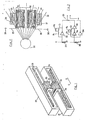
- Figure 9 shows a conventional pick-up, pick-up drive device and speed detecting device.
- Numeral 1 designates an optical pick-up main body, the upper face of which faces an optical disk (not shown in the drawing), and which body is mounted on guide shafts 3 and 4 and is movable in the direction of the arrows A and B on bearings 2 (only one of which is shown in the drawing).
- the linear motor comprises a coil unit, for example a bobbin 6b wound with a drive coil 6a, attached to the support plate 5, and a box-shaped magnetic member 6c or yoke, one side of which passes freely through the bobbin 6b.
- a permanent magnet 6d is attached to the inside of the magnetic member 6c, facing the drive coil 6a, to form a magnetic circuit.
- a coil unit for detecting the optical pick-up moving speed for example a bobbin 8 wound with a detecting coil 7, and one side of a box-shaped magnetic member 9 or yoke passes freely through the bobbin 8.
- a magnet 10 is attached to the inside of the magnetic member 9, facing the detecting coil 7, to form a magnetic circuit.
- the drive coil 6a is provided in a magnetic circuit, formed by the magnetic member 6c and the magnet 6d and, when a current is applied to the drive coil 6a, an energizing force conforming to Fleming's left hand rule is generated.
- the optical pick-up main body is thus moved in the direction of arrows A and B through the bobbin 6b, according to the direction of the current, and laser beams are radiated on to the optical disk (not shown in the drawing) through a focusing lens 1a.
- the support plate 5 with the attached bobbin 8 wound with the detecting coil 7 moves in the same direction.
- the detecting coil 7 is provided in a magnetic circuit formed with the magnetic member 9 and the magnet 10 and cuts the magnetic lines of flux therebetween, an inductive electromotive force is generated in the coil in proportion to the moving speed, conforming to Fleming's so-called right hand rule, and a detecting section (not shown in the drawing) detects the moving speed of the optical pick-up main body 1 from changes in the electromotive force.
- the detecting section controls application of the current to the drive coil 6a of the linear motor 6 and performs position control of the optical pick-up main body.
- the drive section of the optical pick-up main body 1 is rotated by the inertial force of the drive system around the axis of inertia positioned between the drive coil 6a and the detecting coil 7.
- the drive coil 6a and the detecting coil 7 have a speed component (speed vector) in opposite directions one from the other.
- the phase of the control signal fed back from the detecting coil 7 to the drive coil 6 is reversed and the drive system oscillates resulting in degradation of control.
- the present invention seeks to provide a speed detecting device so designed as to facilitate miniaturization and improve the detecting accuracy.
- a speed detecting device comprises a plurality of coils and a magnetic circuit arrangement, the coils and the magnetic circuit arrangement being positioned relative to one another such that magnetic lines of flux of the magnetic circuit arrangement pass through the coils, and such that relative movement at the speed to be detected can be effected between the coils and said magnetic circuit arrangement, so that the coils cross lines of flux and electrical signals are generated therein representative of the speed of relative movement, and the coils being arranged such that an extraneous magnetic field passing through the coils will produce an error signal with an electrical sense relative to the speed detecting signal in one coil which is opposite to that produced in the other coil or in other coils.
- Figure 1 of the drawings shows part of a speed detecting device according to one embodiment of the present invention.
- the numerals 20 and 21 designate two magnetic members, a first magnetic member and a second magnetic member, which may be the only two or two of a larger number of magnetic members.
- the first and the second magnetic members 20 and 21 are substantially symmetrically positioned relative to an external magnetic field generating section 22 and first and second magnets 23 and 24, each magnetized to provide two poles (N, S), are attached each to one side portion of the inside of each of the magnetic members 20 and 21 to form two magnetic circuits.
- first and second bobbins 25 and 26 each constituting a coil unit, and mounted so that they can be moved simultaneously in the direction of the arrows C and D.
- the first and second bobbins 25 and 26 are linked to the optical pick-up 1 (see Fig. 9) and carry respectively, first and second coils 27 and 28 which are wound in reverse direction with respect to each other.
- One end of the first coil 27 is connected to one end of the second coil 2 and to earth.
- the other ends, output ends 29 and 30, are connected to a detecting section through, for example, a mixing unit not shown in the drawing.
- the first and the second coils 27 and 28 of the first and the second bobbin 25 and 26 are simultaneously moved in the same direction with respect to the first and second magnets 23 and 24 upon movement of the pick-up.
- the momentary induced electromotive forces in the coils are input to the mixing unit (not shown in the drawing) from each output end (29, 30), mixed and fed as input to a detecting section (not shown in the drawing) to detect the moving speed.
- the speed detecting device has a construction, in which the first and the second coils 27 and 28, one of which is wound in reverse direction, can be moved simultaneously and the disturbing effect of the leakage flux 31 from the external flux generating section 22 can be securely prevented. It is possible, therefore, to perform a speed detection of high-precision and also to provide the device at a position adjacent to the external flux generating section 22, so that it is possible to promote more miniaturization than with a conventional known device.
- a balance adjusting equalizer circuit can be added to the output ends 29 and 30 of the first and second coil 27 and 28, as shown in Figure 3, so that imbalance of the first and second coils 27 and 28 can be corrected.
- variable resistance 33 is connected to the output end 29 of the first coil 27 through a frequency characteristic correction circuit comprising an operational amplifier 32, resistances R1 and R2, and a capacitor C1, and the other end of the variable resistance 33 is connected to the output end 30 of the second coil 28 through a frequency characteristic correction circuit comprising an operational amplifier 34, inverting amplifier 35, resistances R3 and R4, and a capacitor C2 to provide a balance adjustment of displacement of the positions of the first and the second bobbins 25 and 26.
- the first and the second bobbins 25 and 26 are described as being moved.
- the present invention is not limited to this. It is possible to fix the first and the second bobbins 25 and 26 and to make the first and the second magnets 23 and 24 movable.
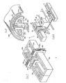
- magnetic circuit and coil assemblies of the speed detecting device may alternatively, for example, be constructed in accordance with one of Figures 4 to 8.
- Figures 4 to 8 the same elements as in Figure 1 are given like reference characters and have the same function and therefore, detailed description is not required.
- the device for further promoting miniaturization, is designated so that first and second bobbins 25a and 26a are connected by a connection plate 36a.
- the device is designed so that a support plate 36c is provided on first and a second magnetic members 20c and 21c for an external field generating section 22c, such as a linear motor, as well as for first and second bobbins 25c and 26c.
- an external field generating section 22c such as a linear motor
- the device for improving the efficiency, is designed so that arcuate first and second magnets 23d and 24d, first and second bobbins 25d and 26d, and first and second coils 27 and 28d are provided corresponding to first and second magnetic members 20d and 21d to increase the effective length of the coils.
- reference 36d designates a support connecting the first and second bobbins 25d and 26d.
- the number of coils is not limited to two, but substantially the same effect can be obtained by providing a plurality of coils of suitable dimensions so that they can be moved relatively and simultaneously and by winding at least one of the coils in reverse direction to the other coils.
- the present invention can provide a speed detecting device so designed as to facilitate miniaturization and improve detection accuracy.
Landscapes
- Physics & Mathematics (AREA)
- General Physics & Mathematics (AREA)
- Moving Of The Head For Recording And Reproducing By Optical Means (AREA)
- Moving Of Head For Track Selection And Changing (AREA)
- Reciprocating, Oscillating Or Vibrating Motors (AREA)
Applications Claiming Priority (2)
| Application Number | Priority Date | Filing Date | Title |
|---|---|---|---|
| JP60259436A JPS62119461A (ja) | 1985-11-19 | 1985-11-19 | 速度検出装置 |
| JP259436/85 | 1985-11-19 |
Publications (3)
| Publication Number | Publication Date |
|---|---|
| EP0224377A2 true EP0224377A2 (de) | 1987-06-03 |
| EP0224377A3 EP0224377A3 (en) | 1989-02-15 |
| EP0224377B1 EP0224377B1 (de) | 1992-01-15 |
Family
ID=17334061
Family Applications (1)
| Application Number | Title | Priority Date | Filing Date |
|---|---|---|---|
| EP86309056A Expired - Lifetime EP0224377B1 (de) | 1985-11-19 | 1986-11-19 | Geschwindigkeitsmessaufnehmer |
Country Status (5)
| Country | Link |
|---|---|
| US (1) | US4906923A (de) |
| EP (1) | EP0224377B1 (de) |
| JP (1) | JPS62119461A (de) |
| KR (1) | KR900002512B1 (de) |
| DE (1) | DE3683463D1 (de) |
Cited By (1)
| Publication number | Priority date | Publication date | Assignee | Title |
|---|---|---|---|---|
| EP0417956A3 (en) * | 1989-09-05 | 1991-07-10 | Hugh-Peter Granville Kelly | Improvements in or relating to the control of linear motors |
Families Citing this family (4)
| Publication number | Priority date | Publication date | Assignee | Title |
|---|---|---|---|---|
| US5257255A (en) * | 1988-03-30 | 1993-10-26 | Canon Denshi Kabushiki Kaisha | Recording and/or reproducing apparatus with sensor for detecting head speed or acceleration |
| JPH11260003A (ja) * | 1998-03-12 | 1999-09-24 | Teac Corp | ディスク装置 |
| US6963733B2 (en) * | 2001-10-31 | 2005-11-08 | Telefonaktiebolaget L M Ericsson (Publ) | Method and apparatus for reducing the effect of AGC switching transients |
| DE10342562A1 (de) * | 2003-09-15 | 2005-04-21 | Siemens Ag | Regelungseinrichtung bzw. Regelung einer elektrischen Maschine |
Family Cites Families (12)
| Publication number | Priority date | Publication date | Assignee | Title |
|---|---|---|---|---|
| US3440532A (en) * | 1965-05-07 | 1969-04-22 | Skinner Precision Ind Inc | Speed sensor for linear induction motors |
| SU197708A1 (ru) * | 1966-03-23 | 1973-01-08 | ВСЕСОЮЗНАЯ IШ.-уул -•'УУк''ГГ<(.?>&'?3! tHihl^it-Abfr:'.- EUi.'tiБ^'-|€:ЛИО^ТКА (ТЕРЛ10 | |
| GB1306022A (de) * | 1971-01-19 | 1973-02-07 | ||
| US3755745A (en) * | 1971-08-20 | 1973-08-28 | Itt | Noise discrimination apparatus |
| SU523354A1 (ru) * | 1974-12-17 | 1976-07-30 | Предприятие П/Я В-8337 | Индукционный датчик скорости |
| US4161693A (en) * | 1977-03-09 | 1979-07-17 | Airpax Electronics, Inc. | Clamped input common mode rejection amplifier |
| JPS54146607A (en) * | 1978-05-08 | 1979-11-16 | Sony Corp | Tone-arm device |
| US4260914A (en) * | 1979-03-28 | 1981-04-07 | Digital Equipment Corporation | Differential linear velocity transducer |
| GB2088646B (en) * | 1980-10-24 | 1984-09-12 | Sony Corp | Pick-up assemblies for disc players |
| JPS5911764A (ja) * | 1982-07-12 | 1984-01-21 | Nippon Soken Inc | 電磁駆動装置 |
| US4622516A (en) * | 1983-06-16 | 1986-11-11 | Digital Equipment Corporation | Magnetic tachometer for disk drives |
| US4544890A (en) * | 1983-11-07 | 1985-10-01 | Magnetic Peripherals Inc. | Flat coil velocity transducer |
-
1985
- 1985-11-19 JP JP60259436A patent/JPS62119461A/ja active Pending
-
1986
- 1986-11-19 EP EP86309056A patent/EP0224377B1/de not_active Expired - Lifetime
- 1986-11-19 KR KR1019860009776A patent/KR900002512B1/ko not_active Expired
- 1986-11-19 DE DE8686309056T patent/DE3683463D1/de not_active Expired - Lifetime
-
1988
- 1988-10-07 US US07/256,063 patent/US4906923A/en not_active Expired - Fee Related
Cited By (3)
| Publication number | Priority date | Publication date | Assignee | Title |
|---|---|---|---|---|
| EP0417956A3 (en) * | 1989-09-05 | 1991-07-10 | Hugh-Peter Granville Kelly | Improvements in or relating to the control of linear motors |
| US5091665A (en) * | 1989-09-05 | 1992-02-25 | Kelly H P G | Linear motors |
| AU649405B2 (en) * | 1989-09-05 | 1994-05-26 | Linear Drives Limited | Improvements in or relating to the control of linear motors |
Also Published As
| Publication number | Publication date |
|---|---|
| EP0224377B1 (de) | 1992-01-15 |
| DE3683463D1 (de) | 1992-02-27 |
| KR870005253A (ko) | 1987-06-05 |
| KR900002512B1 (ko) | 1990-04-16 |
| US4906923A (en) | 1990-03-06 |
| EP0224377A3 (en) | 1989-02-15 |
| JPS62119461A (ja) | 1987-05-30 |
Similar Documents
| Publication | Publication Date | Title |
|---|---|---|
| US5536983A (en) | Linear motor | |
| US4861138A (en) | Device for driving optical parts of an optical pickup | |
| EP0273367A2 (de) | Steuerungsgerät für Objektivlinse | |
| US20010026528A1 (en) | Apparatus for driving a lens for use with a disk player | |
| KR900006182B1 (ko) | 전기 기계 변환기 | |
| KR960000832B1 (ko) | 리니어 액추에이터 | |
| JP2765633B2 (ja) | 光学系支持装置 | |
| JP2004005813A (ja) | 光ヘッド装置及びそれを用いた光再生装置 | |
| KR20010013817A (ko) | 콤팩트한 액추에이터를 갖는 렌즈계를 구비한 광학 주사장치 | |
| EP0224377A2 (de) | Geschwindigkeitsmessaufnehmer | |
| JPS6242352B2 (de) | ||
| JP3489470B2 (ja) | レンズ鏡筒 | |
| KR100295972B1 (ko) | 스캐닝장치및스캐닝장치를포함하는광학플레이어 | |
| JPH08168232A (ja) | リニアエンコーダ装置 | |
| EP1931185A1 (de) | Leiterplatte für einen optischen Lesekopf mit verschränkter Neigung und darauf angebrachte Fokuswindungen | |
| JP2001273656A (ja) | 光ピックアップの対物レンズ駆動装置 | |
| JP4064731B2 (ja) | 対物レンズ駆動装置、光ピックアップ装置及び光ディスク装置 | |
| JP2575354B2 (ja) | 対物レンズ駆動装置 | |
| JPS6139241A (ja) | 対物レンズ駆動装置 | |
| JP2713827B2 (ja) | 対物レンズ駆動装置 | |
| JP2749614B2 (ja) | 対物レンズ駆動装置 | |
| JPH08203105A (ja) | 対物レンズ駆動装置 | |
| JPH0240138A (ja) | 対物レンズ駆動装置 | |
| JPH04310653A (ja) | 光ディスクドライブ装置 | |
| JPS6117227A (ja) | 光ピツクアツプ |
Legal Events
| Date | Code | Title | Description |
|---|---|---|---|
| PUAI | Public reference made under article 153(3) epc to a published international application that has entered the european phase |
Free format text: ORIGINAL CODE: 0009012 |
|
| 17P | Request for examination filed |
Effective date: 19861208 |
|
| AK | Designated contracting states |
Kind code of ref document: A2 Designated state(s): DE GB |
|
| PUAL | Search report despatched |
Free format text: ORIGINAL CODE: 0009013 |
|
| AK | Designated contracting states |
Kind code of ref document: A3 Designated state(s): DE GB |
|
| 17Q | First examination report despatched |
Effective date: 19900605 |
|
| GRAA | (expected) grant |
Free format text: ORIGINAL CODE: 0009210 |
|
| AK | Designated contracting states |
Kind code of ref document: B1 Designated state(s): DE GB |
|
| REF | Corresponds to: |
Ref document number: 3683463 Country of ref document: DE Date of ref document: 19920227 |
|
| PLBE | No opposition filed within time limit |
Free format text: ORIGINAL CODE: 0009261 |
|
| STAA | Information on the status of an ep patent application or granted ep patent |
Free format text: STATUS: NO OPPOSITION FILED WITHIN TIME LIMIT |
|
| 26N | No opposition filed | ||
| PGFP | Annual fee paid to national office [announced via postgrant information from national office to epo] |
Ref country code: GB Payment date: 19941109 Year of fee payment: 9 |
|
| PGFP | Annual fee paid to national office [announced via postgrant information from national office to epo] |
Ref country code: DE Payment date: 19941123 Year of fee payment: 9 |
|
| PG25 | Lapsed in a contracting state [announced via postgrant information from national office to epo] |
Ref country code: GB Effective date: 19951119 |
|
| GBPC | Gb: european patent ceased through non-payment of renewal fee |
Effective date: 19951119 |
|
| PG25 | Lapsed in a contracting state [announced via postgrant information from national office to epo] |
Ref country code: DE Effective date: 19960801 |