EP0223097B1 - Interrupteur à bascule - Google Patents
Interrupteur à bascule Download PDFInfo
- Publication number
- EP0223097B1 EP0223097B1 EP86114670A EP86114670A EP0223097B1 EP 0223097 B1 EP0223097 B1 EP 0223097B1 EP 86114670 A EP86114670 A EP 86114670A EP 86114670 A EP86114670 A EP 86114670A EP 0223097 B1 EP0223097 B1 EP 0223097B1
- Authority
- EP
- European Patent Office
- Prior art keywords
- housing
- rocker arm
- switch
- membrane
- fact
- Prior art date
- Legal status (The legal status is an assumption and is not a legal conclusion. Google has not performed a legal analysis and makes no representation as to the accuracy of the status listed.)
- Expired - Lifetime
Links
Images

Classifications
-
- H—ELECTRICITY
- H01—ELECTRIC ELEMENTS
- H01H—ELECTRIC SWITCHES; RELAYS; SELECTORS; EMERGENCY PROTECTIVE DEVICES
- H01H23/00—Tumbler or rocker switches, i.e. switches characterised by being operated by rocking an operating member in the form of a rocker button
- H01H23/02—Details
- H01H23/04—Cases; Covers
- H01H23/06—Dustproof, splashproof, drip-proof, waterproof, or flameproof casings
- H01H23/065—Casings hermetically closed by a diaphragm through which passes an actuating member
Definitions
- the invention relates to a rocker switch according to the preamble of claim 1.
- a rocker arm is pivotally mounted in a housing, the shaft part of which projects out of a housing opening for actuation.
- Miniaturized toggle switches are increasingly being attached to circuit board using mechanical soldering techniques, the flux used in soldering being able to penetrate into the switch housing from below along the contact pins protruding from the housing and also from above via the housing opening, from which the Kinphebel shaft part protrudes and can cause contact or operating problems.
- rocker arm switches of the type briefly described at the outset have been developed, with the rocker arm serving to actuate a rocker switch in a known rocker arm switch construction of this type and the sealing membrane has the shape of an annular disk which is clamped between the wall and the housing opening and the rocker arm shaft part is.
- rocker arm switches which have a ball joint-like rocker arm hub in the region of the pivot axis of the rocker arm, which is opposite the housing opening of the switch housing is sealed by the O-ring.
- the frictional forces between the sealing ring and the counter sealing surfaces in turn cause an increase in the actuating forces to be applied. If foreign bodies enter between the O-ring and the counter sealing surfaces, an adequate seal of the switch housing cannot be guaranteed. Otherwise, this type of construction requires an essentially rotationally symmetrical shape of the components to be sealed against one another.
- a rocker arm switch of the type mentioned is known from GB-A-1192437, in which the rocker arm is pivotably inserted into a housing via a membrane and the actuating shaft projecting outwards can be actuated via a cross lever.
- US-A-3,041,430 describes a further rocker arm which can be pivoted from the outside in any direction on a diaphragm joint which is arranged in a housing attachment, while the inner end projecting into the housing actuates the corresponding switching contacts.
- US-A-2,768,258 shows a further rocker arm, which is sealed against the housing by means of a membrane with a double U-shaped cross section and is pivotably mounted via an actuating shaft.
- the invention has for its object to design a rocker arm switch of the type described in such a way that the sealing membrane seal between the switch housing opening and the rocker arm stem part emerging therefrom essentially does not impair the smooth operation of the switch and a reliable seal is achieved even if the inner diameter the housing opening is not very much larger than the opposite outer diameter of the rocker arm shaft part, so a disc-shaped sealing membrane cannot be attached.
- an outer housing jacket is placed over the housing, which, by engagement with the outer wall of the inverting membrane, presses the outer edge thereof against the annular groove or undercut of the housing.
- the radially inner edge of the everting membrane lies close to the pivot axis of the rocker arm and engages in particular a groove or a shoulder of the rocker arm shaft part.
- the radially outer edge of the inverted membrane can be held or clamped in a groove or undercut in the plane of the radially inner edge on the wall of the housing opening.
- a practical, very advantageous embodiment of the rocker arm switch specified here provides that the switching elements are spring spiders attached to a hub of the rocker arm, these spring spiders preferably having contact spring arms of different radial lengths projecting from the side of the rocker arm shaft part such that the rocker arm - The area of the rocker arm facing the shaft part is kept clear for the everting membrane. In this way, it is possible to arrange the radially inner edge of the everting membrane on the rocker arm shaft part very close to its pivot axis, so that when the toggle lever is actuated, the everting membrane undergoes minimal deformation.
- the radially outer edge of the inverted membrane can be clamped between an outwardly opening groove of the housing, which is preferably formed in two parts, and an outer housing jacket.
- the housing side away from the housing opening can finally be sealed or encapsulated with plastic or plastic adhesive, so that the switch housing interior is hermetically sealed and is also protected against moisture, access to foreign bodies and a corrosive ambient atmosphere during the entire operating life or service life of the switch.
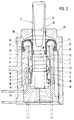
- the toggle switch specified here has a housing consisting of two housing halves 1 and 2, in which bearings are provided at opposite points of the housing halves, in which bearing pins of a rocker arm hub 3 of a rocker arm 4 are mounted. From the rocker arm hub 3, a rocker arm shaft part 5 protrudes radially outward through a housing opening 6, so that the rocker arm hub 3 can be rotated counterclockwise or clockwise about the pivot axis or rocker axis by actuating the rocker arm shaft part 5.
- contact spring spiders 8 and 9 are fastened on both sides via rivet-like pins 7, the outlines of which can be seen in FIG. 1 of the drawing.
- the contact spring spiders 8 and 9 have on a base 10 with reference to the illustration of FIG. 1, right and left attached, arcuate contact spring arms 11 and 12, the contact heads 13 and 14 of which each have a different radial distance from the pivot axis of the rocker arm 4.
- a middle counter contact 15 runs from one Contact pin extending from the housing through a base of the relevant housing half through to the level of the housing inner surface, is bent there at 18 in the manner shown in FIG. 2 in order to remain out of contact with the contact head 13 of the contact spring arm 11 and then rises again Inner surface of the housing in order to form a contact path 19 which is exposed towards the inside of the housing and which cooperates with the contact head 14 of the contact spring arm 12 in order to maintain contact with this contact head irrespective of the position of the rocker arm 4.
- the lateral counter-contacts 16 and 17 also run from the contact pins protruding from the switch housing through the respective housing base to the inner surface of the housing interior and, with reference to the illustration in FIG. 1, represent right and left, lateral, large-area contact tracks 20 and 21, depending on which Switch position of the rocker arm 4 one or the other comes into contact with the contact head 13 of the contact spring arm 11.
- the crescent-shaped or arcuate configuration of the contact spring arms 11 and 12 results in a sufficient spring length of the contact spring arms irrespective of the small radial distance from the pivot axis of the rocker arm 4.
- a spring clip 22 is also inserted, the shape of which can be seen in FIG. 1 and the free legs of which are bent to form a cam switch in such a way that they can interact with a link profile on the peripheral surface of the rocker arm hub 3 in order to fix certain switching positions of the rocker arm 4, as the person skilled in the art will readily recognize from FIGS. 1 and 2 of the drawing.
- the switch construction described so far is characterized in that the switch mechanism with the contact spring spiders 8 and 9 and the rocker arm hub 3 and the counter-contact elements 15, 16 and 17 within the two halves of the housing 1 and 2 formed housing is concentrated on that side of the switch which is remote from the rocker arm shaft part, so that the area located on the side of the rocker arm is kept free for a sealing construction which extends up to close to the pivot axis of the rocker arm 5.
- an outwardly opening, circumferential groove 23 is provided, in which a bead 24 engages with a U-shaped cover membrane 25 with respect to a cross-sectional side.
- the inverted membrane extends over the U cross-sectional shape to a sleeve 26 surrounding the shaft part 5 of the rocker arm 4, which ends at a radially inner bead or edge 27 of approximately hook-shaped cross section, this inner edge engaging behind an undercut or a shoulder 28 of the shaft part 5 of the rocker arm 4 , wherein the groove or undercut 28 is typically located near the plane of the groove 23 on the outside of the housing and also near the pivot axis of the rocker arm 4. It can be seen from FIGS. 1 and 2 that there is no difference in size between the diameter of the rocker arm shaft part 5 in the region of the groove 28 and the groove 23 on the outside of the housing.
- a one-piece outer housing shell 29 is pushed over the two housing halves 1 and 2 and holds the two housing halves 1 and 2 together, the gap between the housing halves seals and also clamps the retaining membrane 25 in the groove 23 of the housing halves 1 and 2 and holds.
- the outer housing shell 29 has an upper slot-shaped opening 30, through which the rocker switch shaft part 5 protrudes from the switch housing.
- the housing jacket 29 is hermetically sealed from the inner housing halves 1 and 2 in the manner indicated at 31 by gluing or plastic sealing.
- the contact pins protruding from the counter-contact elements are bent in the area of the housing base in such a way that the contact pins protrude in the same length on one side of the housing, as can be seen from FIGS. 1 and 2.
Landscapes
- Rotary Switch, Piano Key Switch, And Lever Switch (AREA)
- Tumbler Switches (AREA)
- Lock And Its Accessories (AREA)
Claims (7)
- Interrupteur basculant comprenant un boîtier (1, 2) dans lequel un levier basculant (4) assis sur des paliers de façon à pouvoir pivoter sert à actionner des éléments connecteurs (8, 9) coopérant avec des contre-contacts (15, 16, 17) et dont la tige (5) fait saillie hors d'une ouverture (6) du boîtier, une membrane d'étanchement disposée entre l'ouverture du boîtier et la tige ayant la forme d'une membrane en chapeau (25) coiffée sur la tige (5) et dont le rebord intérieur (27) colle sur le levier basculant (4) à proximité de l'axe de pivotement de celui-ci et dont le rebord extérieur (24) est tendu ou retenu sur le boîtier dans un plan horizontal proche de celui du rebord intérieur (27), la coupe de la membrane en chapeau (25) entre le levier basculant (4) et le boîtier (1, 2) ayant la forme d'un U,
caractérisé par une chemise de boîtier (29) extérieure glissée sur le boîtier (1, 2) et qui entoure la face extérieure de la membrane en chapeau (25) et presse le rebord extérieur (24) de cette dernière contre le boîtier. - Interrupteur basculant selon la revendication 1, caractérisé en ce que le rebord intérieur (27) a la forme d'un renflement circulaire dirigé vers l'intérieur s'insérant dans une rainure circulaire ou une réduction en gradin du périmètre extérieur du levier basculant (4).
- Interrupteur basculant selon la revendication 1 ou 2, caractérisé en ce que le rebord extérieur (24) de la membrane en chapeau (25) présente la forme d'un renflement circulaire extérieur (23) retenu ou tendu dans une rainure circulaire ou une coupure pratiquée dans le boîtier (1, 2).
- Interrupteur basculant selon l'une quelquonque des revendications 1 à 3, caractérisé en ce que l'on ajoute à la coupe en U de la membrane en chapeau (25) un deuxième U de façon à obtenir une coupe en S.
- Interrupteur basculant selon l'une quelquonque des revendications 1 à 4, caractérisé en ce que le boîtier (1, 2) se compose de deux moitiés réunies l'une avec l'autre.
- Interrupteur basculant selon l'une quelquonque des revendications 1 à 5, caractérisé en ce que les éléments connecteurs (8, 9) sont des lames élastiques en patte d'araignée fixées sur un essieu (3) du levier basculant (4).
- Interrupteur basculant selon la revendication 6, caractérisé en ce que les lames élastiques en patte d'araignée (8, 9) présentent, sur leur côté éloigné de la tige (5) du levier basculant, des bras de contact (11, 12) dont les écarts par rapport à l'axe de pivotement sont différents les uns des autres.
Priority Applications (1)
| Application Number | Priority Date | Filing Date | Title |
|---|---|---|---|
| AT86114670T ATE73261T1 (de) | 1985-10-24 | 1986-10-22 | Kipphebelschalter. |
Applications Claiming Priority (2)
| Application Number | Priority Date | Filing Date | Title |
|---|---|---|---|
| DE19853537888 DE3537888A1 (de) | 1985-10-24 | 1985-10-24 | Kipphebelschalter |
| DE3537888 | 1985-10-24 |
Publications (3)
| Publication Number | Publication Date |
|---|---|
| EP0223097A2 EP0223097A2 (fr) | 1987-05-27 |
| EP0223097A3 EP0223097A3 (en) | 1989-05-24 |
| EP0223097B1 true EP0223097B1 (fr) | 1992-03-04 |
Family
ID=6284387
Family Applications (1)
| Application Number | Title | Priority Date | Filing Date |
|---|---|---|---|
| EP86114670A Expired - Lifetime EP0223097B1 (fr) | 1985-10-24 | 1986-10-22 | Interrupteur à bascule |
Country Status (3)
| Country | Link |
|---|---|
| EP (1) | EP0223097B1 (fr) |
| AT (1) | ATE73261T1 (fr) |
| DE (1) | DE3537888A1 (fr) |
Families Citing this family (1)
| Publication number | Priority date | Publication date | Assignee | Title |
|---|---|---|---|---|
| DE102017112723A1 (de) * | 2017-06-09 | 2018-12-13 | Valeo Schalter Und Sensoren Gmbh | Bedienvorrichtung zum Bedienen zumindest eines Geräts in einem Kraftfahrzeug, mit einem Bedienelement und mit einer Schalteinrichtung mit einem Schiebeelement, Kraftfahrzeug sowie Verfahren |
Family Cites Families (7)
| Publication number | Priority date | Publication date | Assignee | Title |
|---|---|---|---|---|
| GB252536A (en) * | 1925-05-16 | 1926-06-03 | Andreas Peter Lundberg | Improvements in electric switches |
| US1961864A (en) * | 1931-07-29 | 1934-06-05 | Johann G Peterson | Electric switch |
| US2768258A (en) * | 1954-04-27 | 1956-10-23 | Gen Dynamics Corp | Switching apparatus |
| US3041430A (en) * | 1957-03-21 | 1962-06-26 | Cutler Hammer Inc | Electric switches |
| DE1753697U (de) * | 1957-08-21 | 1957-10-10 | Giersiepen Fa Richard | Wasserdichter schalter. |
| DE6610684U (de) * | 1966-09-23 | 1975-07-03 | Siemens Ag | Gekapselter abgedichteter installationsschalter. |
| FR1501943A (fr) * | 1966-09-30 | 1967-11-18 | Crouzet Sa | Traversée étanche d'un organe de commande pour interrupteur hermétique |
-
1985
- 1985-10-24 DE DE19853537888 patent/DE3537888A1/de not_active Withdrawn
-
1986
- 1986-10-22 AT AT86114670T patent/ATE73261T1/de not_active IP Right Cessation
- 1986-10-22 EP EP86114670A patent/EP0223097B1/fr not_active Expired - Lifetime
Also Published As
| Publication number | Publication date |
|---|---|
| DE3537888A1 (de) | 1987-05-07 |
| EP0223097A2 (fr) | 1987-05-27 |
| EP0223097A3 (en) | 1989-05-24 |
| ATE73261T1 (de) | 1992-03-15 |
Similar Documents
| Publication | Publication Date | Title |
|---|---|---|
| DE4000933C2 (fr) | ||
| DE69703400T2 (de) | Hebelverbinder | |
| DE10324294A1 (de) | Elektrische Steckvorrichtung für eine Chipkarte mit einem verbesserten Schaltsystem | |
| DE2530317A1 (de) | Stellvorrichtung fuer eine digitaluhr | |
| DE2510902C3 (de) | Elektrischer Schalter | |
| EP0223097B1 (fr) | Interrupteur à bascule | |
| CH622645A5 (fr) | ||
| DE4010906C2 (de) | Buchse mit Schalter | |
| DE102008007106A1 (de) | Sensorbefestigungsanordnung | |
| DE3419451A1 (de) | Drucktastenschalter | |
| DE851083C (de) | Kippschalter mit Tastkontakt | |
| EP0261489B1 (fr) | Commutateur électrique | |
| DE3148248A1 (de) | Thermostatischer, einpoliger umschalter und verfahren zu seiner herstellung | |
| DE69528027T2 (de) | Schalter zur erkennung der anwesenheit einer elektronischen speicherkarte in einem karten-leser/schreiber | |
| DE2360167A1 (de) | Schalter | |
| DE69933536T2 (de) | Druckschalter | |
| EP0599002B1 (fr) | Interrupteur | |
| DE1515756B2 (de) | Kleinpotentiometer mit angebautem Netzschalter | |
| DE202008005658U1 (de) | Schalter für ein Gurtschloß | |
| DE1943352A1 (de) | Elektrischer Schalter | |
| DE10025471C2 (de) | Wasserdichter Hebelschalter | |
| DE3939717A1 (de) | Elektrischer schalter | |
| DE3500771A1 (de) | Trimmer-widerstand | |
| DE1301390B (de) | Druckabhaengiger elektrischer Membranschalter | |
| DE102023127596B3 (de) | Temperaturabhängiges Schaltwerk und temperaturabhängiger Schalter mit einem solchen Schaltwerk |
Legal Events
| Date | Code | Title | Description |
|---|---|---|---|
| PUAI | Public reference made under article 153(3) epc to a published international application that has entered the european phase |
Free format text: ORIGINAL CODE: 0009012 |
|
| AK | Designated contracting states |
Kind code of ref document: A2 Designated state(s): AT BE CH FR GB IT LI LU NL SE |
|
| PUAL | Search report despatched |
Free format text: ORIGINAL CODE: 0009013 |
|
| AK | Designated contracting states |
Kind code of ref document: A3 Designated state(s): AT BE CH FR GB IT LI LU NL SE |
|
| 17P | Request for examination filed |
Effective date: 19891103 |
|
| 17Q | First examination report despatched |
Effective date: 19901009 |
|
| GRAA | (expected) grant |
Free format text: ORIGINAL CODE: 0009210 |
|
| AK | Designated contracting states |
Kind code of ref document: B1 Designated state(s): AT BE CH FR GB IT LI LU NL SE |
|
| REF | Corresponds to: |
Ref document number: 73261 Country of ref document: AT Date of ref document: 19920315 Kind code of ref document: T |
|
| ITF | It: translation for a ep patent filed | ||
| GBT | Gb: translation of ep patent filed (gb section 77(6)(a)/1977) | ||
| ET | Fr: translation filed | ||
| PGFP | Annual fee paid to national office [announced via postgrant information from national office to epo] |
Ref country code: GB Payment date: 19921009 Year of fee payment: 7 |
|
| PGFP | Annual fee paid to national office [announced via postgrant information from national office to epo] |
Ref country code: FR Payment date: 19921015 Year of fee payment: 7 |
|
| PGFP | Annual fee paid to national office [announced via postgrant information from national office to epo] |
Ref country code: SE Payment date: 19921023 Year of fee payment: 7 Ref country code: LU Payment date: 19921023 Year of fee payment: 7 |
|
| PGFP | Annual fee paid to national office [announced via postgrant information from national office to epo] |
Ref country code: AT Payment date: 19921028 Year of fee payment: 7 |
|
| PGFP | Annual fee paid to national office [announced via postgrant information from national office to epo] |
Ref country code: NL Payment date: 19921031 Year of fee payment: 7 |
|
| PGFP | Annual fee paid to national office [announced via postgrant information from national office to epo] |
Ref country code: BE Payment date: 19921103 Year of fee payment: 7 |
|
| PGFP | Annual fee paid to national office [announced via postgrant information from national office to epo] |
Ref country code: CH Payment date: 19921118 Year of fee payment: 7 |
|
| PLBE | No opposition filed within time limit |
Free format text: ORIGINAL CODE: 0009261 |
|
| STAA | Information on the status of an ep patent application or granted ep patent |
Free format text: STATUS: NO OPPOSITION FILED WITHIN TIME LIMIT |
|
| 26N | No opposition filed | ||
| EPTA | Lu: last paid annual fee | ||
| PG25 | Lapsed in a contracting state [announced via postgrant information from national office to epo] |
Ref country code: LU Free format text: LAPSE BECAUSE OF NON-PAYMENT OF DUE FEES Effective date: 19931022 Ref country code: GB Effective date: 19931022 Ref country code: AT Effective date: 19931022 |
|
| PG25 | Lapsed in a contracting state [announced via postgrant information from national office to epo] |
Ref country code: SE Effective date: 19931023 |
|
| PG25 | Lapsed in a contracting state [announced via postgrant information from national office to epo] |
Ref country code: LI Effective date: 19931031 Ref country code: CH Effective date: 19931031 Ref country code: BE Effective date: 19931031 |
|
| BERE | Be: lapsed |
Owner name: HANS WIDMAIER FABRIK FUR APPARATE DER FERNMELDE- Effective date: 19931031 |
|
| PG25 | Lapsed in a contracting state [announced via postgrant information from national office to epo] |
Ref country code: NL Effective date: 19940501 |
|
| NLV4 | Nl: lapsed or anulled due to non-payment of the annual fee | ||
| GBPC | Gb: european patent ceased through non-payment of renewal fee |
Effective date: 19931022 |
|
| PG25 | Lapsed in a contracting state [announced via postgrant information from national office to epo] |
Ref country code: FR Effective date: 19940630 |
|
| REG | Reference to a national code |
Ref country code: CH Ref legal event code: PL |
|
| REG | Reference to a national code |
Ref country code: FR Ref legal event code: ST |
|
| EUG | Se: european patent has lapsed |
Ref document number: 86114670.2 Effective date: 19940510 |
|
| PG25 | Lapsed in a contracting state [announced via postgrant information from national office to epo] |
Ref country code: IT Free format text: LAPSE BECAUSE OF NON-PAYMENT OF DUE FEES;WARNING: LAPSES OF ITALIAN PATENTS WITH EFFECTIVE DATE BEFORE 2007 MAY HAVE OCCURRED AT ANY TIME BEFORE 2007. THE CORRECT EFFECTIVE DATE MAY BE DIFFERENT FROM THE ONE RECORDED. Effective date: 20051022 |