EP0222684B1 - Kontaktanordnung für Niederspannungs-Leistungsschalter mit Hauptkontakten und Abbrennkontakten - Google Patents
Kontaktanordnung für Niederspannungs-Leistungsschalter mit Hauptkontakten und Abbrennkontakten Download PDFInfo
- Publication number
- EP0222684B1 EP0222684B1 EP86730160A EP86730160A EP0222684B1 EP 0222684 B1 EP0222684 B1 EP 0222684B1 EP 86730160 A EP86730160 A EP 86730160A EP 86730160 A EP86730160 A EP 86730160A EP 0222684 B1 EP0222684 B1 EP 0222684B1
- Authority
- EP
- European Patent Office
- Prior art keywords
- arc
- contact
- arcing
- contact arrangement
- contacts
- Prior art date
- Legal status (The legal status is an assumption and is not a legal conclusion. Google has not performed a legal analysis and makes no representation as to the accuracy of the status listed.)
- Expired - Lifetime
Links
Images
Classifications
-
- H—ELECTRICITY
- H01—ELECTRIC ELEMENTS
- H01H—ELECTRIC SWITCHES; RELAYS; SELECTORS; EMERGENCY PROTECTIVE DEVICES
- H01H9/00—Details of switching devices, not covered by groups H01H1/00 - H01H7/00
- H01H9/30—Means for extinguishing or preventing arc between current-carrying parts
- H01H9/44—Means for extinguishing or preventing arc between current-carrying parts using blow-out magnet
- H01H9/446—Means for extinguishing or preventing arc between current-carrying parts using blow-out magnet using magnetisable elements associated with the contacts
-
- H—ELECTRICITY
- H01—ELECTRIC ELEMENTS
- H01H—ELECTRIC SWITCHES; RELAYS; SELECTORS; EMERGENCY PROTECTIVE DEVICES
- H01H9/00—Details of switching devices, not covered by groups H01H1/00 - H01H7/00
- H01H9/30—Means for extinguishing or preventing arc between current-carrying parts
- H01H9/46—Means for extinguishing or preventing arc between current-carrying parts using arcing horns
Definitions
- the invention relates to a contact arrangement for low-voltage circuit breakers with main contacts for guiding a continuous current and with burn-off contacts for igniting a switching arc in the entry area of an arc quenching chamber, and with arcing horns for transferring the switching arc into the arc quenching chamber, with at least two main contact contact piece supports being arranged next to one another and at least one burn-off contact piece support is arranged at a distance therefrom.
- a contact arrangement of this type is known for example from DE-A-2 218 420.
- Such contact arrangements are usually selected in order to be able to transmit a high current over a longer period of time with the contact arrangement being heated as little as possible. In principle, this is achieved in that the main contacts operate without arcing and are consequently not exposed to erosion which affects the contact surfaces. If such a contact arrangement is opened for switching off, then the currents initially flowing through the main contacts are commutated to the burn-off contacts, so that only the switching arc is applied to them.
- the object of the invention is to provide such a configuration of the contact arrangement which allows a relatively narrow, i.e. to be able to use the arc extinguishing chamber which is essentially matched to the burn-off contacts even if an arcing is to be expected at the main contacts.
- an arc guide made of a ferromagnetic material is arranged in the space between the main contact contact piece supports and the burn-off contact piece contact piece.
- the effect of the arc guide piece is based on the known phenomenon that arcs are attracted by ferromagnetic parts and can thus be guided in a desired direction (see e.g. DE-A-1 690 137).
- the proposed arc guiding pieces attract and take over partial arcs occurring in the event of an overload at the main contacts. Based on known commutation processes, they then reach, for example, the burn-off contact or the arcing horns and combine at these parts to form a uniform switching arc. Since only this is to be transferred into the arc quenching chamber, it is sufficient to adapt the dimensions of the arc quenching chamber to the burnout contacts. As a result of its smaller volume, the arc quenching chamber can be manufactured more cheaply than the known design with widened quenching plates.
- the arc guiding pieces For the transfer of the partial arcs from the main contacts to the burn-off contact, it has proven to be advantageous to carry out the arc guiding pieces with an approximately triangular shape, one side of the triangular shape in each case the main contacts and another side the space between the upper edge of the main contacts and the upper edge of the associated burnout contact covered. In this way, effective guiding edges for the partial arcs are formed.
- two edges of the triangular shape can be arranged so that they are at an acute angle, which leads to the arcing horn of the associated break contact. In this way it can be achieved that the partial arcs only meet the main arc at the arcing horn and the additional stress on the burnout contacts is avoided.
- the arc guide pieces provided according to the invention can be stamped and bent parts made of sheet steel, or they can be ferromagnetic castings. It has been found that the mass of the arc guide pieces, i.e. for a given area their thickness has an influence on the desired effect. Depending on the desired effect, it may therefore be advisable to use arc guiding pieces that are more or less thick. When it is designed as a cast part, it proves to be advantageous to provide a thick-walled part for guiding arcs and a thin-walled part for fastening.
- both the fixed part and the movable part of the contact arrangement can be provided with arcing elements, or both parts of the contact arrangement can be arcing elements. It has been shown that a suitable effect can already be achieved by appropriate equipping of the fixed part. The invention is explained in more detail below with reference to the exemplary embodiments shown in the figures.
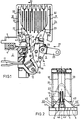
- Figure 1 shows the contact arrangement of a Po. les of a low voltage circuit breaker in a partially sectioned side view.
- FIG. 2 shows the section 11-11 in FIG. 1, the left and right parts of FIG. 2 showing different embodiments.
- the contact arrangement 1 according to FIGS. 1 and 2 comprises, in a known manner, a fixed part 2 and a movable part 3.
- An insulating block 4 serves as a support for the fixed part 2 of the contact arrangement 1, to which an upper connecting bar 5 is attached, which is also a fixed part Main contact is used and for this purpose is provided with a contact piece support 6 or a larger number of such contact piece supports.
- a fixed burn-off contact 7 is fastened close to the contact piece support 6, which is also provided with a contact piece support 10.
- the current band 12 establishes the electrically conductive connection with the movable part 3 of the contact arrangement 1, which is pivotably mounted about a hinge pin 13 arranged between the legs of the U-shaped current band 12.
- the movable part 3 comprises a carrier 14 on which the main contact lever 16, which is connected to the current band 12, is pivotably mounted about a hinge pin 15. These are provided at their upper end with contact piece supports 17 which cooperate with the fixed contact piece supports 6.
- the carrier 14 has a burn-off contact 20 which has a contact piece support 21 which interacts with the fixed contact piece support 10.
- Both the stationary part 2 and the movable part 3 of the contact arrangement 1 have an arcing horn 22 or 23 in order to convert switching arcs into an arcing chamber 24.
- FIG. 2 shows, there are two fixed contact piece supports 6 as main contacts. Accordingly, the movable part 3 of the contact arrangement 1 has two contact levers arranged next to one another with contact piece supports 17. Depending on the current that the circuit breaker should be able to handle with permissible heating, a larger number of main contacts can be provided. In order to illustrate this, two contact piece supports 6 are shown in the right part of FIG. 2, so that in this embodiment the contact arrangement has a total of four main contacts.
- the movable part of the contact arrangement 1 is connected in an articulated manner to the carrier 14 by means of a suitable type of drive device, not shown, via an insulating coupling 25 by means of a bolt 26.
- the contact arrangement 1 is closed by moving the isolating coupling 25 in the direction of the arrow 27, the contact piece supports 10 and 21 of the burn-off contacts first and then the contact piece supports 6 and 17 of the main contacts coming into contact with one another.
- the bearing pin 26 acts as a fixed pivot bearing of the carrier 14, so that pressure springs 30 arranged between the legs of the U-shaped curved current band act as contact force springs. If, on the other hand, the drive device is released and the isolating coupling 25 is thereby released, the compression springs 30 act as switch-off springs and transfer the contact arrangement into the switch-off position shown in FIG. 1.
- a switching arc occurs only at the burnout contacts, provided the current flowing through the contact arrangement does not exceed a certain level.
- the switching arc is then taken over by the arcing horns 22 and 23 and transferred to the arcing chamber 24.
- This process is favored in a known manner by guide rails 31 which, in the example shown, have a U-shaped profile and are dimensioned such that the tips of the arcing horns 22 and 23 lie between the legs 32 and 33 of the arc guide rails 31.
- each arc guide piece 40 is provided with an extension 41 which rests on the fixed connecting rail 5.
- a screw 42 is used to jointly fasten the connecting bar 5 and the arc guide piece 40 to the insulating block 4 by means of a threaded bush 43 embedded in the insulating block 4 the contact piece supports 6 reached.
- the further edges 45 and 46 act as leading edges of the partial arcs upwards in the direction of the arcing horns 22 and 23. These edges are at an acute angle to one another and are dimensioned such that they reach the arcing horn 22 beyond the contact piece support 10.
- the different embodiments shown in the left and right parts of FIG. 2 show that the size of the arc guide pieces can be easily adapted to the number of main contacts present.
- the lower edge 44 'of the arc guide piece 40' is longer, as is the edge 45 'leading to the arcing horn.
- the arc guide pieces 40 and 40 ' can be made of sheet steel with an angled portion for fastening. In the illustrated In the exemplary embodiment, however, the arc guide pieces are made of cast steel, since the parts of different thickness desired for guiding the arcs and for fastening can be produced more easily in this way. A relatively large thickness of the arc guide pieces, ie a correspondingly large mass of ferromagnetic material, can prove to be advantageous for the desired effect. Good results have been achieved, for example, in a circuit breaker for a rated current of 1600 A with two main contacts (left part of FIG. 2) in connection with two arc guiding pieces made of jet casting each weighing 60 g.
- the fixed part 2 of the contact arrangement 1 is provided with arcing elements.
- This arrangement has proven to be effective and has the advantage that the mass of the movable part 3 does not have to be increased by additional parts.
- the movable part 3 could also be provided with arc guide pieces, although it may be sufficient, in contrast to the solid arc guide pieces described, to use thinner material, e.g. made of sheet steel. In this case the magnification of the moving mass is so small that an influence on the mechanical switching process cannot be determined.
Landscapes
- Arc-Extinguishing Devices That Are Switches (AREA)
- Driving Mechanisms And Operating Circuits Of Arc-Extinguishing High-Tension Switches (AREA)
Description
- Die Erfindung betrifft eine Kontaktanordnung für Niederspannungs-Leistungsschalter mit Hauptkontakten zur Führung eines Dauerstromes und mit Abbrennkontakten zur Zündung eines Schaltlichtbogens im Eintrittsbereich einer Lichtbogenlöschkammer, sowie mit Lichtbogenhörnern zur Überführung des Schaltlichtbogens in die Lichtbogenlöschkammer, wobei wenigsten zwei Hauptkontakt-Schaltstückauflagen in einer Reihe nebeneinander angeordnet sind und im Abstand hiervon wenigstens eine Abbrennkontakt-Schaltstückauflage angeordnet ist.
- Eine Kontaktanordnung dieser Art ist beispielsweise durch die DE-A-2 218 420 bekannt geworden. Solche Kontaktanordnungen werden üblicherweise gewählt, um einen hohen Strom über längere Zeit mit möglichst geringer Erwärmung der Kontaktanordnung übertragen zu können. Im Prinzip wird dies dadurch erreicht, daß die Hauptkontakte lichtbogenfrei arbeiten und infolgedessen einem die Kontaktflächen beeinträchtigenden Abbrand nicht ausgesetzt sind. Wird eine solche Kontaktanordnung zum Abschalten geöffnet, so werden die zunächst über die Hauptkontakte fließenden Ströme auf die Abbrennkontakte kommutiert, so daß nur diese mit dem Schaltlichtbogen beaufschlagt werden.
- Es ist jedoch bekannt, daß unter bestimmten Bedingungen, insbesondere bei einer Überlastung der Kontaktanordnung durch sehr hohe Ströme, selbst dann an den Hauptkontakten Teillichtbögen auftreten können, wenn die Hauptkontakte gegenüber den Abbrennkontakten voreilend geöffnet werden. Um solche Erscheinungen ohne Gefahr für die Kontaktanordnung beherrschen zu können, ist es bekannt, die Löschbleche der zugehörigen Uchtbogenlöschkammer in der Weise verbreitert auszuführen, daß nicht nur den Abbrennkontakten, sondern auch den Hauptkontakten Eintrittskanten der Löschbleche gegenüberstehend angeordnet sind (DE-A-2 218 420). Diese Ausführung der Löschbleche erfordert es jedoch, daß die Lichtbogenlöschkammer zumindest in ihrem unmittelbar an die Kontaktanordnung angrenzenden Bereich die gleiche Breite wie die Kontaktanordnung aufweist. Bei einer Vielzahl von Abschaltvorgängen wäre jedoch dieses große Volumen der Lichtbogenlöschkammer nicht erforderlich, da nur ein an den Abbrennkontakten auftretender Lichtbogen in die Löschkammer zu überführen ist.
- Der Erfindung liegt hiervon ausgehend die Aufgabe zugrunde, eine solche Ausgestaltung der Kontaktanordnung anzugeben, die es gestattet, eine relativ schmale, d.h. im wesentlichen den Abbrennkontakten angepaßte Lichtbogenlöschkammer auch dann anwenden zu können, wenn mit einer Lichbogenbildung an den Hauptkontakten zu rechnen ist.
- Diese Aufgabe wird gemäß der Erfindung dadurch gelöst, daß in dem Raum zwischen den Hauptkontakt-Schaltstückauflagen und der Abbrennkontakt-Schaltstückauflage ein Lichtbogenleitstück aus einem ferromagnetischen Material angeordnet ist.
- Die Wirkung des Lichtbogenleitstückes beruht auf der bekannten Erscheinung, daß Lichtbögen von ferromagnetischen Teilen angezogen werden und sich auf diese Weise in eine gewünschte Richtung leiten lassen (vgl. z.B. DE-A-1 690 137). Durch die vorgeschlagenen Licht bogenleitstücke werden im Falle der Uberlastung an den Hauptkontakten auftretende Teillichtbögen angezogen und übernommen. Sie gelangen dann aufgrund bekannter Kommutierungsvorgänge beispielsweise zu dem Abbrennkontakt oder zu den Lichtbogenhörnern und vereinigen sich an diesen Teilen zu einem einheitlichen Schaltlichtbogen. Da somit nur dieser in die Lichtbogenlöschkammer zu überführen ist, genügt es, die Lichtbogenlöschkammer in ihren Abmessungen den Abbrennkontakten anzupassen. Infolge ihres geringeren Volumens ist dadurch die Lichtbogenlöschkammer gegenüber der bekannten Ausführung mit verbreiterten Löschblechen preiswerter herstellbar.
- Für die Überführung der Teillichbögen von den Hauptkontakten zu dem Abbrennkontakt hat es sich als vorteilhaft erwiesen, die Lichtbogenleitstücke mit einer etwa dreieckförmigen Gestalt auszuführen, wobei jeweils eine Seite der Dreieckform die Hauptkontakte und eine weitere Seite den Zwischenraum zwischen der Oberkante der Hauptkontakte und der Oberkante des zugehörigen Abbrennkontaktes überdeckt. Auf diese Weise werden wirksame Führungskanten für die Teillichtbögen gebildet.
- Ferner können zwei Kanten der Dreieckform so angeordnet sein, daß sie unter einem spitzen Winkel stehen, der zu dem Lichtbogenhorn des zugehörigen Abrennkontaktes führt. Auf diese Weise läßt sich erreichen, daß die Teillichtbögen erst an dem Lichtbogenhorn mit dem Hauptlichtbogen zusammentreffen und eine zusätzliche Beanspruchung der Abbrennkontakte unterbleibt.
- Die nach der Erfindung vorgesehenen Lichtbogenleitstücke können aus Stahlblech bestehende Stanz-Biegeteile sein, oder es kann sich um ferromagnetische Gußstücke handeln. Es hat sich erwiesen, daß die Masse der Lichtbogenleitstücke, d.h. bei gegebener Fläche ihre Dicke, einen Einfluß auf die erwünschte Wirkung hat. Je nach der angestrebten Wirkung kann es daher zweckmäßig sein, mehr oder weniger dicke Lichtbogenleitstücke zu verwenden. Bei der Ausführung als Gußteil erweist es sich als vorteilhaft, einen dickwandigen Teil zur Führung von Lichtbögen und einen dünnwandigen Teil zur Befestigung vorzusehen.
- Im Prinzip kann sowohl der feststehende Teil als auch der bewegliche Teil der Kontaktanordnung mit Lichtbogenleitstücken versehen werden, oder beide Teile der Kontaktanordnung können Lichtbogenleitstücke erhalten. Es hat sich gezeigt, daß eine günstige Wirkung bereits durch eine entsprechende Ausrüstung des feststehenden Teiles zu erzielen ist. Die Erfindung wird im folgenden anhand des in den Figuren dargestellten Ausführungsbeispiele näher erläutert.
- Die Figur 1 zeigt die Kontaktanordnung eines Po- . les eines Niederspannungs-Leistungsschalters in einer teilweise geschnittenen Seitenansicht.
- Die Figur 2 zeigt den Schnitt 11-11 in Figur 1, wobei der linke und der rechte Teil der Figur 2 unterschiedliche Ausführungsformen zeigen.
- Die Kontaktanordnung 1 gemäß den Figuren 1 und 2 umfaßt in bekannter Weise einen feststehenden Teil 2 und einen bewegbaren Teil 3. Als Träger des feststehenden Teiles 2 der Kontaktanordnung 1 dient ein Isolierblock 4, an dem eine obere Anschlußschiene 5 angebracht ist, die zugleich als feststehender Hauptkontakt dient und hierzu mit einer Schaltstückauflage 6 oder einer größeren Anzahl solcher Schaltstückauflagen versehen ist. Auf der Anschlußschiene 5 ist nahe bei der Schaltstückauflage 6 ein feststehender Abbrennkontakt 7 befestigt, der gleichfalls mit einer Schaltstückauflage 10 versehen ist. An der Unterseite des im Profil winkelförmigen Isolierblockes 4 ist eine weitere, gegabelt ausgeführte Anschlußschiene 11 befestigt, mit der durch eine Schraubverbindung ein biegsames Stromband 12 verbunden ist. Das Stromband 12 stellt die elektrisch leitende Verbindung mit dem beweglichen Teil 3 der Kontaktanordnung 1 her, der um einen zwischen den Schenkeln des U-förmig gebogenen Strombandes 12 angeordneten Gelenkbolzen 13 schwenkbar gelagert ist. Der bewegbare Teil 3 umfaßt einen Träger 14, an dem um einen Gelenkbolzen 15 mit dem Stromband 12 in Verbindung stehende Hauptkontakthebel 16 schwenkbar gelagert sind. Diese sind an ihrem oberen Ende mit Schaltstückauflagen 17 versehen, die mit den ortsfesten Schaltstückauflagen 6 zusammenwirken. Ferner weist der Träger 14 einen Abbrennkontakt 20 auf, der eine mit der ortsfesten Schaltstückauflage 10 zusammenwirkende Schaltstückauflage 21 besitzt. Sowohl der ortsfeste Teil 2 als auch der bewegbare Teil 3 der Kontaktanordnung 1 besitzen ein Lichtbogenhorn 22 bzw. 23, um Schaltlichtbögen in eine Lichtbogenlöschkammer 24 zu überführen.
- Wie die Figur 2 zeigt, sind zwei ortsfeste Schaltstückauflagen 6 als Hauptkontakte vorhanden. Dementsprechend weist der bewegbare Teil 3 der Kontaktanordnung 1 zwei nebeneinander angeordnete Kontakthebel mit Schaltstückauflagen 17 auf. In Abhängigkeit von dem Strom, den der Leistungsschalter mit einer zulässigen Erwärmung beherrschen soll, kann eine größere Anzahl von Hauptkontakten vorgesehen sein. Um dies zu veranschaulichen, sind im rechten Teil der Figur 2 zwei Schaltstückauflagen 6 gezeigt, so daß bei dieser Ausführung die Kontaktanordnung insgesamt vier Hauptkontakte aufweist.
- Zum Ein- und Ausschalten ist der bewegbare Teil der Kontaktanordnung 1 über eine nicht dargestellte Antriebsvorrichtung geeigneter Art über eine lsolierkoppel 25 mittels eines Bolzens 26 gelenkig mit dem Träger 14 verbunden. Ausgehend von der dargestellten Ausschaltstellung wird die Kontaktanordnung 1 durch Bewegung der lsolierkoppel 25 in Richtung des Pfeiles 27 geschlossen, wobei zunächst die Schaltstückauflagen 10 und 21 der Abbrennkontakte und anschließend die Schaltstückauflagen 6 und 17 der Hauptkontakte miteinander in Berührung treten. In der verklinkten Endstellung der Antriebsvorrichtung wirkt der Lagerbolzen 26 als ortsfestes Schwenklager des Trägers 14, so daß nun zwisehen den Schenkeln des U-förmig gebogenen Strombandes angeordnete Druckfedern 30 als Kontaktkraftfedern wirken. Wird andererseits die Antriebsvorrichtung entklinkt und hierdurch die Isolierkoppel 25 freigegeben, so wirken die Druckfedem 30 als Ausschaltfedern und überführen die Kontaktanordnung in die in der Figur 1 gezeigte Ausschaltstellung.
- Vollzieht sich die Bewegung der Teile beim Ausschalten in bekannter Weise derart, daß zunächst die Hauptkontakte und danach die Abbrennkontakte voneinander getrennt werden, so entsteht ein Schaltlichtbogen nur an den Abbrennkontakten, sofern der über die Kontaktanordnung fließende Strom eine gewisse Höhe nicht überschreitet. Der Schaltlichtbogen wird dann von den Lichtbogenhörnern 22 und 23 übernommen und in die Lichtbogenlöschkammer 24 überführt. Dieser Vorgang wird in bekannter Weise durch Leitschienen 31 begünstigt, die in dem dargestellten Beispiel ein U-förmiges Profil aufweisen und so bemessen sind, daß die Spitzen der Lichtbogenhörner 22 und 23 zwischen den Schenkeln 32 und 33 der Lichtbogenleitschienen 31 liegen. Übersteigt jedoch der fließende Strom eine bestimmte Größe, so wird der Strom nicht vollständig auf die Abbrennkontakte kommutiert mit dem Ergebnis, daß auch an den Hauptkontakten, d. h. zwischen den Schaltstückauflagen 6 und 17 Teillichtbögen auftreten. Diese werden von zusätzlichen Lichtbogenleitstücken 40 aufgenommen und gleichfalls zu den Lichtbogenhörnern geleitet. Die Lichtbogenleitstücke 40 sind symmetrisch beidseitig des feststehenden Abbrennkontaktes 7 mit der Schaltstückauflage 10 angeordnet und weisen eine etwa dreieckförmige Gestalt auf. Zur Befestigung ist jedes Lichtbogenleitstück 40 mit einem Fortsatz 41 versehen, der auf der ortsfesten Anschlußschiene 5 aufliegt. Eine Schraube 42 dient zur gemeinsamen Befestigung der Anschlußschiene 5 und des Lichtbogenleitstückes 40 an dem Isolierblock 4 mittels einer in den Isolierblock 4 eingebetteten Gewindebuchse 43. Eine ungehinderte Übernahme der Teillichtbögen von den Hauptkontakten wird durch möglichst enge Nachbarschaft zwischen der unteren Kante 44 des Lichtbogenleitstückes 40 mit den Schaltstückauflagen 6 erreicht. Die weiteren Kanten 45 und 46 wirken als Führungskanten der Teillichtbögen nach oben in Richtung zu den Lichtbogenhörnern 22 und 23. Diese Kanten stehen hierzu in einem spitzen Winkel zueinander und sind so bemessen, daß sie bis über die Schaltstückauflage 10 an das Lichtbogenhorn 22 heranreichen.
- Die in dem linken und dem rechten Teil der Figur 2 gezeigten unterschiedlichen Ausführungsformen lassen erkennen, daß die Größe der Lichtbogenleitstücke an die jeweils vorhandene Anzahl von Hauptkontakten auf einfache Weise anzupassen ist. Entsprechend der größeren Anzahl von Schaltstückauflagen 6 im rechten Teil der Figur 2 ist die Unterkante 44' des Lichtbogenleitstückes 40' länger, ebenso wie die zu dem Lichtbogenhorn führende Kante 45'.
- Die Lichtbogenleitstücke 40 bzw. 40' können aus Stahlblech mit einer zu Befestigung dienenenden Abwinklung hergestellt sein. In dem dargestellten Ausführungsbeispiel sind die Lichtbogenleitstücke jedoch aus Stahlguß hergestellt, da sich auf diese Weise die zur Führung der Lichtbögen und zur Befestigung erwünschten Teile unterschiedlicher Dicke leichter herstellen lassen. Eine verhältnismäßig große Dicke der Lichtbogenleitstücke, d.h. eine entsprechend große Masse an ferromagnetischem Werkstoff, kann sich für die angestrebte Wirkung als vorteilhaft erweisen. Gute Ergebnisse wurden beispielsweise bei einem Leistungsschalter für einen Nenn strom von 1600 A mit zwei Hauptkontakten (linker Teil der Figur 2) in Verbindung mit zwei Lichtbogenleitüken aus Strahlguß von je 60 g Gewicht erzielt.
- Wie insbensondere die Figur 1 zeigt, ist ner der feststehende Teil 2 der Kontaktanordnung 1 mit Lichtbogenlietstücken versehen. Diese Anordnung hat sich als wirksam erwiesen und besitzt den Vorteil, daß die Masse des bewegbaren Teiles 3 durch zusätzliche Teile nicht vergrößert werden muß. Jedoch könnte auch der bewegbare Teil 3 mit Lichtbogenleitstücken versehen werden, wobei es ausreichend sein kann, im Unterschied zu den beschriebenen massiven Lichtbogenleitstücken solche aus dünnerem Werkstoff, z.B. aus Stahlblech, zu verwenden. In diesem Fall ist die Vergrößerung der bewegten Masse so gering, daß ein Einfluß auf den mechanischen Schaltvorgang nicht festzustellen ist.
Claims (5)
Applications Claiming Priority (2)
| Application Number | Priority Date | Filing Date | Title |
|---|---|---|---|
| DE3539673 | 1985-11-06 | ||
| DE19853539673 DE3539673A1 (de) | 1985-11-06 | 1985-11-06 | Kontaktanordnung fuer niederspannungs-leistungsschalter mit hauptkontakten und abbrennkontakten |
Publications (2)
| Publication Number | Publication Date |
|---|---|
| EP0222684A1 EP0222684A1 (de) | 1987-05-20 |
| EP0222684B1 true EP0222684B1 (de) | 1990-01-17 |
Family
ID=6285499
Family Applications (1)
| Application Number | Title | Priority Date | Filing Date |
|---|---|---|---|
| EP86730160A Expired - Lifetime EP0222684B1 (de) | 1985-11-06 | 1986-10-16 | Kontaktanordnung für Niederspannungs-Leistungsschalter mit Hauptkontakten und Abbrennkontakten |
Country Status (4)
| Country | Link |
|---|---|
| US (1) | US4720613A (de) |
| EP (1) | EP0222684B1 (de) |
| JP (1) | JP2606798B2 (de) |
| DE (2) | DE3539673A1 (de) |
Families Citing this family (10)
| Publication number | Priority date | Publication date | Assignee | Title |
|---|---|---|---|---|
| DE8715757U1 (de) * | 1987-11-25 | 1988-02-18 | Siemens AG, 1000 Berlin und 8000 München | Niederspannungs-Leistungsschalter |
| US4926018A (en) * | 1988-09-08 | 1990-05-15 | Siemens Energy & Automation, Inc. | Moving mains arc movement loop |
| JPH0684652U (ja) * | 1993-05-11 | 1994-12-02 | 株式会社東海理化電機製作所 | スライドスイッチ |
| DE19913236C2 (de) * | 1999-03-23 | 2001-02-22 | Siemens Ag | Verfahren zur Strombegrenzung in Niederspannungsnetzen und zugehörige Anordnung |
| DE19930813A1 (de) * | 1999-06-30 | 2001-01-04 | Siemens Ag | Leistungsschalter mit Anschlußschienen für verschiedene Nennströme |
| FR2795858B1 (fr) * | 1999-07-01 | 2001-09-14 | Schneider Electric Ind Sa | Appareillage electrique de coupure dont un organe de contact est muni d'un pare etincelle |
| DE19939710A1 (de) | 1999-08-18 | 2001-02-22 | Siemens Ag | Anschlußschienen für elektrische Geräte und Apparate für verschiedene Nennströme |
| DE10250950B4 (de) * | 2002-10-25 | 2004-10-28 | Siemens Ag | Niederspannungs-Leistungsschalter |
| JP6005085B2 (ja) * | 2014-03-10 | 2016-10-12 | 三菱電機株式会社 | 開閉装置 |
| KR102833350B1 (ko) * | 2023-04-13 | 2025-07-10 | 엘에스일렉트릭(주) | 부하 개폐기 |
Family Cites Families (7)
| Publication number | Priority date | Publication date | Assignee | Title |
|---|---|---|---|---|
| DE1000486B (de) * | 1954-05-04 | 1957-01-10 | Calor Emag Elektrizitaets Ag | Hornfoermiger Schaltkontakt mit einer Einlage aus magnetischem Material |
| IT712788A (de) * | 1963-08-21 | |||
| JPS4213041Y1 (de) * | 1964-05-04 | 1967-07-25 | ||
| JPS4511130Y1 (de) * | 1965-09-07 | 1970-05-19 | ||
| DE1690137B2 (de) * | 1968-01-31 | 1973-08-30 | Siemens AG, 1000 Berlin u 8000 München | Elektrischer leistungsschalter, insbesondere niederspannungs-leistungsschalter |
| US3749867A (en) * | 1971-04-01 | 1973-07-31 | Westinghouse Electric Corp | Spaced-metallic-plate-type of arc-chute for a switch |
| US3784775A (en) * | 1972-07-27 | 1974-01-08 | Ite Imperial Corp | Arc runner between stationary contacts |
-
1985
- 1985-11-06 DE DE19853539673 patent/DE3539673A1/de not_active Withdrawn
-
1986
- 1986-10-16 DE DE8686730160T patent/DE3668394D1/de not_active Expired - Lifetime
- 1986-10-16 EP EP86730160A patent/EP0222684B1/de not_active Expired - Lifetime
- 1986-10-24 US US06/922,729 patent/US4720613A/en not_active Expired - Fee Related
- 1986-11-04 JP JP61262583A patent/JP2606798B2/ja not_active Expired - Lifetime
Also Published As
| Publication number | Publication date |
|---|---|
| US4720613A (en) | 1988-01-19 |
| JP2606798B2 (ja) | 1997-05-07 |
| EP0222684A1 (de) | 1987-05-20 |
| JPS62108418A (ja) | 1987-05-19 |
| DE3539673A1 (de) | 1987-05-07 |
| DE3668394D1 (de) | 1990-02-22 |
Similar Documents
| Publication | Publication Date | Title |
|---|---|---|
| EP0876671B1 (de) | Elektrisches schaltgerät | |
| EP1192628B1 (de) | Schaltkontaktanordnung eines niederspannungs-leistungsschalters mit hauptkontakten, zwischenkontakten und abreisskontakten | |
| DE3302884A1 (de) | Elektrischer leistungsschalter | |
| EP0222684B1 (de) | Kontaktanordnung für Niederspannungs-Leistungsschalter mit Hauptkontakten und Abbrennkontakten | |
| CH677045A5 (de) | ||
| EP0219449B1 (de) | Kontaktanordnung für Niederspannungs- Leitungsschalter mit einem biegsamen Stromband | |
| DE9320696U1 (de) | Relais zum Schalten hoher Stromstärken | |
| EP1360709A1 (de) | Schaltkontaktanordnung | |
| DE3432086A1 (de) | Kontaktanordnung mit einer die kontaktkraft vergroessernden stromabhaengigen kraft | |
| EP1423862B1 (de) | Schaltkontaktanordnung mit einer einrichtung zur verstärkung einer zwischen schaltkontakten wirkenden kontaktkraft | |
| EP1261981B1 (de) | Schaltpol für niederspannungs-schaltgeräte mit linear bewegbarem kontaktträger | |
| DE10048659A1 (de) | Schaltkontaktanordnung eines Niederspannungs-Leistungsschalter mit Kontaktkraftfedern | |
| EP1374263B1 (de) | Schaltanordnung für niederspannungs-leistungsschalter | |
| DE102019117804B4 (de) | Schalteinrichtung mit einem elektrischen Kontaktsystem | |
| EP0358287B1 (de) | Antriebsbauteil für einen mehrpoligen Niederspannungs-Leistungsschalter | |
| DE69030666T2 (de) | Ausschalter | |
| EP0632928B1 (de) | Vakuumschalter mit einer stromschleifenanordnung | |
| WO2001024207A1 (de) | Niederspannungs-leistungsschalter mit einer schaltkammer und einem bewegbaren kontaktträger | |
| DE2817668B1 (de) | Niederspannungs-Leistungsschalter mit einer Einrichtung zur Begrenzung von Kontaktabhebungen | |
| DE2019885A1 (de) | Springkontaktsatz | |
| EP0091082B1 (de) | Elektromagnetisch betätigbares Schaltgerät | |
| EP0910858B1 (de) | Schaltkontaktanordnung mit einer gelenkanordnung für einen kontakthebel | |
| DE69305147T2 (de) | Kontaktvorrichtung | |
| EP0358288B1 (de) | Kontaktanordnung für einen Leistungsschalter mit Vor- und Hauptkontakten | |
| DE2723624A1 (de) | Elektrischer schalter |
Legal Events
| Date | Code | Title | Description |
|---|---|---|---|
| PUAI | Public reference made under article 153(3) epc to a published international application that has entered the european phase |
Free format text: ORIGINAL CODE: 0009012 |
|
| AK | Designated contracting states |
Kind code of ref document: A1 Designated state(s): DE FR GB IT SE |
|
| 17P | Request for examination filed |
Effective date: 19870626 |
|
| 17Q | First examination report despatched |
Effective date: 19890116 |
|
| GRAA | (expected) grant |
Free format text: ORIGINAL CODE: 0009210 |
|
| AK | Designated contracting states |
Kind code of ref document: B1 Designated state(s): DE FR GB IT SE |
|
| REF | Corresponds to: |
Ref document number: 3668394 Country of ref document: DE Date of ref document: 19900222 |
|
| ET | Fr: translation filed | ||
| GBT | Gb: translation of ep patent filed (gb section 77(6)(a)/1977) | ||
| ITF | It: translation for a ep patent filed | ||
| PLBE | No opposition filed within time limit |
Free format text: ORIGINAL CODE: 0009261 |
|
| STAA | Information on the status of an ep patent application or granted ep patent |
Free format text: STATUS: NO OPPOSITION FILED WITHIN TIME LIMIT |
|
| 26N | No opposition filed | ||
| ITTA | It: last paid annual fee | ||
| EAL | Se: european patent in force in sweden |
Ref document number: 86730160.8 |
|
| PGFP | Annual fee paid to national office [announced via postgrant information from national office to epo] |
Ref country code: GB Payment date: 19950918 Year of fee payment: 10 |
|
| PGFP | Annual fee paid to national office [announced via postgrant information from national office to epo] |
Ref country code: SE Payment date: 19951019 Year of fee payment: 10 |
|
| PG25 | Lapsed in a contracting state [announced via postgrant information from national office to epo] |
Ref country code: GB Effective date: 19961016 |
|
| PG25 | Lapsed in a contracting state [announced via postgrant information from national office to epo] |
Ref country code: SE Effective date: 19961017 |
|
| GBPC | Gb: european patent ceased through non-payment of renewal fee |
Effective date: 19961016 |
|
| EUG | Se: european patent has lapsed |
Ref document number: 86730160.8 |
|
| PGFP | Annual fee paid to national office [announced via postgrant information from national office to epo] |
Ref country code: FR Payment date: 20031029 Year of fee payment: 18 |
|
| PGFP | Annual fee paid to national office [announced via postgrant information from national office to epo] |
Ref country code: DE Payment date: 20031217 Year of fee payment: 18 |
|
| PG25 | Lapsed in a contracting state [announced via postgrant information from national office to epo] |
Ref country code: DE Free format text: LAPSE BECAUSE OF NON-PAYMENT OF DUE FEES Effective date: 20050503 |
|
| PG25 | Lapsed in a contracting state [announced via postgrant information from national office to epo] |
Ref country code: FR Free format text: LAPSE BECAUSE OF NON-PAYMENT OF DUE FEES Effective date: 20050630 |
|
| REG | Reference to a national code |
Ref country code: FR Ref legal event code: ST |
|
| PG25 | Lapsed in a contracting state [announced via postgrant information from national office to epo] |
Ref country code: IT Free format text: LAPSE BECAUSE OF NON-PAYMENT OF DUE FEES;WARNING: LAPSES OF ITALIAN PATENTS WITH EFFECTIVE DATE BEFORE 2007 MAY HAVE OCCURRED AT ANY TIME BEFORE 2007. THE CORRECT EFFECTIVE DATE MAY BE DIFFERENT FROM THE ONE RECORDED. Effective date: 20051016 |