EP0222030B1 - Bloc de connexion pour initiateur - Google Patents
Bloc de connexion pour initiateur Download PDFInfo
- Publication number
- EP0222030B1 EP0222030B1 EP85114287A EP85114287A EP0222030B1 EP 0222030 B1 EP0222030 B1 EP 0222030B1 EP 85114287 A EP85114287 A EP 85114287A EP 85114287 A EP85114287 A EP 85114287A EP 0222030 B1 EP0222030 B1 EP 0222030B1
- Authority
- EP
- European Patent Office
- Prior art keywords
- terminals
- terminal block
- initiator
- terminal
- initiators
- Prior art date
- Legal status (The legal status is an assumption and is not a legal conclusion. Google has not performed a legal analysis and makes no representation as to the accuracy of the status listed.)
- Expired
Links
Images
Classifications
-
- H—ELECTRICITY
- H01—ELECTRIC ELEMENTS
- H01R—ELECTRICALLY-CONDUCTIVE CONNECTIONS; STRUCTURAL ASSOCIATIONS OF A PLURALITY OF MUTUALLY-INSULATED ELECTRICAL CONNECTING ELEMENTS; COUPLING DEVICES; CURRENT COLLECTORS
- H01R9/00—Structural associations of a plurality of mutually-insulated electrical connecting elements, e.g. terminal strips or terminal blocks; Terminals or binding posts mounted upon a base or in a case; Bases therefor
- H01R9/22—Bases, e.g. strip, block, panel
- H01R9/24—Terminal blocks
- H01R9/26—Clip-on terminal blocks for side-by-side rail- or strip-mounting
Definitions
- the present invention relates to an initiator terminal block with at least two three-storey terminals, for the supply-related and control-related connection of one initiator or several initiators with a supply voltage source and with a signal receiver or with several signal receivers.
- all of its switching connections are made in a single terminal of such a block for one initiator each such that the initiator in question is connected directly to the voltage source via its terminal with a corresponding number of supply lines, and it is also connected is connected by means of this terminal through control lines to the signal receiver assigned to it.
- connection points for the numerous supply and control conductors per terminal, so that even when using three-level terminals, these terminals are extremely long, since three connection points are required on both the front and the back, these connection points are to be connected to one another in an electrically conductive manner by busbars or the like.
- Establishing the connections requires a great deal of attention, since both supply conductors and circuit conductors must be connected on both terminal sides.
- the present invention is therefore based on the object of creating an initiator terminal block of the generic type, the terminals of which require very little space and at the same time form a considerably simplified connection option for the various conductors.
- the solution according to the invention is that the two lower floors of the terminals of the terminal block have only one connection point, each of which is assigned a cross connector connection, while the top floor of the terminals has two connection points, only one terminal of the terminal block with its two lower floors is connected to the supply voltage source and the supply voltage is distributed via the cross connector to the lower levels of the other terminal or terminals of the terminal block for connecting the initiator or initiators there.
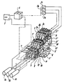
- the drawing shows an initiator terminal block according to the invention in perspective, with an illustration of the circuitry connection of the initiator terminal block with the voltage source, the initiators and the signal generators.
- the exemplary embodiment shown assumes that three initiators 1 a, 1b and 1 c are to be linked in terms of control technology to three signal receivers 2a, 2b and 2c.
- This can be, for example, three relays, each of which then closes the supply line for a contactor based on a signal from the corresponding initiator.
- the initiators 1a, 1b and 1c are supplied with the supply voltage by a voltage source, for example a rectifier 3, via the supply lines shown in dashed (+) and dash-dotted lines (-), to which the relays 2a, 2b are also connected by means of a distributor 4 and 2c.
- a voltage source for example a rectifier 3
- the supply lines shown in dashed (+) and dash-dotted lines (-) to which the relays 2a, 2b are also connected by means of a distributor 4 and 2c.
- the initiator terminal block shown now has a total of four individual terminals 5, 5a, 5b and 5c for actuating the necessary switching connections.
- the terminals 5, 5a, 5b and 5c are snapped together next to each other on a standardized mounting rail.
- the terminals 5, 5a, 5b and 5c have three levels. All terminals have only a single connection point in their two lower levels, which in the exemplary embodiment shown are screw connections 7 and 7 ' forms is. Only the top floor of the terminals has two connection points, screw connections 7 ′′ being also provided here in the exemplary embodiment shown, which are conductively connected to one another in the usual manner by a busbar 8.
- connections 7 and 7 'in the two lower floors of the terminals 5, 5a, 5b and 5c are assigned cross connector connections, for which purpose in the exemplary embodiment shown, short conductor rail pieces 9 and 9' are assigned to the screw connections, which are only slightly into the interior of the terminals protrude, so that, as the illustration of the drawing shows, there is a large free interior space in the terminals, despite their relative shortness, in which circuits and their components can also be accommodated.
- the conductor rail pieces 9 and 9 ' can also be used to connect the circuits and circuit elements which may be accommodated in the interior of the terminals, for example via solder connections here.
- the busbar pieces 9 and 9 ' also serve to connect internal cross-connectors 10 and 10' for the two lower floors, which extend over the terminals of the initiator terminal block.
- the busbar pieces 9 and 9 ' are provided with threaded holes into which screws 11 and 11', respectively, which are inserted through the cross connectors 10 and 10 ', are screwed in, the distance between the cross connectors 10, 10' and the busbar pieces 9, 9 'being determined by electrically conductive spacer sleeves 12, 12 'is bridged.
- the circuitry linking the initiators 1 a, 1 b and 1 c to the voltage source 3 is now carried out in such a way that only one terminal 5 of the initiator terminal block is connected directly to the voltage source 3 via corresponding conductors.
- the supply voltage for the three initiators 1a, 1 and 1 is then based on this one terminal 5 of the initiator terminal block via the cross connector 10,11, 12 or 10 ', 11', 12 'and the busbar pieces 9 or 9' on the other, assigned to the individual initiators, terminals 5a, 5b and 5c of the terminal block, to the two lower floors of which the initiators 1 a, 1 b and 1 c are then connected accordingly, as illustrated by the corresponding dashed conductor diagrams with corresponding arrows.
- isolating elements can be provided on the top floors of the corresponding terminals 5a, 5b, 5c of the terminal block between the two connection points, which enable the respective control circuit to be interrupted.
Landscapes
- Connections Arranged To Contact A Plurality Of Conductors (AREA)
- Dental Preparations (AREA)
- Coupling Device And Connection With Printed Circuit (AREA)
Claims (4)
Priority Applications (4)
| Application Number | Priority Date | Filing Date | Title |
|---|---|---|---|
| EP85114287A EP0222030B1 (fr) | 1985-11-09 | 1985-11-09 | Bloc de connexion pour initiateur |
| DE8585114287T DE3571177D1 (de) | 1985-11-09 | 1985-11-09 | Initiator terminal block |
| AT85114287T ATE44194T1 (de) | 1985-11-09 | 1985-11-09 | Initiatorklemmenblock. |
| US07/165,343 US4795376A (en) | 1985-11-09 | 1988-02-29 | Initiator terminal block |
Applications Claiming Priority (1)
| Application Number | Priority Date | Filing Date | Title |
|---|---|---|---|
| EP85114287A EP0222030B1 (fr) | 1985-11-09 | 1985-11-09 | Bloc de connexion pour initiateur |
Publications (2)
| Publication Number | Publication Date |
|---|---|
| EP0222030A1 EP0222030A1 (fr) | 1987-05-20 |
| EP0222030B1 true EP0222030B1 (fr) | 1989-06-21 |
Family
ID=8193874
Family Applications (1)
| Application Number | Title | Priority Date | Filing Date |
|---|---|---|---|
| EP85114287A Expired EP0222030B1 (fr) | 1985-11-09 | 1985-11-09 | Bloc de connexion pour initiateur |
Country Status (4)
| Country | Link |
|---|---|
| US (1) | US4795376A (fr) |
| EP (1) | EP0222030B1 (fr) |
| AT (1) | ATE44194T1 (fr) |
| DE (1) | DE3571177D1 (fr) |
Cited By (1)
| Publication number | Priority date | Publication date | Assignee | Title |
|---|---|---|---|---|
| EP3132502B1 (fr) | 2014-04-14 | 2021-05-19 | Weidmüller Interface GmbH & Co. KG | Bornier à blocs de jonction |
Families Citing this family (11)
| Publication number | Priority date | Publication date | Assignee | Title |
|---|---|---|---|---|
| DE3805158A1 (de) * | 1988-02-15 | 1989-08-24 | Wago Verwaltungs Gmbh | Reihenklemme zur zweileiter-stromversorgung von elektrischen oder elektronischen bauelementen, insbesondere initiatoren |
| EP0396808B1 (fr) * | 1989-05-12 | 1994-09-28 | Weidmüller Interface GmbH & Co. | Dispositif de bornes en rangée |
| JP2684897B2 (ja) * | 1991-06-24 | 1997-12-03 | 三菱電機株式会社 | 制御装置 |
| DE4324061C3 (de) * | 1993-07-17 | 2001-06-21 | Weidmueller Interface | Verteilerleiste |
| US5407367A (en) * | 1993-09-27 | 1995-04-18 | Vernitron Corporation | Barrier terminal strip assembly |
| DE4402002B4 (de) * | 1994-01-18 | 2005-10-27 | Wago Verwaltungsgesellschaft Mbh | E/A-Module/ für einen Datenbus |
| DE4438802C1 (de) * | 1994-10-31 | 1996-03-21 | Weidmueller Interface | Verteilerleisten mit Querverteilung der elektrischen Leistung (II) |
| DE4438803C1 (de) * | 1994-10-31 | 1996-03-21 | Weidmueller Interface | Verteilerleisten mit Querverteilung der elektrischen Leistung (I) |
| DE29502186U1 (de) * | 1995-02-10 | 1995-03-30 | Weidmueller Interface | Elektrische Verteileranordnung |
| DE29706125U1 (de) * | 1997-04-07 | 1997-05-22 | Weidmueller Interface | Reihenklemmenblock |
| DE102005040657A1 (de) * | 2005-08-26 | 2007-03-15 | Phoenix Contact Gmbh & Co. Kg | Elektrische Anschlussklemme |
Family Cites Families (7)
| Publication number | Priority date | Publication date | Assignee | Title |
|---|---|---|---|---|
| US2411014A (en) * | 1944-06-21 | 1946-11-12 | Us Instr Corp | Terminal block |
| GB1380533A (en) * | 1973-04-24 | 1975-01-15 | Hego Electric Gmbh | Electrical connector with insulating separator |
| DE7438186U (de) * | 1974-11-15 | 1975-07-03 | Weidmueller C Kg | Reihenklemme |
| DE7802224U1 (de) * | 1978-01-26 | 1978-06-22 | C. A. Weidmueller Kg, 4930 Detmold | Dreifachreihenklemme |
| CH646278A5 (de) * | 1978-07-29 | 1984-11-15 | Weidmueller Kg C | Reihenklemme mit schutzleiteranschluss. |
| DE3312081A1 (de) * | 1983-04-02 | 1984-10-11 | Brown, Boveri & Cie Ag, 6800 Mannheim | Zenerbarriere |
| DE3328666C2 (de) * | 1983-08-09 | 1986-08-14 | Phönix Elektrizitätsgesellschaft H. Knümann GmbH & Co KG, 4933 Blomberg | Elektrische Reihenklemme |
-
1985
- 1985-11-09 EP EP85114287A patent/EP0222030B1/fr not_active Expired
- 1985-11-09 AT AT85114287T patent/ATE44194T1/de not_active IP Right Cessation
- 1985-11-09 DE DE8585114287T patent/DE3571177D1/de not_active Expired
-
1988
- 1988-02-29 US US07/165,343 patent/US4795376A/en not_active Expired - Lifetime
Cited By (1)
| Publication number | Priority date | Publication date | Assignee | Title |
|---|---|---|---|---|
| EP3132502B1 (fr) | 2014-04-14 | 2021-05-19 | Weidmüller Interface GmbH & Co. KG | Bornier à blocs de jonction |
Also Published As
| Publication number | Publication date |
|---|---|
| US4795376A (en) | 1989-01-03 |
| EP0222030A1 (fr) | 1987-05-20 |
| ATE44194T1 (de) | 1989-07-15 |
| DE3571177D1 (de) | 1989-07-27 |
Similar Documents
| Publication | Publication Date | Title |
|---|---|---|
| EP0712267B1 (fr) | Installation de commande modulaire avec connexion sur bus secteur intégré | |
| DE4037353C1 (fr) | ||
| DE4438802C1 (de) | Verteilerleisten mit Querverteilung der elektrischen Leistung (II) | |
| EP0123822B1 (fr) | Connecteur transversal pour bornes alignées | |
| EP1022809B1 (fr) | Appareil électrique | |
| EP0726622B1 (fr) | Dispositif de distribution électrique | |
| DE2810514A1 (de) | Steckverbinder mit stoerschutz | |
| EP0222030B1 (fr) | Bloc de connexion pour initiateur | |
| EP0491260B1 (fr) | Dispositif de câblage | |
| DE19902745B4 (de) | Elektrisches Gerät | |
| CH629059A5 (de) | Mit anschlussorganen fuer anschlussdraehte versehene elektrische anschlussplatte. | |
| WO2015158505A1 (fr) | Bornier à blocs de jonction | |
| DE2927219A1 (de) | Schaltmatrix fuer die durchschaltung von breitbandigen hf-signalen | |
| DE3943752C2 (de) | Pneumatische oder hydraulische Ventileinheit | |
| EP0634813A2 (fr) | Bloc de distribution | |
| EP0739060A2 (fr) | Connecteur à broche | |
| DE2814018A1 (de) | Anschlussverteiler mit einer vielzahl von den abisolierfreien anschluss elektrischer leiter gestattenden klemmelementen | |
| DE8021913U1 (de) | Bausatz für eine Kabelverbindungsstelle mit Überspannungsschutz zum Einbau in Verbindungsmuffen | |
| DE2907207A1 (de) | Umschaltsteckverbindung | |
| EP0794592B1 (fr) | Distributeur en forme d'un peigne avec une borne de connexion | |
| DE19524850C2 (de) | Elektrische Anschlußklemme für Leiterplatten | |
| DE2340773A1 (de) | Uebergabesteckverbindung | |
| LU500973B1 (de) | Steckeinrichtung und Bausatz mit einer Steckeinrichtung | |
| DE2719269A1 (de) | Als gemeinsame betriebserde fuer die erdtasten mehrerer amtsberechtigter nebenstellen ausgebildete rangierleiste | |
| EP0746064B1 (fr) | Plaque à bornes pour des plaquettes de circuits |
Legal Events
| Date | Code | Title | Description |
|---|---|---|---|
| PUAI | Public reference made under article 153(3) epc to a published international application that has entered the european phase |
Free format text: ORIGINAL CODE: 0009012 |
|
| AK | Designated contracting states |
Kind code of ref document: A1 Designated state(s): AT CH DE FR GB IT LI NL |
|
| 17P | Request for examination filed |
Effective date: 19870613 |
|
| 17Q | First examination report despatched |
Effective date: 19881115 |
|
| ITF | It: translation for a ep patent filed |
Owner name: STUDIO INGG. FISCHETTI & WEBER |
|
| GRAA | (expected) grant |
Free format text: ORIGINAL CODE: 0009210 |
|
| AK | Designated contracting states |
Kind code of ref document: B1 Designated state(s): AT CH DE FR GB IT LI NL |
|
| REF | Corresponds to: |
Ref document number: 44194 Country of ref document: AT Date of ref document: 19890715 Kind code of ref document: T |
|
| GBT | Gb: translation of ep patent filed (gb section 77(6)(a)/1977) | ||
| REF | Corresponds to: |
Ref document number: 3571177 Country of ref document: DE Date of ref document: 19890727 |
|
| ET | Fr: translation filed | ||
| PLBE | No opposition filed within time limit |
Free format text: ORIGINAL CODE: 0009261 |
|
| STAA | Information on the status of an ep patent application or granted ep patent |
Free format text: STATUS: NO OPPOSITION FILED WITHIN TIME LIMIT |
|
| 26N | No opposition filed | ||
| ITTA | It: last paid annual fee | ||
| REG | Reference to a national code |
Ref country code: FR Ref legal event code: CD |
|
| PGFP | Annual fee paid to national office [announced via postgrant information from national office to epo] |
Ref country code: NL Payment date: 19961128 Year of fee payment: 12 |
|
| PG25 | Lapsed in a contracting state [announced via postgrant information from national office to epo] |
Ref country code: NL Free format text: LAPSE BECAUSE OF NON-PAYMENT OF DUE FEES Effective date: 19980601 |
|
| NLV4 | Nl: lapsed or anulled due to non-payment of the annual fee |
Effective date: 19980601 |
|
| REG | Reference to a national code |
Ref country code: GB Ref legal event code: IF02 |
|
| PGFP | Annual fee paid to national office [announced via postgrant information from national office to epo] |
Ref country code: GB Payment date: 20041102 Year of fee payment: 20 |
|
| PGFP | Annual fee paid to national office [announced via postgrant information from national office to epo] |
Ref country code: DE Payment date: 20041105 Year of fee payment: 20 |
|
| PGFP | Annual fee paid to national office [announced via postgrant information from national office to epo] |
Ref country code: CH Payment date: 20041109 Year of fee payment: 20 |
|
| PGFP | Annual fee paid to national office [announced via postgrant information from national office to epo] |
Ref country code: AT Payment date: 20041110 Year of fee payment: 20 |
|
| PGFP | Annual fee paid to national office [announced via postgrant information from national office to epo] |
Ref country code: FR Payment date: 20041112 Year of fee payment: 20 |
|
| PG25 | Lapsed in a contracting state [announced via postgrant information from national office to epo] |
Ref country code: GB Free format text: LAPSE BECAUSE OF EXPIRATION OF PROTECTION Effective date: 20051108 |
|
| REG | Reference to a national code |
Ref country code: GB Ref legal event code: PE20 |
|
| REG | Reference to a national code |
Ref country code: CH Ref legal event code: PL |