EP0221259A1 - Brennervorrichtung - Google Patents
Brennervorrichtung Download PDFInfo
- Publication number
- EP0221259A1 EP0221259A1 EP86110928A EP86110928A EP0221259A1 EP 0221259 A1 EP0221259 A1 EP 0221259A1 EP 86110928 A EP86110928 A EP 86110928A EP 86110928 A EP86110928 A EP 86110928A EP 0221259 A1 EP0221259 A1 EP 0221259A1
- Authority
- EP
- European Patent Office
- Prior art keywords
- burner
- nozzle
- screwed
- valve
- burner body
- Prior art date
- Legal status (The legal status is an assumption and is not a legal conclusion. Google has not performed a legal analysis and makes no representation as to the accuracy of the status listed.)
- Granted
Links
- WABPQHHGFIMREM-UHFFFAOYSA-N lead(0) Chemical compound [Pb] WABPQHHGFIMREM-UHFFFAOYSA-N 0.000 claims description 9
- 238000002347 injection Methods 0.000 claims description 5
- 239000007924 injection Substances 0.000 claims description 5
- 239000007921 spray Substances 0.000 claims description 4
- 230000003247 decreasing effect Effects 0.000 claims 1
- 238000010276 construction Methods 0.000 abstract description 4
- 230000007547 defect Effects 0.000 description 2
- 239000002184 metal Substances 0.000 description 2
- 230000002265 prevention Effects 0.000 description 2
- 239000000919 ceramic Substances 0.000 description 1
- 238000002844 melting Methods 0.000 description 1
- 230000008018 melting Effects 0.000 description 1
- 238000012856 packing Methods 0.000 description 1
- 238000003466 welding Methods 0.000 description 1
Images


Classifications
-
- F—MECHANICAL ENGINEERING; LIGHTING; HEATING; WEAPONS; BLASTING
- F23—COMBUSTION APPARATUS; COMBUSTION PROCESSES
- F23Q—IGNITION; EXTINGUISHING-DEVICES
- F23Q3/00—Igniters using electrically-produced sparks
- F23Q3/002—Igniters using electrically-produced sparks using piezoelectric elements
-
- F—MECHANICAL ENGINEERING; LIGHTING; HEATING; WEAPONS; BLASTING
- F23—COMBUSTION APPARATUS; COMBUSTION PROCESSES
- F23D—BURNERS
- F23D14/00—Burners for combustion of a gas, e.g. of a gas stored under pressure as a liquid
- F23D14/28—Burners for combustion of a gas, e.g. of a gas stored under pressure as a liquid in association with a gaseous fuel source, e.g. acetylene generator, or a container for liquefied gas
-
- F—MECHANICAL ENGINEERING; LIGHTING; HEATING; WEAPONS; BLASTING
- F16—ENGINEERING ELEMENTS AND UNITS; GENERAL MEASURES FOR PRODUCING AND MAINTAINING EFFECTIVE FUNCTIONING OF MACHINES OR INSTALLATIONS; THERMAL INSULATION IN GENERAL
- F16B—DEVICES FOR FASTENING OR SECURING CONSTRUCTIONAL ELEMENTS OR MACHINE PARTS TOGETHER, e.g. NAILS, BOLTS, CIRCLIPS, CLAMPS, CLIPS OR WEDGES; JOINTS OR JOINTING
- F16B2200/00—Constructional details of connections not covered for in other groups of this subclass
- F16B2200/69—Redundant disconnection blocking means
-
- Y—GENERAL TAGGING OF NEW TECHNOLOGICAL DEVELOPMENTS; GENERAL TAGGING OF CROSS-SECTIONAL TECHNOLOGIES SPANNING OVER SEVERAL SECTIONS OF THE IPC; TECHNICAL SUBJECTS COVERED BY FORMER USPC CROSS-REFERENCE ART COLLECTIONS [XRACs] AND DIGESTS
- Y10—TECHNICAL SUBJECTS COVERED BY FORMER USPC
- Y10S—TECHNICAL SUBJECTS COVERED BY FORMER USPC CROSS-REFERENCE ART COLLECTIONS [XRACs] AND DIGESTS
- Y10S251/00—Valves and valve actuation
- Y10S251/903—Needle valves
Definitions
- This invention relates to a conpact type burner device for use of welding, melting cut, and various metalworks.
- This type of conventional burner device comprises a connecting member which pinches the top periphery of a liquefied gas bomb at the lower side of a burner body.
- This connecting member has such defect as not being applicable to a commercial portable liquefied gas bomb though it is effective to a particular liquefied gas bomb.
- the object of this invention is to provide a burner device wherein said burner is provided with two connecting means so that a liquefied gas bomb having a different top construction may be used and further in some case a liquefied gas bomb is connected twice with two connected means so that the combination of the burner device with said liquefied gas bomb may be more ensured.
- the invention comprises a burner body having a nozzle device at the front portion and a valve one at the rear respectively, and further having an integrally formed cylindrical connecting portion at the lower side thereof; a connecting member installed in said connecting portion whose lower portion protruded from the connecting portion forms an intake opening, in said intake opening an injection stem being protruded therein downwardly; a cap-shaped holder inserted into the periphery of said intake opening and having protrusions for latching at inner side of the circumferential wall; and a rotative holder clamping member screwed to the outer circumference of said connecting portion at the outside of said holder.
- this invention is to provide a burner device having a new construction which enables to ignite a gas by an igniter provided to the burner device in a state of being holded.
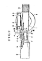
- the igniter used for this invention is a piezoelectric ignition device which is contained in a casing formed at the side of the burner body, said piezoelectric ignition device being constituted to discharge in a burner provided at the top end portion of the nozzle device, thereby igniting the discharged gas.
- the numeral 1 is a burner device body, at the front and the rear of said burner device body a nozzle device 2 and a valve device 3 for controlling a quantity of flowing gas being screwed thereto respectively. Further, a cylindrical connecting portion 4 is integrally formed at the lower side thereof.
- Screws are provided to the inner and the outer sides of the connecting portion 4, at the inner portion of said connecting portion 4 and the periphery of the same a connecting member 5 and a cap-shaped clamping member 6 being rotatively screwed respectively.
- the connecting member 5 is a hollow body, the lower portion thereof protruding from the outer end of the connecting portion 4 to form an intake opening 7 having a larger diameter than that of the connecting portion 4.
- a screw 8 is provided at the inner side of said intake opening 7.
- the inner diameter of the intake opening 7 is formed slightly larger than the outer diameter of a closed portion 102 of the bomb protruded at the mid-position of a mountain cap 101 of the bomb 100, and an injection stem 9 for opening the valve of the closed portion is protruded downwardly at the mid-position of the inner portion by being engaged with a sleeve 10.
- the periphery of the lower end of the intake opening 7 is formed to be a flange 11 and the mid-portion 12a of the cap-shaped holder 12 is rotatively fitted downwardly between the flange 11 and the lower end of the connecting member 5.
- the mid-portion 12a has a block shape in sectional area and its diameter is formed to be approximately equal to the inner diameter of the top periphery 103 of the mountain cap 101.
- a protrusion 13 engaged with the lower portion of the outer edge of the top periphery 103 is formed integrally.
- the above clamping member 6 has a size capable of containing the holder 12 therein and is provided with a taper surface 6a which urges the protrusion 13 to the periphery edge 103 of the top portion by pressing the holder 12 to the inner side of the lower edge.
- the numeral 14 is a stopping screw and 15 is a packing in the intake opening.
- the above nozzle device 2 is provided with a nozzle base pipe 21 screwed to the burner body 1 at the rear end thereof and a nozzle tube 22 connected with the top end portion of the nozzle base pipe 21.
- a spray nozzle 24 is provided together with a filter 23 in the rear of the nozzle pipe 21 interiorly, while an air intake hole 25 is bored at the wall portion of the spray opening side.
- a cylindrical nozzle head 26 which forms a burner is equipped.
- a plurality of spline grooves are formed, and the rear end portion of the nozzle head 26 is inserted integrally into the opening of the nozzle tube at the top end thereof and together with it a part of a flow passage 28 is allowed to divide around the nozzle head so that the main passage 28a and a sub-passage 28 may be separately formed.
- ring members 29, 30 are inserted into the opening end and the periphery of the nozzle head 27 respectively.
- the ring member 29 is in a fixed state and serves as an electrode and the ring member 30 is movable and operates as a resistant body of the gas flow.
- an insulating cylinder 31 which'serves as an electrode stand and surrounds the sub-passage 28b is secured.
- the insulating cylinder 31 is formed with ceramic and have a step portion and a groove into which a whirl-stop at the inside of the burner cover is inserted, at the outer side thereof. Further, the burner cover 33 protrudes a discharge electrode 32 which serves as a latching member into the inner side is engaged with said step portion.
- the burner cover 33 is fixed with said discharge electrode 32 and a nut 34 in the rear portion, and connected with a lead wire 37 of a piezoelectric ignition device 36 provided at the side of the body 1 (See Fig. 2).
- connection with the lead wire 37 can be easily performed by inserting the top end portion of the lead wire 37 into a clearance formed between the insulating cylinder 31 and the burner cover 33, and contacting the top end portion of the lead wire to the burner cover 35.
- Fig. 5 presents a case wherein the burner cover is formed with the insulating cylinder 31 described above, at the rear end portion of said insulating cylinder 31 a dent 31a being formed coaxially. Further, a hole 31c is bored extending over the dent 31a and an opening 31b in front of the burner at the top end of the cylinder 31.
- a metal wire 32a which becomes the electrode 32 is inserted into said dent 31a and said hole 31c, and the top end portion of said lead wire 37 is inserted into the inner portion of the dent 31a toward the metal wire 32a.
- the piezoelectric ignition device 36 comprises a fixed member 38 which contains a piezoelectric element and a spring for impact therein and a removable member 39 inserted into said fixed member and always suppressed outwardly by the spring for impact as simillar to that used for gas lighter or the like, said electonic ignition device being housed in a casing 40 integrally formed at the side of the burner body 1.
- a housing groove 42 of said lead wire 37 is formed at the inside of an operating device 41 which slides along the inside of the casing, and on the surface a groove 44 which guides a screw vis 43 for prevention of sliding off screwed in the groove 44 from the burner body side is provided along the moving direction.
- Fig. 6 shows a case wherein the piezoelectric ignition device 36 is contained in the casing 40 at the side of the burner body 1 with its back toward the casing.
- the operation device 41 since the operation device 41 is protrudingly positioned from the rear end of the casing 40, the groove to contain said lead wire at the inside of the operation device becomes unnecessary. Further, since the end surface of the operation device 41 contacts with the inner end face of a valve operation device described hereafter, a screw vis for prevention of sliding off and its guide groove discribed above become unnecessary.
- the above valve device 3 is constituted of a cylinder 45 screwed into the rear portion in the burner body 1 and a valve operating device 48 which covers the needle valve 46 inserted into the cylinder 45 and a stopper member 47 integrally formed with the needle valve 46 and screwed to the rear end of the cylinder 45.
- the inner portion of the top end of said cylinder 45 is formed to be a valve seat 50 which pass through the passage 49 on the body side and the filter side described above and the top end 46a of said needle valve 46 in the cylinder screwed with the valve seat 50 rotatively is inserted therein.
- the above intake opening 7 is inserted into the inner side of top periphery edge 103 together with the holder mid-portion 12a to rotate the clamping member 6 downwardly.
- the circumferential side wall 12a of the holder 12 is pressed to the top periphery edge 103, whereby the protrusion 13 is inserted into the lower side of the periphery edge.
- the holder 12 is connected with the clamping member 6 after inserting the screw 8 positioned at the inner side of the intake opening 7 into the closed portion 102 of the bomb by pivoting the screw.
- the closed portion 102 of the bomb is pushed open by the injection stem 9 and the liquefied gas is sprayed from the inside of the connecting member 5 to the passage 28 in the nozzle pipe 21 by an injection nozzle through the main body passage 47 - valve seat 50 - filter 23. And after intaking the air, it flows out to the outward through the main passage 28a and the sub-passage 28b.
- the burner device is constituted so as to be able to connect to the liquefied gas bomb with the intake opening for connecting member internalized in the connecting.portion at the lower side of the burner body, the holder fitted at the intake opening and the clamping member rotatively screwed with around the outer circumference of the connecting portion, the liquefied gas bomb can be surely connected by either one of them. Further, in some case, since the bomb can be connected by both, this invention has such advantage that a commercial gas bomb is available for the burner device.
- the ignition by discharge is performed by a temporary ignition to a gas flow from the sub-passage having a small quantity of gas flow and then ignited to a gas flow from the main passage having a large quantity of gas flow, the discharge can be performed always surely even if the energy is small. Further, the discharge is performed at the top end or the inside of the insulating cylinder in construction, there is no peril of the electric shock by discharge.
Applications Claiming Priority (2)
| Application Number | Priority Date | Filing Date | Title |
|---|---|---|---|
| JP1985123630U JPS6234623U (de) | 1985-08-12 | 1985-08-12 | |
| JP123630/85U | 1985-08-12 |
Publications (2)
| Publication Number | Publication Date |
|---|---|
| EP0221259A1 true EP0221259A1 (de) | 1987-05-13 |
| EP0221259B1 EP0221259B1 (de) | 1989-09-27 |
Family
ID=14865341
Family Applications (1)
| Application Number | Title | Priority Date | Filing Date |
|---|---|---|---|
| EP86110928A Expired EP0221259B1 (de) | 1985-08-12 | 1986-08-07 | Brennervorrichtung |
Country Status (9)
| Country | Link |
|---|---|
| US (2) | US4804324A (de) |
| EP (1) | EP0221259B1 (de) |
| JP (1) | JPS6234623U (de) |
| KR (1) | KR950007388B1 (de) |
| CN (1) | CN1014356B (de) |
| CA (1) | CA1275907C (de) |
| DE (1) | DE3665923D1 (de) |
| HK (1) | HK4091A (de) |
| SG (1) | SG99090G (de) |
Cited By (2)
| Publication number | Priority date | Publication date | Assignee | Title |
|---|---|---|---|---|
| EP0272540A2 (de) * | 1986-12-23 | 1988-06-29 | Rothenberger Werkzeuge-Maschinen GmbH | Aufsatzbrenner mit einem Injektorsystem für Flüssiggasbehälter |
| EP0771996A3 (de) * | 1995-11-02 | 1998-03-18 | Rothenberger Werkzeuge AG | Kupplungsstück für die Verbindung von Kleingasflaschen mit Brennern |
Families Citing this family (26)
| Publication number | Priority date | Publication date | Assignee | Title |
|---|---|---|---|---|
| US5071342A (en) * | 1985-08-12 | 1991-12-10 | Prince Industrial Development Company, Ltd. | Burner device |
| US4946384A (en) * | 1988-10-07 | 1990-08-07 | London Paul W | Gas pilot-igniter for burners |
| CA2010074C (en) * | 1989-03-29 | 2001-02-13 | Gilbert Roland Farnham | Valve assembly |
| US5062791A (en) * | 1991-04-01 | 1991-11-05 | Liou Charg Shing | Gas blowtorch |
| US5286189A (en) * | 1993-02-16 | 1994-02-15 | Goss Charles T | Detachable ignitor tip for a burner assembly |
| US5466149A (en) * | 1995-02-02 | 1995-11-14 | Tsai; Chin-Lin | Heating torch |
| US5564918A (en) * | 1995-06-06 | 1996-10-15 | Lin; Arlo H. T. | Gas torch |
| US5639062A (en) * | 1995-07-25 | 1997-06-17 | Outboard Marine Corporation | Modified heel valve construction |
| US5899229A (en) * | 1996-07-25 | 1999-05-04 | Cooper Industries, Inc. | Torch valve assembly |
| US5816794A (en) * | 1997-03-20 | 1998-10-06 | Tsai; Chin-Lin | Jet type gas burning device |
| US5826618A (en) * | 1997-05-16 | 1998-10-27 | Cooper Industries, Inc. | Bonded elastomer seal valve assembly |
| US5741128A (en) * | 1997-08-21 | 1998-04-21 | Tsai; Chin-Lin | Hand gas torch |
| US6065959A (en) * | 1999-03-29 | 2000-05-23 | Tsai; Chin-Lin | Handy gas torch |
| US6063329A (en) * | 1999-04-07 | 2000-05-16 | Tsai; Chin-Lin | Mini welding/soldering torch |
| US6902708B1 (en) * | 2000-04-25 | 2005-06-07 | Air Liquide America Corporation | Method and apparatus for making carbon black |
| ES1059642Y (es) * | 2005-02-10 | 2005-09-01 | Fagor S Coop | Valvula rotatoria montada en un aparato de coccion multi-gas |
| DE102005015520A1 (de) * | 2005-04-04 | 2006-11-09 | Superfeuer Gmbh | Sprühflasche |
| RU2278328C1 (ru) * | 2005-05-13 | 2006-06-20 | Ооо "Плазариум" | Горелка |
| JP5469853B2 (ja) * | 2008-11-25 | 2014-04-16 | スタイル株式会社 | 圧電点火式ガスバーナ |
| ES1069849Y (es) | 2008-12-19 | 2009-09-14 | Coprecitec Sl | "valvula de regulacion para un aparato de coccion a gas" |
| TW201037236A (en) * | 2009-04-08 | 2010-10-16 | Pro Iroda Ind Inc | Gas torch |
| CN104214796B (zh) * | 2013-06-05 | 2016-08-17 | 航天长征化学工程股份有限公司 | 电点火装置 |
| CN204460666U (zh) * | 2013-09-08 | 2015-07-08 | 张松枢 | 一种用火机燃具加热的饮水瓶 |
| TWI537528B (zh) | 2015-03-05 | 2016-06-11 | Able to replace the barrel of the spray gun gun head | |
| TWI670449B (zh) * | 2018-11-13 | 2019-09-01 | 愛烙達股份有限公司 | 具有環狀流量撥轉環之噴火槍 |
| CN114321974B (zh) * | 2021-11-30 | 2023-06-27 | 北京航天计量测试技术研究所 | 一种适用于高压环境的隔爆型点火枪 |
Citations (3)
| Publication number | Priority date | Publication date | Assignee | Title |
|---|---|---|---|---|
| DE2824661A1 (de) * | 1978-06-05 | 1979-12-06 | Ronson Gmbh | Verbindungsstueck fuer einen gasbrenner |
| DE2905021A1 (de) * | 1979-02-09 | 1980-08-14 | Wingaersheek | Gasbrenner, insbesondere schweissbrenner |
| US4315732A (en) * | 1979-12-26 | 1982-02-16 | Jjnr Corporation | Welding apparatus |
Family Cites Families (23)
| Publication number | Priority date | Publication date | Assignee | Title |
|---|---|---|---|---|
| US2836232A (en) * | 1958-05-27 | Hand igniters for gas burners | ||
| US1182288A (en) * | 1915-11-18 | 1916-05-09 | Herbert Hooper | Adjustable ferrule for rake-handles and the like. |
| US2096945A (en) * | 1932-02-15 | 1937-10-26 | Powderco Inc | Burner |
| US2862993A (en) * | 1953-08-31 | 1958-12-02 | Amp Inc | Electric cable shield termination |
| US2942897A (en) * | 1957-12-10 | 1960-06-28 | Eon Corp | Fastening device |
| US3431058A (en) * | 1962-03-30 | 1969-03-04 | Clevite Corp | Piezoelectrically ignited gas torch |
| DE1282376B (de) * | 1962-12-04 | 1968-11-07 | Basf Ag | Gasflaschenventil fuer Hochdruckgasflaschen, insbesondere fuer korrodierende Stoffe |
| US3301306A (en) * | 1964-03-23 | 1967-01-31 | Turner Corp | Combination pencil type and heavy duty burner |
| FR1597775A (de) * | 1968-11-29 | 1970-06-29 | ||
| JPS4831211A (de) * | 1971-08-25 | 1973-04-24 | ||
| DE2208776A1 (de) * | 1972-02-24 | 1973-09-06 | Gewerk Schalker Eisenhuette | Brennvorrichtung zur verbrennung industrieller abgase |
| GB1456632A (en) * | 1972-09-08 | 1976-11-24 | Chrysler Uk | Gas torch for soldering |
| FR2269683A1 (en) * | 1974-05-02 | 1975-11-28 | Sidemat | Method of lighting barbecue wood or charcoal - uses flame produced by gas partially in liquid phase |
| US3994674A (en) * | 1975-03-14 | 1976-11-30 | Western Industries, Inc. | Detachable burner assembly for gas-burning torch |
| US4224019A (en) * | 1978-02-27 | 1980-09-23 | Westinghouse Electric Corp. | Power burner for compact furnace |
| DE2824548A1 (de) * | 1978-06-05 | 1979-12-06 | Ronson Gmbh | Schutzbuegel fuer einen gasbrenner |
| JPS6327463Y2 (de) * | 1980-09-16 | 1988-07-25 | ||
| US4601310A (en) * | 1982-12-23 | 1986-07-22 | Edwin Phillips | Quick turn metering valve |
| US4538984A (en) * | 1983-06-08 | 1985-09-03 | Katsuyuki Nakagawa | Handy torch |
| US4526532A (en) * | 1983-08-15 | 1985-07-02 | Newell Companies, Inc. | Self-igniting torch |
| CA1206862A (en) * | 1984-02-10 | 1986-07-02 | Joseph J. Mccallion | Burner attachment for aerosol container |
| JPS6118339U (ja) * | 1984-07-07 | 1986-02-03 | プリンス開発興業株式会社 | バ−ナ−装置 |
| US4601131A (en) * | 1984-11-02 | 1986-07-22 | Roland Ozols | Counterbalance spring means |
-
1985
- 1985-08-12 JP JP1985123630U patent/JPS6234623U/ja active Pending
-
1986
- 1986-08-07 DE DE8686110928T patent/DE3665923D1/de not_active Expired
- 1986-08-07 EP EP86110928A patent/EP0221259B1/de not_active Expired
- 1986-08-08 US US06/894,797 patent/US4804324A/en not_active Expired - Lifetime
- 1986-08-11 KR KR1019860006595A patent/KR950007388B1/ko not_active IP Right Cessation
- 1986-08-11 CA CA000515662A patent/CA1275907C/en not_active Expired - Lifetime
- 1986-08-12 CN CN86104997A patent/CN1014356B/zh not_active Expired
-
1988
- 1988-11-16 US US07/272,102 patent/US4938686A/en not_active Expired - Lifetime
-
1990
- 1990-12-11 SG SG990/90A patent/SG99090G/en unknown
-
1991
- 1991-01-10 HK HK40/91A patent/HK4091A/xx not_active IP Right Cessation
Patent Citations (3)
| Publication number | Priority date | Publication date | Assignee | Title |
|---|---|---|---|---|
| DE2824661A1 (de) * | 1978-06-05 | 1979-12-06 | Ronson Gmbh | Verbindungsstueck fuer einen gasbrenner |
| DE2905021A1 (de) * | 1979-02-09 | 1980-08-14 | Wingaersheek | Gasbrenner, insbesondere schweissbrenner |
| US4315732A (en) * | 1979-12-26 | 1982-02-16 | Jjnr Corporation | Welding apparatus |
Cited By (3)
| Publication number | Priority date | Publication date | Assignee | Title |
|---|---|---|---|---|
| EP0272540A2 (de) * | 1986-12-23 | 1988-06-29 | Rothenberger Werkzeuge-Maschinen GmbH | Aufsatzbrenner mit einem Injektorsystem für Flüssiggasbehälter |
| EP0272540A3 (en) * | 1986-12-23 | 1989-03-29 | Rothenberger Werkzeuge-Maschinen Gmbh | Burner with an injector system for a liquefied-gas container |
| EP0771996A3 (de) * | 1995-11-02 | 1998-03-18 | Rothenberger Werkzeuge AG | Kupplungsstück für die Verbindung von Kleingasflaschen mit Brennern |
Also Published As
| Publication number | Publication date |
|---|---|
| SG99090G (en) | 1991-02-14 |
| US4938686A (en) | 1990-07-03 |
| KR950007388B1 (ko) | 1995-07-10 |
| EP0221259B1 (de) | 1989-09-27 |
| DE3665923D1 (en) | 1989-11-02 |
| HK4091A (en) | 1991-01-18 |
| CA1275907C (en) | 1990-11-06 |
| CN86104997A (zh) | 1987-04-01 |
| CN1014356B (zh) | 1991-10-16 |
| JPS6234623U (de) | 1987-02-28 |
| KR870002419A (ko) | 1987-03-31 |
| US4804324A (en) | 1989-02-14 |
Similar Documents
| Publication | Publication Date | Title |
|---|---|---|
| EP0221259A1 (de) | Brennervorrichtung | |
| EP0515693B1 (de) | Zündanlage | |
| US3200295A (en) | Manually operable piezoelectric lighters | |
| EP0167981B1 (de) | Brennervorrichtung | |
| US4273528A (en) | Gas lighter | |
| JPH0547951Y2 (de) | ||
| US4403946A (en) | Igniter utilizing piezo-electric element | |
| US5071342A (en) | Burner device | |
| EP0259745B1 (de) | Stabförmiges und piezoelektrisches Gasfeuerzeug | |
| JPS6049813B2 (ja) | 火口 | |
| US4395227A (en) | Flame thrower attachment | |
| EP0703409B1 (de) | Flüssiggasverbrennungsvorrichtung | |
| JPS6049814B2 (ja) | 火口 | |
| US4430060A (en) | Gas lighter | |
| JPH0512583Y2 (de) | ||
| US4098309A (en) | Fuel container with filling valve | |
| JP3916110B2 (ja) | 圧電式着火用トーチ | |
| JPS6214057B2 (de) | ||
| JPS6014261B2 (ja) | 火口 | |
| EP0305025A1 (de) | Brennerdüse für Gasfeuerzeug | |
| JPS61204162U (de) | ||
| KR19990053255A (ko) | 가스점화기의 착화방법 | |
| KR800001649Y1 (ko) | 석유연소기용 점화구 | |
| KR880001382Y1 (ko) | 가스 기구의 간접 점화장치 고정구 | |
| JPS62719A (ja) | 火口 |
Legal Events
| Date | Code | Title | Description |
|---|---|---|---|
| PUAI | Public reference made under article 153(3) epc to a published international application that has entered the european phase |
Free format text: ORIGINAL CODE: 0009012 |
|
| AK | Designated contracting states |
Kind code of ref document: A1 Designated state(s): DE FR GB IT NL |
|
| 17P | Request for examination filed |
Effective date: 19870911 |
|
| 17Q | First examination report despatched |
Effective date: 19880513 |
|
| GRAA | (expected) grant |
Free format text: ORIGINAL CODE: 0009210 |
|
| AK | Designated contracting states |
Kind code of ref document: B1 Designated state(s): DE FR GB IT NL |
|
| REF | Corresponds to: |
Ref document number: 3665923 Country of ref document: DE Date of ref document: 19891102 |
|
| ITF | It: translation for a ep patent filed |
Owner name: MODIANO & ASSOCIATI S.R.L. |
|
| ET | Fr: translation filed | ||
| PLBE | No opposition filed within time limit |
Free format text: ORIGINAL CODE: 0009261 |
|
| STAA | Information on the status of an ep patent application or granted ep patent |
Free format text: STATUS: NO OPPOSITION FILED WITHIN TIME LIMIT |
|
| 26N | No opposition filed | ||
| ITTA | It: last paid annual fee | ||
| PGFP | Annual fee paid to national office [announced via postgrant information from national office to epo] |
Ref country code: DE Payment date: 20000726 Year of fee payment: 15 |
|
| PGFP | Annual fee paid to national office [announced via postgrant information from national office to epo] |
Ref country code: GB Payment date: 20000727 Year of fee payment: 15 |
|
| PGFP | Annual fee paid to national office [announced via postgrant information from national office to epo] |
Ref country code: FR Payment date: 20000817 Year of fee payment: 15 |
|
| PGFP | Annual fee paid to national office [announced via postgrant information from national office to epo] |
Ref country code: NL Payment date: 20000824 Year of fee payment: 15 |
|
| PG25 | Lapsed in a contracting state [announced via postgrant information from national office to epo] |
Ref country code: GB Free format text: LAPSE BECAUSE OF NON-PAYMENT OF DUE FEES Effective date: 20010807 |
|
| PG25 | Lapsed in a contracting state [announced via postgrant information from national office to epo] |
Ref country code: NL Free format text: LAPSE BECAUSE OF NON-PAYMENT OF DUE FEES Effective date: 20020301 |
|
| GBPC | Gb: european patent ceased through non-payment of renewal fee |
Effective date: 20010807 |
|
| PG25 | Lapsed in a contracting state [announced via postgrant information from national office to epo] |
Ref country code: FR Free format text: LAPSE BECAUSE OF NON-PAYMENT OF DUE FEES Effective date: 20020430 |
|
| NLV4 | Nl: lapsed or anulled due to non-payment of the annual fee |
Effective date: 20020301 |
|
| PG25 | Lapsed in a contracting state [announced via postgrant information from national office to epo] |
Ref country code: DE Free format text: LAPSE BECAUSE OF NON-PAYMENT OF DUE FEES Effective date: 20020501 |
|
| REG | Reference to a national code |
Ref country code: FR Ref legal event code: ST |
|
| PG25 | Lapsed in a contracting state [announced via postgrant information from national office to epo] |
Ref country code: IT Free format text: LAPSE BECAUSE OF NON-PAYMENT OF DUE FEES;WARNING: LAPSES OF ITALIAN PATENTS WITH EFFECTIVE DATE BEFORE 2007 MAY HAVE OCCURRED AT ANY TIME BEFORE 2007. THE CORRECT EFFECTIVE DATE MAY BE DIFFERENT FROM THE ONE RECORDED. Effective date: 20050807 |