EP0221250B1 - Eindüsvorrichtung für metallurgische Gefässe - Google Patents
Eindüsvorrichtung für metallurgische Gefässe Download PDFInfo
- Publication number
- EP0221250B1 EP0221250B1 EP86110485A EP86110485A EP0221250B1 EP 0221250 B1 EP0221250 B1 EP 0221250B1 EP 86110485 A EP86110485 A EP 86110485A EP 86110485 A EP86110485 A EP 86110485A EP 0221250 B1 EP0221250 B1 EP 0221250B1
- Authority
- EP
- European Patent Office
- Prior art keywords
- gas
- nozzles
- bodies
- base body
- base
- Prior art date
- Legal status (The legal status is an assumption and is not a legal conclusion. Google has not performed a legal analysis and makes no representation as to the accuracy of the status listed.)
- Expired - Lifetime
Links
- 238000009434 installation Methods 0.000 title 1
- 239000007789 gas Substances 0.000 claims abstract description 67
- 238000002347 injection Methods 0.000 claims abstract description 16
- 239000007924 injection Substances 0.000 claims abstract description 16
- 239000002184 metal Substances 0.000 claims abstract description 14
- 230000002093 peripheral effect Effects 0.000 claims description 3
- 125000006850 spacer group Chemical group 0.000 claims description 3
- 239000000463 material Substances 0.000 claims description 2
- 238000010276 construction Methods 0.000 claims 2
- 238000000465 moulding Methods 0.000 claims 1
- 239000011819 refractory material Substances 0.000 description 7
- 230000000694 effects Effects 0.000 description 5
- 238000004519 manufacturing process Methods 0.000 description 5
- 239000004575 stone Substances 0.000 description 3
- 230000015572 biosynthetic process Effects 0.000 description 2
- 239000002657 fibrous material Substances 0.000 description 2
- 239000000155 melt Substances 0.000 description 2
- 239000011148 porous material Substances 0.000 description 2
- 241000272165 Charadriidae Species 0.000 description 1
- 229910000831 Steel Inorganic materials 0.000 description 1
- 239000000919 ceramic Substances 0.000 description 1
- 230000002349 favourable effect Effects 0.000 description 1
- 238000003958 fumigation Methods 0.000 description 1
- 239000004570 mortar (masonry) Substances 0.000 description 1
- 230000035515 penetration Effects 0.000 description 1
- 239000011470 perforated brick Substances 0.000 description 1
- 230000035699 permeability Effects 0.000 description 1
- 230000002028 premature Effects 0.000 description 1
- 238000007363 ring formation reaction Methods 0.000 description 1
- 238000004904 shortening Methods 0.000 description 1
- 239000010959 steel Substances 0.000 description 1
- 239000000126 substance Substances 0.000 description 1
Images

Classifications
-
- B—PERFORMING OPERATIONS; TRANSPORTING
- B22—CASTING; POWDER METALLURGY
- B22D—CASTING OF METALS; CASTING OF OTHER SUBSTANCES BY THE SAME PROCESSES OR DEVICES
- B22D1/00—Treatment of fused masses in the ladle or the supply runners before casting
- B22D1/002—Treatment with gases
- B22D1/005—Injection assemblies therefor
-
- C—CHEMISTRY; METALLURGY
- C22—METALLURGY; FERROUS OR NON-FERROUS ALLOYS; TREATMENT OF ALLOYS OR NON-FERROUS METALS
- C22B—PRODUCTION AND REFINING OF METALS; PRETREATMENT OF RAW MATERIALS
- C22B9/00—General processes of refining or remelting of metals; Apparatus for electroslag or arc remelting of metals
- C22B9/05—Refining by treating with gases, e.g. gas flushing also refining by means of a material generating gas in situ
Definitions
- the invention relates to an injection device for introducing gases into metallurgical vessels, which is interchangeably inserted in the refractory vessel lining and consists of a refractory molded body with gas passages running from an outside gas chamber to the outlet side, which including the gas chamber is surrounded by a sheet metal jacket.
- the gas is conducted through channels which lead radially from a gas collecting space to the gas outlet side of the body. They are provided between separating surfaces of the molded body which is divided longitudinally or crosswise several times and are formed, inter alia, by grooves arranged in the surfaces and opposing surface sections.
- the channels with the same cross-section open, similar to continuous stone pores, without a targeted outlet formation on the outlet side of the refractory body, so that the velocity loss of the flowing gas present in the constant cross-section of the channels must be compensated for by a relatively high pressure.
- the position of the individual channel cross sections hardly promotes the mixing of air and melt in the vessel. Furthermore, the production and assembly of the many parts of the body to form the whole body requires considerable effort.
- DE-PS 3 206 499 a device for introducing gases into metallurgical vessels, which consists of a sheet-jacketed refractory stone, and in which the gas is passed through gas passages made of ceramic fiber material.
- a device for introducing gases into metallurgical vessels which consists of a sheet-jacketed refractory stone, and in which the gas is passed through gas passages made of ceramic fiber material.
- gas passages made of ceramic fiber material for example, also by means of an annular joint filled with fibrous material, which is present between the lateral surface of the frustoconical stone and the sheet metal jacket.
- a device for introducing gases into metallurgical vessels which is composed of a refractory base body and an appropriately inserted, also refractory inner body, the gas passages being formed by longitudinal grooves provided in the inner body are distributed in the mutually contacting peripheral surfaces of the inner body and the base body.
- Another embodiment is known from GB-PS-1594631, which has a gas passage with a continuously narrowing circular cross-section.
- the object of the present invention is to improve the mode of operation of a injection device of the type mentioned at the outset and to simplify its production.
- the invention proposes to design the gas passages in the refractory molded body of the device as nozzles with a cross-section which is constantly narrowing in the direction as nozzles with a cross-section which narrows continuously in the direction from the outside gas chamber to the outlet side in such a way that speed losses to be expected in the gas flow are automatically compensated for and not due to special compressed gas with higher pressures than usual.
- a crown-shaped gas jet bundle flows, which is extremely useful for the mixing effect, the gas outlets being made exclusively of refractory material, i.e. without a sheet metal jacket, which leads to a significantly longer durability of the device and also allows a shortening of the sheet metal jacket, so that the gas outlet side remains completely free from scaling, wear-promoting sheet metal.
- the device is easy to manufacture, in particular if the refractory molded body is constructed in several parts according to a further proposal according to the invention and consists of a base body and at least one inner body suitably inserted therein, the nozzles between the base body and the inner body on their touching Circumferential surfaces are distributed. It is particularly expedient here if the nozzles are formed by grooves provided in the lateral surface of the inner body with converging longitudinal flanks and the base body.
- the number of nozzles is to be increased and the effect of the injection device per unit area is to be intensified, this can be accomplished simply and expediently by arranging at least one sleeve in the base body and an inner body therein, and grooves on the lateral surfaces of the sleeve and inner body are provided to form nozzles.
- the arrangement of the injection device parts provides that at least the inner bodies and sleeves have the shape of truncated bodies and are arranged coaxially one inside the other.
- This preferably also applies to base bodies, provided that they do not have several inner bodies with or without sleeves.
- the outer shape of the base body can differ from the shape of the inner body and sleeves. If blunted bodies are used as the inner body and sleeves, it is advantageous to design the base body, inner body and sleeve on the contact surfaces with self-locking conicity, in order to particularly facilitate the assembly of the device.
- a feature of the invention is that the inner body and the sleeve are shortened relative to the base body by the height of the gas chamber and spacers with gas passages are provided between their base surfaces and the base plate of the sheet metal jacket. This results in an uncomplicated design of the gas chamber.
- the injection device is based on a multi-part refractory shaped body
- a mold core made of removable material which has the outer shape of the nozzles and the gas chamber will be produced.
- Such a core is inserted into a shape that gives shape to the shaped body before the refractory material is filled in and compressed.
- 1 means the refractory lining of a metallurgical vessel, not shown in detail, which has a base opening 2, for example arranged in a perforated brick, into which the injection device 30 is inserted from the outside by means of mortar 3.
- the injection device 30 has a frustoconical base body 4 with a central, conical bore 5, in which an inner frustum-shaped body 6 is inserted.
- the cone between the bore 5 and the body 6 corresponds to a self-locking conical fit, so that the body 6 is automatically held in place when it is inserted into the bore 5 in the operating position reached.
- the base body 4 is provided with a sheet metal jacket 7 up to approximately half the height, which has a sheet metal base 8 with a central gas supply 9 on the outer end face of the device 30.
- the base body 4 has a central recess 10 in the end face, the diameter of which is smaller than its outer diameter, but larger than the outer diameter of the inner body 6, which is shortened by the height of the recess 10, so that a chamber 11 arises for the gas to be introduced.
- Spacers arranged in the chamber 11 in the form of rings 12 and 13 which are centered one inside the other ensure a uniform distance between the sheet metal base 8 on the one hand and the base body 4 and the inner body 6 on the other hand, the inner ring 13 supporting the inner body 6 outside the gas supply 9 and radial Has gas passages 14 for passing the gas flowing through the gas supply 9 into the peripheral region of the gas chamber 11.
- the result is an optimal nozzle effect which, not least, counteracts the penetration of melt, in particular low-viscosity steels, into the nozzles 18 and thus prevents the risk of wear on the gas outlet side 15, which mainly determines the service life of the injection device 30.
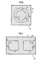
- a more injecting device 30 oriented towards the surface effect can be seen from FIG. 7, where the base body 22 is a truncated pyramid with a rectangular cross section. In the longitudinal extension of the rectangle, two truncated pyramids are inserted as inner bodies 23 in correspondingly counter-profiled bores 24. Each body 23 has two grooves 16 on the trapezoidal four circumferential surfaces to form nozzles 18, so that there are eight nozzles on each inner body 23, which form a square-like formation with their outlet cross sections.
- the taper of the bodies 23 and bores 24 can be self-locking.
- Base body 4, 19, 22 and sleeves 20 and inner body 6, 20, 21, 23 can optionally also have the same thickness in the longitudinal direction and, for example, polygonal or oval cross sections can also be used instead of a preferably round cross section for the bore, sleeve and inner body.
- the grooves 16, which also shape the nozzles 18, also being provided in the base body 4, 19, 22 or in base and inner bodies be.
- the base bodies 4, 19, 22 can in principle be pressed from more insulating refractory material compared to the sleeves 19, and inner bodies 6, 21, 23, which are more made from more wear-resistant refractory material.
- base bodies 4, 19, 22, sleeves 20 and inner bodies 6, 21, 23 are produced separately and then assembled with the metal jacket 7. Nevertheless, a joint production of base body, inner body and sleeve can be advantageous if a mold core made of a combustible or gasifiable substance is used, which has a footplate corresponding to the gas chamber 11 and stilts arranged thereon to form the gas nozzles 18. After inserting such a core into a shape formed according to the outer shape of the base body, the refractory material can be filled in and shaken, for example.
Landscapes
- Engineering & Computer Science (AREA)
- Chemical & Material Sciences (AREA)
- Mechanical Engineering (AREA)
- Manufacturing & Machinery (AREA)
- Materials Engineering (AREA)
- Metallurgy (AREA)
- Organic Chemistry (AREA)
- Carbon Steel Or Casting Steel Manufacturing (AREA)
- Furnace Charging Or Discharging (AREA)
- Treatment Of Steel In Its Molten State (AREA)
Priority Applications (1)
| Application Number | Priority Date | Filing Date | Title |
|---|---|---|---|
| AT86110485T ATE54174T1 (de) | 1985-10-30 | 1986-07-29 | Einduesvorrichtung fuer metallurgische gefaesse. |
Applications Claiming Priority (2)
| Application Number | Priority Date | Filing Date | Title |
|---|---|---|---|
| DE3538498 | 1985-10-30 | ||
| DE19853538498 DE3538498A1 (de) | 1985-10-30 | 1985-10-30 | Einduesvorrichtung fuer metallurgische gefaesse |
Publications (2)
| Publication Number | Publication Date |
|---|---|
| EP0221250A1 EP0221250A1 (de) | 1987-05-13 |
| EP0221250B1 true EP0221250B1 (de) | 1990-06-27 |
Family
ID=6284756
Family Applications (1)
| Application Number | Title | Priority Date | Filing Date |
|---|---|---|---|
| EP86110485A Expired - Lifetime EP0221250B1 (de) | 1985-10-30 | 1986-07-29 | Eindüsvorrichtung für metallurgische Gefässe |
Country Status (3)
| Country | Link |
|---|---|
| EP (1) | EP0221250B1 (Direct) |
| AT (1) | ATE54174T1 (Direct) |
| DE (2) | DE3538498A1 (Direct) |
Families Citing this family (23)
| Publication number | Priority date | Publication date | Assignee | Title |
|---|---|---|---|---|
| DE3716388C1 (de) * | 1987-05-15 | 1988-10-27 | Radex Deutschland Ag | Gasspuelstein |
| DE3717595A1 (de) * | 1987-05-25 | 1988-12-08 | Burbach & Bender Ohg | Gasspuelvorrichtung fuer metallurgische gefaesse |
| DE3727938C1 (de) * | 1987-08-21 | 1988-09-08 | Didier Werke Ag | Spuelstein |
| DE3802657C1 (Direct) * | 1988-01-29 | 1989-09-21 | Didier-Werke Ag, 6200 Wiesbaden, De | |
| DE3803093A1 (de) * | 1988-02-03 | 1989-08-17 | Didier Werke Ag | Verfahren und vorrichtung zur herstellung von bauteilen aus keramischem bzw. feuerfestem material mit durchgangskanaelen |
| DE3810098C1 (Direct) * | 1988-03-25 | 1989-03-23 | Radex-Heraklith Industriebeteiligungs Ag, Wien, At | |
| US4836433A (en) * | 1988-05-13 | 1989-06-06 | Insul Company, Inc. | Device for introducing stirring gas into molten metal in metered amount |
| DE3820611A1 (de) * | 1988-06-16 | 1989-12-21 | Burbach & Bender Ohg | Vorrichtung zur herstellung von bauteilen aus keramischem bzw. feuerfestem material mit mindestens einem eingearbeiteten schlitzfoermigen durchgangskanal |
| DE3833504A1 (de) * | 1988-10-01 | 1990-04-05 | Didier Werke Ag | Gasspueleinrichtung |
| DE3833503A1 (de) * | 1988-10-01 | 1990-04-05 | Didier Werke Ag | Gasspuelstein |
| DE3833506A1 (de) * | 1988-10-01 | 1990-04-05 | Didier Werke Ag | Vorrichtung zum aufspritzen einer ausbesserungsmasse auf einen lochstein |
| DE3833502A1 (de) * | 1988-10-01 | 1990-04-05 | Didier Werke Ag | Gasspuelstein |
| DE3907500C1 (en) * | 1989-03-08 | 1990-08-23 | Radex-Heraklith Industriebeteiligungs Ag, Wien, At | Gas bubble brick with directed porosity and method for its manufacture |
| DE4014509A1 (de) * | 1990-05-07 | 1991-11-14 | Didier Werke Ag | Gasspueler |
| US5249778A (en) * | 1992-04-14 | 1993-10-05 | Dolomitwerke Gmbh | Gas stir plug device with visual wear indicator |
| DE4410289C1 (de) * | 1994-03-25 | 1995-03-16 | Veitsch Radex Ag | Gasspüleinrichtung zum wandseitigen Einbau in metallurgische Schmelzgefäße |
| DE4411538C1 (de) * | 1994-04-02 | 1995-12-14 | Didier Werke Ag | Verfahren zum Herstellen einer Gas- und/oder Feststoffblaseinrichtung für metallurgische Gefäße, sowie nach dem Verfahren hergestellte Blaseinrichtung |
| DE19504941C2 (de) * | 1995-02-15 | 1998-05-20 | Knoellinger Horst | Gasspülstein |
| RU2152441C1 (ru) * | 1998-01-06 | 2000-07-10 | Акционерное общество "Кузнецкий металлургический комбинат" | Устройство для донной продувки стали в ковше |
| RU2132395C1 (ru) * | 1998-03-13 | 1999-06-27 | Открытое акционерное общество "Шибер" | Способ изготовления составной канальной пробки для продувки металла газом, огнеупорный материал для изготовления канальной пробки и способ изготовления каналообразующих элементов для выполнения каналов в пробке |
| DE19954918C2 (de) * | 1999-11-16 | 2001-09-20 | Veitsch Radex Gmbh Wien | Feuerfester keramischer Gasspülstein |
| RU2167206C1 (ru) * | 2000-04-05 | 2001-05-20 | Сороколет Геннадий Петрович | Фурма для донной продувки металла, способ изготовления фурмы и устройство для реализации способа |
| DE10326113B3 (de) * | 2003-06-06 | 2004-12-16 | Lwb Refractories Gmbh | Gasspüler mit geneigten schlitzförmigen Kanälen |
Family Cites Families (5)
| Publication number | Priority date | Publication date | Assignee | Title |
|---|---|---|---|---|
| GB1594631A (en) * | 1978-04-06 | 1981-08-05 | Electricity Council | Injectors for injecting gas into molten metal |
| DE8028296U1 (de) * | 1980-10-23 | 1981-05-27 | Arbed S.A., Luxembourg | Gasdurchlässiger Ausmauerungskörper aus feuerfestem Material |
| NL189008C (nl) * | 1981-11-18 | 1992-12-01 | Hoogovens Groep Bv | Gasdoorlatend wandelement voor een met vuurvast materiaal bekleed metallurgisch vat, in het bijzonder voor een l.d.-staalconverter. |
| DE3206499C1 (de) * | 1982-02-24 | 1988-03-03 | Didier-Werke Ag, 6200 Wiesbaden | Vorrichtung zum Einführen von Gasen in metallurgische Gefäße |
| LU85131A1 (de) * | 1983-12-12 | 1985-09-12 | Arbed | Gasdurchlaessiger baukoerper aus feuerfestem material |
-
1985
- 1985-10-30 DE DE19853538498 patent/DE3538498A1/de active Granted
-
1986
- 1986-07-29 DE DE8686110485T patent/DE3672275D1/de not_active Expired - Fee Related
- 1986-07-29 AT AT86110485T patent/ATE54174T1/de active
- 1986-07-29 EP EP86110485A patent/EP0221250B1/de not_active Expired - Lifetime
Non-Patent Citations (1)
| Title |
|---|
| PATENTS ABSTRACTS OF JAPAN, Band 9, Nr. 108 (C-280)[1831], 11. Mai 1985; & JP-A-60 2615 (NITSUSHIN SEIKOU K.K.) 08-01-1985 * |
Also Published As
| Publication number | Publication date |
|---|---|
| DE3538498C2 (Direct) | 1987-10-15 |
| DE3672275D1 (de) | 1990-08-02 |
| DE3538498A1 (de) | 1987-05-07 |
| ATE54174T1 (de) | 1990-07-15 |
| EP0221250A1 (de) | 1987-05-13 |
Similar Documents
| Publication | Publication Date | Title |
|---|---|---|
| EP0221250B1 (de) | Eindüsvorrichtung für metallurgische Gefässe | |
| EP0324043B1 (de) | Industriebrenner mit rekuperativer Luftvorwärmung, insbesondere zur Beheizung von Ofenräumen von Industrieöfen | |
| DE69027613T2 (de) | Strangpressdüse zum Extrudieren von Wabenstrukturen mit verdickter Aussenhaut | |
| DE63060T1 (de) | Extrusionskopf zum extrudieren eines hohlformlings mit mindestens einer materialschicht. | |
| DE2927488C2 (Direct) | ||
| DE4320723A1 (de) | Eintauchausguß | |
| DE19849814A1 (de) | Wasserstrahldüse in Wasserstrahlschneidköpfen | |
| EP1144836B1 (de) | Brennkammer-kühlstruktur für ein raketentriebwerk | |
| DE60004617T2 (de) | Verfahren zur herstellung eines flammenträgers | |
| DE3338185C2 (Direct) | ||
| DE3628066A1 (de) | Giessduese und verfahren zur herstellung einer giessduese | |
| DE2623425B2 (de) | Vorrichtung zum Kühlen einer Külbelform | |
| AT402735B (de) | Gasspülstein mit gerichteter porosität | |
| DE1165200B (de) | Schmelzspinnvorrichtung fuer Faeden od. dgl. aus organischen Polymeren | |
| DE4231686C2 (de) | Verschlußplatte für einen Schiebeverschluß an einem eine Metallschmelze enthaltenden Behälter | |
| DE2548854A1 (de) | Feuerfester stein mit einer durchlassoeffnung fuer fluessiges metall und verfahren zu dessen herstellung | |
| DE4041623A1 (de) | Duese fuer eine vorrichtung und ein verfahren zum hochgeschwindigkeitsflammenspritzen | |
| DE1231421B (de) | Entlueftungsvorrichtung fuer eine Vulkanisierform | |
| DE3238783A1 (de) | Filterkerze | |
| EP1420089B1 (de) | Vorrichtung zur Erzeugung von Fasern aus thermoplastischem Kunststoff | |
| DE2731113A1 (de) | Ausgussformstein und verfahren zu seiner herstellung | |
| DE3341491C1 (de) | Gasspuelstein fuer metallurgische Gefaesse | |
| DE4308685C2 (de) | Trennvorrichtung zum Trennen von Materialien unterschiedlicher Konsistenz | |
| EP1358922B1 (de) | Düse für insbesondere eine Druckstossreinigung von ringförmigen Gasfiltern | |
| DE3520783C2 (Direct) |
Legal Events
| Date | Code | Title | Description |
|---|---|---|---|
| PUAI | Public reference made under article 153(3) epc to a published international application that has entered the european phase |
Free format text: ORIGINAL CODE: 0009012 |
|
| 17P | Request for examination filed |
Effective date: 19860813 |
|
| AK | Designated contracting states |
Kind code of ref document: A1 Designated state(s): AT BE CH DE FR GB IT LI LU NL SE |
|
| 17Q | First examination report despatched |
Effective date: 19890124 |
|
| GRAA | (expected) grant |
Free format text: ORIGINAL CODE: 0009210 |
|
| AK | Designated contracting states |
Kind code of ref document: B1 Designated state(s): AT BE CH DE FR GB IT LI LU NL SE |
|
| PG25 | Lapsed in a contracting state [announced via postgrant information from national office to epo] |
Ref country code: IT Free format text: LAPSE BECAUSE OF FAILURE TO SUBMIT A TRANSLATION OF THE DESCRIPTION OR TO PAY THE FEE WITHIN THE PRE;WARNING: LAPSES OF ITALIAN PATENTS WITH EFFECTIVE DATE BEFORE 2007 MAY HAVE OCCURRED AT ANY TIME BEFORE 2007. THE CORRECT EFFECTIVE DATE MAY BE DIFFERENT FROM THE ONE RECORDED.SCRIBED TIME-LIMIT Effective date: 19900627 Ref country code: SE Effective date: 19900627 Ref country code: NL Effective date: 19900627 |
|
| REF | Corresponds to: |
Ref document number: 54174 Country of ref document: AT Date of ref document: 19900715 Kind code of ref document: T |
|
| ET | Fr: translation filed | ||
| PGFP | Annual fee paid to national office [announced via postgrant information from national office to epo] |
Ref country code: AT Payment date: 19900713 Year of fee payment: 5 |
|
| PGFP | Annual fee paid to national office [announced via postgrant information from national office to epo] |
Ref country code: FR Payment date: 19900717 Year of fee payment: 5 |
|
| PGFP | Annual fee paid to national office [announced via postgrant information from national office to epo] |
Ref country code: DE Payment date: 19900718 Year of fee payment: 5 Ref country code: GB Payment date: 19900718 Year of fee payment: 5 |
|
| GBT | Gb: translation of ep patent filed (gb section 77(6)(a)/1977) | ||
| PG25 | Lapsed in a contracting state [announced via postgrant information from national office to epo] |
Ref country code: CH Effective date: 19900731 Ref country code: LI Effective date: 19900731 Ref country code: LU Free format text: LAPSE BECAUSE OF NON-PAYMENT OF DUE FEES Effective date: 19900731 |
|
| REF | Corresponds to: |
Ref document number: 3672275 Country of ref document: DE Date of ref document: 19900802 |
|
| PGFP | Annual fee paid to national office [announced via postgrant information from national office to epo] |
Ref country code: BE Payment date: 19900808 Year of fee payment: 5 |
|
| NLV1 | Nl: lapsed or annulled due to failure to fulfill the requirements of art. 29p and 29m of the patents act | ||
| REG | Reference to a national code |
Ref country code: CH Ref legal event code: PL |
|
| PLBE | No opposition filed within time limit |
Free format text: ORIGINAL CODE: 0009261 |
|
| STAA | Information on the status of an ep patent application or granted ep patent |
Free format text: STATUS: NO OPPOSITION FILED WITHIN TIME LIMIT |
|
| 26N | No opposition filed | ||
| PG25 | Lapsed in a contracting state [announced via postgrant information from national office to epo] |
Ref country code: AT Effective date: 19910729 Ref country code: GB Effective date: 19910729 |
|
| PG25 | Lapsed in a contracting state [announced via postgrant information from national office to epo] |
Ref country code: BE Effective date: 19910731 |
|
| BERE | Be: lapsed |
Owner name: DIDIER-WERKE A.G. Effective date: 19910731 |
|
| GBPC | Gb: european patent ceased through non-payment of renewal fee | ||
| PG25 | Lapsed in a contracting state [announced via postgrant information from national office to epo] |
Ref country code: FR Effective date: 19920331 |
|
| PG25 | Lapsed in a contracting state [announced via postgrant information from national office to epo] |
Ref country code: DE Effective date: 19920401 |
|
| REG | Reference to a national code |
Ref country code: FR Ref legal event code: ST |