EP0220687B1 - Procédé et dispositif pour ouvrir et/ou fermer des capots de carrosseries automobiles - Google Patents
Procédé et dispositif pour ouvrir et/ou fermer des capots de carrosseries automobiles Download PDFInfo
- Publication number
- EP0220687B1 EP0220687B1 EP86114752A EP86114752A EP0220687B1 EP 0220687 B1 EP0220687 B1 EP 0220687B1 EP 86114752 A EP86114752 A EP 86114752A EP 86114752 A EP86114752 A EP 86114752A EP 0220687 B1 EP0220687 B1 EP 0220687B1
- Authority
- EP
- European Patent Office
- Prior art keywords
- handling device
- conveyor
- means according
- bonnets
- drive
- Prior art date
- Legal status (The legal status is an assumption and is not a legal conclusion. Google has not performed a legal analysis and makes no representation as to the accuracy of the status listed.)
- Expired - Lifetime
Links
Images


Classifications
-
- B—PERFORMING OPERATIONS; TRANSPORTING
- B05—SPRAYING OR ATOMISING IN GENERAL; APPLYING FLUENT MATERIALS TO SURFACES, IN GENERAL
- B05B—SPRAYING APPARATUS; ATOMISING APPARATUS; NOZZLES
- B05B13/00—Machines or plants for applying liquids or other fluent materials to surfaces of objects or other work by spraying, not covered by groups B05B1/00 - B05B11/00
- B05B13/02—Means for supporting work; Arrangement or mounting of spray heads; Adaptation or arrangement of means for feeding work
- B05B13/0292—Means for supporting work; Arrangement or mounting of spray heads; Adaptation or arrangement of means for feeding work devices for holding several workpieces to be sprayed in a spaced relationship, e.g. vehicle doors spacers
-
- B—PERFORMING OPERATIONS; TRANSPORTING
- B05—SPRAYING OR ATOMISING IN GENERAL; APPLYING FLUENT MATERIALS TO SURFACES, IN GENERAL
- B05B—SPRAYING APPARATUS; ATOMISING APPARATUS; NOZZLES
- B05B13/00—Machines or plants for applying liquids or other fluent materials to surfaces of objects or other work by spraying, not covered by groups B05B1/00 - B05B11/00
- B05B13/02—Means for supporting work; Arrangement or mounting of spray heads; Adaptation or arrangement of means for feeding work
- B05B13/04—Means for supporting work; Arrangement or mounting of spray heads; Adaptation or arrangement of means for feeding work the spray heads being moved during spraying operation
- B05B13/0447—Installation or apparatus for applying liquid or other fluent material to conveyed separate articles
- B05B13/0452—Installation or apparatus for applying liquid or other fluent material to conveyed separate articles the conveyed articles being vehicle bodies
-
- B—PERFORMING OPERATIONS; TRANSPORTING
- B62—LAND VEHICLES FOR TRAVELLING OTHERWISE THAN ON RAILS
- B62D—MOTOR VEHICLES; TRAILERS
- B62D65/00—Designing, manufacturing, e.g. assembling, facilitating disassembly, or structurally modifying motor vehicles or trailers, not otherwise provided for
- B62D65/02—Joining sub-units or components to, or positioning sub-units or components with respect to, body shell or other sub-units or components
- B62D65/06—Joining sub-units or components to, or positioning sub-units or components with respect to, body shell or other sub-units or components the sub-units or components being doors, windows, openable roofs, lids, bonnets, or weather strips or seals therefor
Definitions
- the invention relates to a method of the type specified in the preamble of the first claim and to an apparatus for carrying out the method as described in the preamble of claim 3.
- a device is exclusively known for closing hoods on motor vehicles. These hoods are held open by guide fingers of the upper transport device of the motor vehicle body. An opening of almost closed hoods on motor vehicle bodies is not known from this. Furthermore, the handling device known from this is carried along by coupling means from the transport device for the motor vehicle body. This has the disadvantage that when the handling device is jammed in its guide, it moves erratically. This leads to relative movements between the contact fingers of the handling device and the body, which leads to damage. After the known handling device has closed the opened hoods, the coupling means are released and the handling device is returned to its starting position by a separate drive.
- the object of the present invention is to automatically carry out this opening and, after the interior painting, the necessary closing of the hoods during the process of the motor vehicle body.
- the advantage here is that both the front and tailgate of a motor vehicle in the painting line can now be opened and closed fully automatically without the aid of a worker. This enables a fully automatic painting system to be set up, since the automatic opening and closing of the doors is already known.
- the method according to the invention ensures that damage to the motor vehicle body is excluded, since relative movements do not occur due to the synchronization of the movement of the body and the handling device.
- the movable arrangement of the handling device has the advantage that the opening / closing of the hood can be carried out while the body is being transported from one work station to another. This means that no additional processing time is required.
- the synchronization of the two speeds is achieved in a particularly simple and advantageous manner in that the handling device is positively moved via its stop against a counter-stop arranged on the transport device or the crossbar or the motor vehicle body, the synchronization of the movements is ensured.
- the features of claim 2 represent an additional safety device, since this avoids that the receiving device does not detect the hood to be actuated.
- a height adjustment of the handling device is not necessary as a result, since the handling device does not operate if the altitude deviates from the target range.
- Claim 3 describes an apparatus for performing the method according to the invention.
- This device is characterized in particular by the fact that it can be arranged laterally next to the transport device of the body, so that no delay occurs during the transport of the body. Rather, the hoods can be opened and closed during transport.
- the rotatable mounting of the swivel arm and the swiveling mounting of the actuating arm ensures that the handling device can be constructed in a narrow construction, since the gripping movements and swiveling movements of the grippers for actuating the hood can be swiveled or rotated into the travel path of the body.
- the development according to claim 4 describes an advantageous guide for the handling device.
- the straight guide is in turn held in a frame which is firmly connected to the floor or to the side walls of the workshop.
- the development according to claim 6 has the advantage that when the hood is pivoted there is no relative movement between the gripping device and the receiving device on the hood, so that this reliably prevents the gripping device from jumping out of the receiving device. Damage to the hoods to be operated is therefore excluded.
- a hereby particularly well harmonizing receiving device describes claim 7. This enables the hood to be actuated in a simple manner without having to touch the painted or painted surfaces.
- Claim 11 describes an environmentally friendly drive device for the handling device that can be used well in potentially explosive atmospheres.
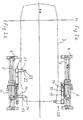
- the handling device is designated 1. It is on the floor 2 of a workshop, not shown.
- a motor vehicle body 3 is also shown in dash-dotted lines. This body 3 is moved on a transport device arranged on the floor 2 and not shown here. Between the transport device and the body 3 there is a mounting cross-member, also not shown, on which the body is rigidly attached.
- the handling device 1 has a frame 4, which is set up on the workshop floor 2. Two straight guides 5, which are arranged parallel to one another, are mounted in the frame 4. A slide 6 is guided by this straight guide 5. The carriage 6 is moved by a cylinder-piston unit 7 arranged on the frame 4.
- the swivel arm 9 is rotatably mounted on a support device 8. Its axis of rotation 10 is aligned horizontally, in such a way that it lies in the extension of the axis of rotation of the hood to be actuated.
- the front free end of the pivot arm 9 carries the actuating arm 11, which can be pivoted about a vertically arranged pivot axis 12.
- the front free end of the actuating arm 11 carries the gripping device 13 (Fig. 2a, b).
- the gripping device 13 has at its front free end a search pin 14 which is arranged in a stationary manner.
- An actuating bolt 15 arranged axially displaceably is provided parallel to it (FIG. 5).
- Both bolts 14, 15 work in a manner described in more detail below with a receiving device 16 arranged on the inside of the hood to be actuated. This consists of an eyelet 17 for the bolt 15 and an adjoining stop bracket 18 for the bolt 14 (Fig. 5,6).
- the docking unit 20 is arranged at the lower end of the slide 6. It consists of a cantilevered arm 21 projecting under the body 3, which carries at its front free end a lever 23 rotatably mounted about the axis 22. This lever 23 works together with a counter stop 24 (FIG. 3, 4) arranged on the crossmember.
- Fig. 2a the handling device 1 which is in the rest position is shown in plan view. It is suitable for opening and closing bonnets struck at the front.
- Fig. 2b the handling device 1 is shown, which is suitable for opening and closing trunk lids.
- the handling devices shown in both figures differ only in the position of the docking unit 20.
- the function of the two devices shown in FIGS. 2a, b is identical and is described further below.
- FIGS. 2a, b show a side view of the illustration according to FIGS. 2a, b.
- the mounting cross-member 25 which is carried and moved by the transport device 26.
- a counter stop 24 projecting laterally in the direction of the handling device 1 is fixedly arranged on the cross member 25.
- a prerequisite for the proper working of the handling device 1 is that a body 3 is mounted on a cross member 25 which is equipped with a counter stop 24, that the receiving device 16 is arranged in the gripping area of the gripping device 13 on the inside of the hood and that the hood with a Suitable lockable lock 27 (Fig. 5) and stop is equipped to prevent the hood from being both closed completely and only remaining in the open position if it would pivot automatically into the open position without a spring.
- the crosshead is moved by the transport device past the handling device arranged on the side.
- the counter stop 24 now deflects the lever 23 from the basic position shown in FIG. 4a.
- the deflection of the lever 23 will be larger or smaller (Fig. 4b).
- This twisting of the lever is detected by a measuring device. If the angle of rotation lies in a predetermined setpoint range, the handling device 1 knows that the body was delivered at the correct height, since the connection between the body and the crossbar is fixed. After driving over the lever 23, it is pivoted back into its starting position (FIG. 4a). This gives the cylinder-piston unit 7 compressed air and the slide 6 follows the leading body.
- the actuating arm 11 is pivoted through 90 ° in the direction of the body. Since in any case the hood to be actuated is not completely closed - either it is open or is held open a gap by the locking device 27 or the stop - the actuating arm with the search bolt 14 can thereby move into the gap between the hood and the body ( Fig. 6).
- the handling device 1 is constructed such that the axis of rotation 10 lies in the extension of the axes of rotation of the hood to be actuated. This reliably prevents no relative movement between the hood and the gripping device 13 when the hood is actuated.
- the actuating arm 11 nods downward. This nodding is supported by the fact that the hood, which is either fully open, cannot open further due to its articulation points or at. the hood is only held in this position by the arrester.
- the second bolt namely the actuating bolt 15
- the control device of the handling device 1 knows whether the hood is to be opened or closed.
- the swivel arm 9 now pivots back in the closing direction of the hood. As soon as the hood is closed except for a gap, it cannot be closed further due to the stop. The rotation of the swivel arm 9 is thereby stopped and to check whether the lock also holds the hood in the end position, the direction of rotation of the swivel arm 9 is reversed again in the opening direction. Since the hood is also locked by the lock 27 or cannot be brought out of its rest position due to its weight, the actuating arm 11 nods out again. As a result, the handling device 1 knows that the hood has reached its predetermined end position.
- the actuating pin 15 is then retracted and the actuating arm 11 is pivoted back. Reaching its initial position is recorded using appropriate measuring devices. As soon as these signals are present, the drive of the carriage 6 is switched off and the carriage is moved back to its starting position. A new work cycle can then be carried out.
- the hood to be operated is initially closed except for a gap and is secured in this position by the arrester against opening (the hood opens automatically due to the spring action), then - as soon as the search pin 14 and the actuating pin 15 engage in the receiving device 16 - by a further mechanism - for example an additional arm 19 (FIG. 5) - of the locking device can be released (FIG. 5a). Then the swivel arm 9 is also rotated here. As soon as the hood has reached its open position, the actuating arm 11 is nodded out again by rotating the swivel arm 9. As a result, the handling device 1 knows that the hood has reached its end position.
Landscapes
- Engineering & Computer Science (AREA)
- Manufacturing & Machinery (AREA)
- Chemical & Material Sciences (AREA)
- Combustion & Propulsion (AREA)
- Transportation (AREA)
- Mechanical Engineering (AREA)
- Automobile Manufacture Line, Endless Track Vehicle, Trailer (AREA)
Claims (11)
Applications Claiming Priority (2)
| Application Number | Priority Date | Filing Date | Title |
|---|---|---|---|
| DE19853538468 DE3538468A1 (de) | 1985-10-29 | 1985-10-29 | Verfahren und vorrichtung zum oeffnen und/oder schliessen von hauben an kraftfahrzeugkarosserien |
| DE3538468 | 1985-10-29 |
Publications (2)
| Publication Number | Publication Date |
|---|---|
| EP0220687A1 EP0220687A1 (fr) | 1987-05-06 |
| EP0220687B1 true EP0220687B1 (fr) | 1990-01-10 |
Family
ID=6284737
Family Applications (1)
| Application Number | Title | Priority Date | Filing Date |
|---|---|---|---|
| EP86114752A Expired - Lifetime EP0220687B1 (fr) | 1985-10-29 | 1986-10-23 | Procédé et dispositif pour ouvrir et/ou fermer des capots de carrosseries automobiles |
Country Status (2)
| Country | Link |
|---|---|
| EP (1) | EP0220687B1 (fr) |
| DE (2) | DE3538468A1 (fr) |
Cited By (5)
| Publication number | Priority date | Publication date | Assignee | Title |
|---|---|---|---|---|
| DE4021330A1 (de) * | 1990-07-03 | 1992-01-16 | Mannesmann Ag | Verfahren zum betrieb eines roboters und eine vorrichtung dazu |
| DE19547993A1 (de) * | 1995-12-21 | 1997-06-26 | Bayerische Motoren Werke Ag | Vorrichtung zum Fixieren von Kraftfahrzeugtüren während der Fahrzeugherstellung |
| DE19733004A1 (de) * | 1997-03-29 | 1998-10-01 | Volkswagen Ag | Klackformator oder ein Verfahren zum Lackieren einer Kraftfahrzeugkarosserie |
| DE10313463B3 (de) * | 2003-03-26 | 2004-04-29 | Daimlerchrysler Ag | Verfahren und Vorrichtung zum Durchführen einer Arbeitsoperation an einem bewegten Werkstück durch einen synchron mitbewegten Industrieroboter |
| DE102005016187B4 (de) * | 2005-04-08 | 2008-04-03 | Bayerische Motoren Werke Ag | Vorrichtung zum Öffnen von Klappen |
Families Citing this family (5)
| Publication number | Priority date | Publication date | Assignee | Title |
|---|---|---|---|---|
| DE19622768C2 (de) * | 1996-06-07 | 2003-11-06 | Bayerische Motoren Werke Ag | Bedienergeführtes Handhabungsgerät |
| DE19736559B4 (de) * | 1997-08-22 | 2007-02-01 | Micro Compact Car Smart Gmbh | Montageverfahren für eine Bremsanlage eines Kraftfahrzeuges |
| DE102008029345B4 (de) | 2008-06-20 | 2012-06-21 | Audi Ag | Vorrichtung zum Öffnen und Schließen einer Klappe |
| CN112313041A (zh) * | 2018-06-15 | 2021-02-02 | 杰艺科股份公司 | 用于移动交通工具主体的设备 |
| CN108909882B (zh) * | 2018-07-27 | 2023-10-13 | 台州豪鑫汽车部件有限公司 | 一种用于汽车前盖闭合装配的主体框架 |
Citations (4)
| Publication number | Priority date | Publication date | Assignee | Title |
|---|---|---|---|---|
| US3272347A (en) * | 1963-01-14 | 1966-09-13 | Jerome H Lemelson | Article manipulation apparatus |
| US4342535A (en) * | 1980-08-14 | 1982-08-03 | General Motors Corporation | Door-opener apparatus |
| GB2152882A (en) * | 1984-01-13 | 1985-08-14 | Durr Limited | Apparatus for lowering a part mounted for pivotal movement about a substantially horizontal axis on the body of a vehicle in a transport conveyor |
| EP0160407A1 (fr) * | 1984-04-27 | 1985-11-06 | Haden Drysys International Limited | Manipulateur et méthode pour ouvrir et/ou fermer des panneaux articulés et/ou glissants supportés par des châssis |
Family Cites Families (7)
| Publication number | Priority date | Publication date | Assignee | Title |
|---|---|---|---|---|
| DE186710C (fr) * | ||||
| FR2510933A1 (fr) * | 1981-08-06 | 1983-02-11 | Renault | Dispositif et procede de pose automatique d'un element de vitrage, d'une garniture de pavillon ou analogue |
| SE8204263L (sv) * | 1982-07-09 | 1984-01-10 | Alfa Laval Ab | Materialhanteringsrobot |
| DE3249454A1 (de) * | 1982-11-10 | 1984-05-10 | Audi Nsu Auto Union Ag, 7107 Neckarsulm | Verfahren zur montage von fertighimmeln in fahrzeugkarosserien |
| DE3301022A1 (de) * | 1983-01-14 | 1984-07-26 | Bayerische Motoren Werke AG, 8000 München | Manipulator |
| JPS59227572A (ja) * | 1983-06-08 | 1984-12-20 | Toyota Motor Corp | 自動車製造ラインにおける自動車ドア開閉装置 |
| DD238764A1 (de) * | 1985-06-28 | 1986-09-03 | Rostock Dieselmotoren | Manipulator |
-
1985
- 1985-10-29 DE DE19853538468 patent/DE3538468A1/de not_active Withdrawn
-
1986
- 1986-10-23 DE DE8686114752T patent/DE3668133D1/de not_active Expired - Lifetime
- 1986-10-23 EP EP86114752A patent/EP0220687B1/fr not_active Expired - Lifetime
Patent Citations (4)
| Publication number | Priority date | Publication date | Assignee | Title |
|---|---|---|---|---|
| US3272347A (en) * | 1963-01-14 | 1966-09-13 | Jerome H Lemelson | Article manipulation apparatus |
| US4342535A (en) * | 1980-08-14 | 1982-08-03 | General Motors Corporation | Door-opener apparatus |
| GB2152882A (en) * | 1984-01-13 | 1985-08-14 | Durr Limited | Apparatus for lowering a part mounted for pivotal movement about a substantially horizontal axis on the body of a vehicle in a transport conveyor |
| EP0160407A1 (fr) * | 1984-04-27 | 1985-11-06 | Haden Drysys International Limited | Manipulateur et méthode pour ouvrir et/ou fermer des panneaux articulés et/ou glissants supportés par des châssis |
Cited By (6)
| Publication number | Priority date | Publication date | Assignee | Title |
|---|---|---|---|---|
| DE4021330A1 (de) * | 1990-07-03 | 1992-01-16 | Mannesmann Ag | Verfahren zum betrieb eines roboters und eine vorrichtung dazu |
| DE19547993A1 (de) * | 1995-12-21 | 1997-06-26 | Bayerische Motoren Werke Ag | Vorrichtung zum Fixieren von Kraftfahrzeugtüren während der Fahrzeugherstellung |
| DE19733004A1 (de) * | 1997-03-29 | 1998-10-01 | Volkswagen Ag | Klackformator oder ein Verfahren zum Lackieren einer Kraftfahrzeugkarosserie |
| DE19733004B4 (de) * | 1997-03-29 | 2007-09-20 | Volkswagen Ag | Klackformator oder ein Verfahren zum Lackieren einer Kraftfahrzeugkarosserie |
| DE10313463B3 (de) * | 2003-03-26 | 2004-04-29 | Daimlerchrysler Ag | Verfahren und Vorrichtung zum Durchführen einer Arbeitsoperation an einem bewegten Werkstück durch einen synchron mitbewegten Industrieroboter |
| DE102005016187B4 (de) * | 2005-04-08 | 2008-04-03 | Bayerische Motoren Werke Ag | Vorrichtung zum Öffnen von Klappen |
Also Published As
| Publication number | Publication date |
|---|---|
| EP0220687A1 (fr) | 1987-05-06 |
| DE3668133D1 (de) | 1990-02-15 |
| DE3538468A1 (de) | 1987-04-30 |
Similar Documents
| Publication | Publication Date | Title |
|---|---|---|
| DE4100477A1 (de) | Vorrichtung zur behandlung von gegenstaenden | |
| EP0220687B1 (fr) | Procédé et dispositif pour ouvrir et/ou fermer des capots de carrosseries automobiles | |
| DE4201289C2 (de) | Vorrichtung zur Handhabung von Werkstücken | |
| DE8322699U1 (de) | Automatisch gesteuerte handhabungsvorrichtung | |
| DE102006050114A1 (de) | Positionierungsvorrichtung für beweglichen Teil eines Werkstücks | |
| EP1971516B1 (fr) | Procede et installation de montage de portes sur des carrosseries de vehicules | |
| WO2008080384A2 (fr) | Procédé pour monter ou démonter des pièces sur des composants de véhicule | |
| DE4019104C2 (fr) | ||
| DE102016003916A1 (de) | Lackierstation und zugehöriges Betriebsverfahren | |
| EP1748855B1 (fr) | Dispositif pour le deplacement pas a pas de pieces a usiner | |
| EP1366834B1 (fr) | Dispositif de changement d'outil pour presses | |
| EP2286927B1 (fr) | Installation de robot | |
| DE2725977A1 (de) | Vorrichtung zur handhabung von materialien | |
| EP0172837B1 (fr) | Installation pour retirer une piece a usiner d'un moule d'une presse d'injection ou d'une machine a coulee sous pression | |
| DE3622473A1 (de) | Positioniervorrichtung | |
| EP0157950B1 (fr) | Machine-outil avec une poupée mobile suivant plusieurs axes | |
| EP2492238A1 (fr) | Dispositif destiné à fermer des récipients | |
| DE2638312B2 (de) | Drehscheibensystem für schienengebundene Förderfahrzeuge | |
| EP3587025B1 (fr) | Dispositif de séparation compact | |
| EP1316487B1 (fr) | Installation de dépoussièrage pour carosserie de véhicule | |
| DE2910633C2 (fr) | ||
| DE1811133C3 (de) | Längs einer Förderbahn mit mehreren ihr zugeordneten Einzelarbeitsplätzen verlaufende Mitnehmervorrichtung zum Transport von Werkstückträgern | |
| DE19622768A1 (de) | Bedienergeführtes Handhabungsgerät | |
| EP1402970B1 (fr) | Dispositif de transfert de pièces pour presses de transfert | |
| WO2019170527A1 (fr) | Unité de pivotement destinée à un robot manipulateur et procédé associé |
Legal Events
| Date | Code | Title | Description |
|---|---|---|---|
| PUAI | Public reference made under article 153(3) epc to a published international application that has entered the european phase |
Free format text: ORIGINAL CODE: 0009012 |
|
| AK | Designated contracting states |
Kind code of ref document: A1 Designated state(s): DE FR GB IT SE |
|
| 17P | Request for examination filed |
Effective date: 19870415 |
|
| 17Q | First examination report despatched |
Effective date: 19881020 |
|
| GRAA | (expected) grant |
Free format text: ORIGINAL CODE: 0009210 |
|
| AK | Designated contracting states |
Kind code of ref document: B1 Designated state(s): DE FR GB IT SE |
|
| REF | Corresponds to: |
Ref document number: 3668133 Country of ref document: DE Date of ref document: 19900215 |
|
| GBT | Gb: translation of ep patent filed (gb section 77(6)(a)/1977) | ||
| ET | Fr: translation filed | ||
| ITF | It: translation for a ep patent filed |
Owner name: STUDIO JAUMANN |
|
| PLBE | No opposition filed within time limit |
Free format text: ORIGINAL CODE: 0009261 |
|
| STAA | Information on the status of an ep patent application or granted ep patent |
Free format text: STATUS: NO OPPOSITION FILED WITHIN TIME LIMIT |
|
| 26N | No opposition filed | ||
| PGFP | Annual fee paid to national office [announced via postgrant information from national office to epo] |
Ref country code: SE Payment date: 19911004 Year of fee payment: 6 |
|
| PGFP | Annual fee paid to national office [announced via postgrant information from national office to epo] |
Ref country code: DE Payment date: 19911015 Year of fee payment: 6 |
|
| PGFP | Annual fee paid to national office [announced via postgrant information from national office to epo] |
Ref country code: GB Payment date: 19911021 Year of fee payment: 6 |
|
| PGFP | Annual fee paid to national office [announced via postgrant information from national office to epo] |
Ref country code: FR Payment date: 19911030 Year of fee payment: 6 |
|
| ITTA | It: last paid annual fee | ||
| PG25 | Lapsed in a contracting state [announced via postgrant information from national office to epo] |
Ref country code: GB Effective date: 19921023 |
|
| PG25 | Lapsed in a contracting state [announced via postgrant information from national office to epo] |
Ref country code: SE Effective date: 19921024 |
|
| GBPC | Gb: european patent ceased through non-payment of renewal fee |
Effective date: 19921023 |
|
| PG25 | Lapsed in a contracting state [announced via postgrant information from national office to epo] |
Ref country code: FR Effective date: 19930630 |
|
| PG25 | Lapsed in a contracting state [announced via postgrant information from national office to epo] |
Ref country code: DE Effective date: 19930701 |
|
| REG | Reference to a national code |
Ref country code: FR Ref legal event code: ST |
|
| EUG | Se: european patent has lapsed |
Ref document number: 86114752.8 Effective date: 19930510 |
|
| PG25 | Lapsed in a contracting state [announced via postgrant information from national office to epo] |
Ref country code: IT Free format text: LAPSE BECAUSE OF NON-PAYMENT OF DUE FEES;WARNING: LAPSES OF ITALIAN PATENTS WITH EFFECTIVE DATE BEFORE 2007 MAY HAVE OCCURRED AT ANY TIME BEFORE 2007. THE CORRECT EFFECTIVE DATE MAY BE DIFFERENT FROM THE ONE RECORDED. Effective date: 20051023 |