EP0220687B1 - Method and apparatus for opening and/or closing the bonnets of automotive-vehicle bodies - Google Patents
Method and apparatus for opening and/or closing the bonnets of automotive-vehicle bodies Download PDFInfo
- Publication number
- EP0220687B1 EP0220687B1 EP86114752A EP86114752A EP0220687B1 EP 0220687 B1 EP0220687 B1 EP 0220687B1 EP 86114752 A EP86114752 A EP 86114752A EP 86114752 A EP86114752 A EP 86114752A EP 0220687 B1 EP0220687 B1 EP 0220687B1
- Authority
- EP
- European Patent Office
- Prior art keywords
- handling device
- conveyor
- means according
- bonnets
- drive
- Prior art date
- Legal status (The legal status is an assumption and is not a legal conclusion. Google has not performed a legal analysis and makes no representation as to the accuracy of the status listed.)
- Expired - Lifetime
Links
- 210000003660 reticulum Anatomy 0.000 title claims description 12
- 238000000034 method Methods 0.000 title claims description 9
- 230000001360 synchronised effect Effects 0.000 claims 1
- 238000010422 painting Methods 0.000 description 6
- 230000008901 benefit Effects 0.000 description 3
- 230000008878 coupling Effects 0.000 description 2
- 238000010168 coupling process Methods 0.000 description 2
- 238000005859 coupling reaction Methods 0.000 description 2
- 238000003032 molecular docking Methods 0.000 description 2
- 230000008569 process Effects 0.000 description 2
- 230000009471 action Effects 0.000 description 1
- 238000010276 construction Methods 0.000 description 1
- 239000002360 explosive Substances 0.000 description 1
- 238000009434 installation Methods 0.000 description 1
- 230000009191 jumping Effects 0.000 description 1
- 230000007246 mechanism Effects 0.000 description 1
- 239000007921 spray Substances 0.000 description 1
Images


Classifications
-
- B—PERFORMING OPERATIONS; TRANSPORTING
- B05—SPRAYING OR ATOMISING IN GENERAL; APPLYING FLUENT MATERIALS TO SURFACES, IN GENERAL
- B05B—SPRAYING APPARATUS; ATOMISING APPARATUS; NOZZLES
- B05B13/00—Machines or plants for applying liquids or other fluent materials to surfaces of objects or other work by spraying, not covered by groups B05B1/00 - B05B11/00
- B05B13/02—Means for supporting work; Arrangement or mounting of spray heads; Adaptation or arrangement of means for feeding work
- B05B13/0292—Means for supporting work; Arrangement or mounting of spray heads; Adaptation or arrangement of means for feeding work devices for holding several workpieces to be sprayed in a spaced relationship, e.g. vehicle doors spacers
-
- B—PERFORMING OPERATIONS; TRANSPORTING
- B05—SPRAYING OR ATOMISING IN GENERAL; APPLYING FLUENT MATERIALS TO SURFACES, IN GENERAL
- B05B—SPRAYING APPARATUS; ATOMISING APPARATUS; NOZZLES
- B05B13/00—Machines or plants for applying liquids or other fluent materials to surfaces of objects or other work by spraying, not covered by groups B05B1/00 - B05B11/00
- B05B13/02—Means for supporting work; Arrangement or mounting of spray heads; Adaptation or arrangement of means for feeding work
- B05B13/04—Means for supporting work; Arrangement or mounting of spray heads; Adaptation or arrangement of means for feeding work the spray heads being moved during spraying operation
- B05B13/0447—Installation or apparatus for applying liquid or other fluent material to conveyed separate articles
- B05B13/0452—Installation or apparatus for applying liquid or other fluent material to conveyed separate articles the conveyed articles being vehicle bodies
-
- B—PERFORMING OPERATIONS; TRANSPORTING
- B62—LAND VEHICLES FOR TRAVELLING OTHERWISE THAN ON RAILS
- B62D—MOTOR VEHICLES; TRAILERS
- B62D65/00—Designing, manufacturing, e.g. assembling, facilitating disassembly, or structurally modifying motor vehicles or trailers, not otherwise provided for
- B62D65/02—Joining sub-units or components to, or positioning sub-units or components with respect to, body shell or other sub-units or components
- B62D65/06—Joining sub-units or components to, or positioning sub-units or components with respect to, body shell or other sub-units or components the sub-units or components being doors, windows, openable roofs, lids, bonnets, or weather strips or seals therefor
Definitions
- the invention relates to a method of the type specified in the preamble of the first claim and to an apparatus for carrying out the method as described in the preamble of claim 3.
- a device is exclusively known for closing hoods on motor vehicles. These hoods are held open by guide fingers of the upper transport device of the motor vehicle body. An opening of almost closed hoods on motor vehicle bodies is not known from this. Furthermore, the handling device known from this is carried along by coupling means from the transport device for the motor vehicle body. This has the disadvantage that when the handling device is jammed in its guide, it moves erratically. This leads to relative movements between the contact fingers of the handling device and the body, which leads to damage. After the known handling device has closed the opened hoods, the coupling means are released and the handling device is returned to its starting position by a separate drive.
- the object of the present invention is to automatically carry out this opening and, after the interior painting, the necessary closing of the hoods during the process of the motor vehicle body.
- the advantage here is that both the front and tailgate of a motor vehicle in the painting line can now be opened and closed fully automatically without the aid of a worker. This enables a fully automatic painting system to be set up, since the automatic opening and closing of the doors is already known.
- the method according to the invention ensures that damage to the motor vehicle body is excluded, since relative movements do not occur due to the synchronization of the movement of the body and the handling device.
- the movable arrangement of the handling device has the advantage that the opening / closing of the hood can be carried out while the body is being transported from one work station to another. This means that no additional processing time is required.
- the synchronization of the two speeds is achieved in a particularly simple and advantageous manner in that the handling device is positively moved via its stop against a counter-stop arranged on the transport device or the crossbar or the motor vehicle body, the synchronization of the movements is ensured.
- the features of claim 2 represent an additional safety device, since this avoids that the receiving device does not detect the hood to be actuated.
- a height adjustment of the handling device is not necessary as a result, since the handling device does not operate if the altitude deviates from the target range.
- Claim 3 describes an apparatus for performing the method according to the invention.
- This device is characterized in particular by the fact that it can be arranged laterally next to the transport device of the body, so that no delay occurs during the transport of the body. Rather, the hoods can be opened and closed during transport.
- the rotatable mounting of the swivel arm and the swiveling mounting of the actuating arm ensures that the handling device can be constructed in a narrow construction, since the gripping movements and swiveling movements of the grippers for actuating the hood can be swiveled or rotated into the travel path of the body.
- the development according to claim 4 describes an advantageous guide for the handling device.
- the straight guide is in turn held in a frame which is firmly connected to the floor or to the side walls of the workshop.
- the development according to claim 6 has the advantage that when the hood is pivoted there is no relative movement between the gripping device and the receiving device on the hood, so that this reliably prevents the gripping device from jumping out of the receiving device. Damage to the hoods to be operated is therefore excluded.
- a hereby particularly well harmonizing receiving device describes claim 7. This enables the hood to be actuated in a simple manner without having to touch the painted or painted surfaces.
- Claim 11 describes an environmentally friendly drive device for the handling device that can be used well in potentially explosive atmospheres.
- the handling device is designated 1. It is on the floor 2 of a workshop, not shown.
- a motor vehicle body 3 is also shown in dash-dotted lines. This body 3 is moved on a transport device arranged on the floor 2 and not shown here. Between the transport device and the body 3 there is a mounting cross-member, also not shown, on which the body is rigidly attached.
- the handling device 1 has a frame 4, which is set up on the workshop floor 2. Two straight guides 5, which are arranged parallel to one another, are mounted in the frame 4. A slide 6 is guided by this straight guide 5. The carriage 6 is moved by a cylinder-piston unit 7 arranged on the frame 4.
- the swivel arm 9 is rotatably mounted on a support device 8. Its axis of rotation 10 is aligned horizontally, in such a way that it lies in the extension of the axis of rotation of the hood to be actuated.
- the front free end of the pivot arm 9 carries the actuating arm 11, which can be pivoted about a vertically arranged pivot axis 12.
- the front free end of the actuating arm 11 carries the gripping device 13 (Fig. 2a, b).
- the gripping device 13 has at its front free end a search pin 14 which is arranged in a stationary manner.
- An actuating bolt 15 arranged axially displaceably is provided parallel to it (FIG. 5).
- Both bolts 14, 15 work in a manner described in more detail below with a receiving device 16 arranged on the inside of the hood to be actuated. This consists of an eyelet 17 for the bolt 15 and an adjoining stop bracket 18 for the bolt 14 (Fig. 5,6).
- the docking unit 20 is arranged at the lower end of the slide 6. It consists of a cantilevered arm 21 projecting under the body 3, which carries at its front free end a lever 23 rotatably mounted about the axis 22. This lever 23 works together with a counter stop 24 (FIG. 3, 4) arranged on the crossmember.
- Fig. 2a the handling device 1 which is in the rest position is shown in plan view. It is suitable for opening and closing bonnets struck at the front.
- Fig. 2b the handling device 1 is shown, which is suitable for opening and closing trunk lids.
- the handling devices shown in both figures differ only in the position of the docking unit 20.
- the function of the two devices shown in FIGS. 2a, b is identical and is described further below.
- FIGS. 2a, b show a side view of the illustration according to FIGS. 2a, b.
- the mounting cross-member 25 which is carried and moved by the transport device 26.
- a counter stop 24 projecting laterally in the direction of the handling device 1 is fixedly arranged on the cross member 25.
- a prerequisite for the proper working of the handling device 1 is that a body 3 is mounted on a cross member 25 which is equipped with a counter stop 24, that the receiving device 16 is arranged in the gripping area of the gripping device 13 on the inside of the hood and that the hood with a Suitable lockable lock 27 (Fig. 5) and stop is equipped to prevent the hood from being both closed completely and only remaining in the open position if it would pivot automatically into the open position without a spring.
- the crosshead is moved by the transport device past the handling device arranged on the side.
- the counter stop 24 now deflects the lever 23 from the basic position shown in FIG. 4a.
- the deflection of the lever 23 will be larger or smaller (Fig. 4b).
- This twisting of the lever is detected by a measuring device. If the angle of rotation lies in a predetermined setpoint range, the handling device 1 knows that the body was delivered at the correct height, since the connection between the body and the crossbar is fixed. After driving over the lever 23, it is pivoted back into its starting position (FIG. 4a). This gives the cylinder-piston unit 7 compressed air and the slide 6 follows the leading body.
- the actuating arm 11 is pivoted through 90 ° in the direction of the body. Since in any case the hood to be actuated is not completely closed - either it is open or is held open a gap by the locking device 27 or the stop - the actuating arm with the search bolt 14 can thereby move into the gap between the hood and the body ( Fig. 6).
- the handling device 1 is constructed such that the axis of rotation 10 lies in the extension of the axes of rotation of the hood to be actuated. This reliably prevents no relative movement between the hood and the gripping device 13 when the hood is actuated.
- the actuating arm 11 nods downward. This nodding is supported by the fact that the hood, which is either fully open, cannot open further due to its articulation points or at. the hood is only held in this position by the arrester.
- the second bolt namely the actuating bolt 15
- the control device of the handling device 1 knows whether the hood is to be opened or closed.
- the swivel arm 9 now pivots back in the closing direction of the hood. As soon as the hood is closed except for a gap, it cannot be closed further due to the stop. The rotation of the swivel arm 9 is thereby stopped and to check whether the lock also holds the hood in the end position, the direction of rotation of the swivel arm 9 is reversed again in the opening direction. Since the hood is also locked by the lock 27 or cannot be brought out of its rest position due to its weight, the actuating arm 11 nods out again. As a result, the handling device 1 knows that the hood has reached its predetermined end position.
- the actuating pin 15 is then retracted and the actuating arm 11 is pivoted back. Reaching its initial position is recorded using appropriate measuring devices. As soon as these signals are present, the drive of the carriage 6 is switched off and the carriage is moved back to its starting position. A new work cycle can then be carried out.
- the hood to be operated is initially closed except for a gap and is secured in this position by the arrester against opening (the hood opens automatically due to the spring action), then - as soon as the search pin 14 and the actuating pin 15 engage in the receiving device 16 - by a further mechanism - for example an additional arm 19 (FIG. 5) - of the locking device can be released (FIG. 5a). Then the swivel arm 9 is also rotated here. As soon as the hood has reached its open position, the actuating arm 11 is nodded out again by rotating the swivel arm 9. As a result, the handling device 1 knows that the hood has reached its end position.
Landscapes
- Engineering & Computer Science (AREA)
- Manufacturing & Machinery (AREA)
- Chemical & Material Sciences (AREA)
- Combustion & Propulsion (AREA)
- Transportation (AREA)
- Mechanical Engineering (AREA)
- Automobile Manufacture Line, Endless Track Vehicle, Trailer (AREA)
Description
Die Erfindung bezieht sich auf ein Verfahren der im Oberbegriff des ersten Anspruchs angegebenen Art sowie auf eine Vorrichtung zur Durchführung des Verfahrens, wie es der Oberbegriff des Anspruchs 3 beschreibt.The invention relates to a method of the type specified in the preamble of the first claim and to an apparatus for carrying out the method as described in the preamble of
Beim Lackieren von Kraftfahrzeugkarosserien ist es bekannt, Spritzroboter zur Innen- und Außenlackierung einzusetzen. Hierbei ist es notwendig, daß nach erfolgter Außenlackierung die von den Hauben verschlossenen Innenräume geöffnet werden müssen. Bisher wurde dies von Hand durchgeführt, indem ein Werker die von einem Anschlagstift gehaltene spaltbreit geöffnete Klappe von Hand öffnete.When painting motor vehicle bodies, it is known to use spray robots for interior and exterior painting. It is necessary here that after the exterior painting has been carried out, the interiors closed by the hoods must be opened. Previously, this was done by hand, when a worker manually opened the flap, which was held open by a stop pin, by hand.
Aus der GB-A 2 152 882 ist eine Vorrichtung ausschließlich zum Schließen von Hauben an Kraftfahrzeugen bekannt. Diese Hauben werden im geöffneten Zustand durch Führungsfinger der oberen Transporteinrichtung der Kraftfahrzeugkarosserie aufgehalten. Ein Öffnen von nahezu geschlossenen Hauben an Kraftfahrzeugkarosserien ist daraus nicht bekannt. Weiterhin wird die hieraus bekannte Handlingeinrichtung über Kupplungsmittel von der Transporteinrichtung für die Kraftfahrzeugkarosserie mitgeschleppt. Dies hat den Nachteil, daß bei einem Klemmen der Handlingeinrichtung in ihrer Führung diese sich sprunghaft bewegt. Dadurch kommt es zu Relativbewegungen zwischen den Berührungsfingern der Handlingeinrichtung und der Karosse, was zu Beschädigungen führt. Nachdem die bekannte Handlingeinrichtung die geöffneten Hauben geschlossen hat, werden die Kupplungsmittel gelöst und die Handlingeinrichtung wird von einem separaten Antrieb in ihre Ausgangslage zurückgefahren.From GB-A 2 152 882 a device is exclusively known for closing hoods on motor vehicles. These hoods are held open by guide fingers of the upper transport device of the motor vehicle body. An opening of almost closed hoods on motor vehicle bodies is not known from this. Furthermore, the handling device known from this is carried along by coupling means from the transport device for the motor vehicle body. This has the disadvantage that when the handling device is jammed in its guide, it moves erratically. This leads to relative movements between the contact fingers of the handling device and the body, which leads to damage. After the known handling device has closed the opened hoods, the coupling means are released and the handling device is returned to its starting position by a separate drive.
Aufgabe der vorliegenden Erfindung ist es, dieses Öffnen und nach dem Innenlackieren notwendige Schließen der Hauben während des Verfahrens der Kraftfahrzeugkarosserie automatisch durchzuführen.The object of the present invention is to automatically carry out this opening and, after the interior painting, the necessary closing of the hoods during the process of the motor vehicle body.
Gelöst wird diese Aufgabe durch die Merkmale des ersten Anspruchs. Vorteilhaft hierbei ist, daß nunmehr vollautomatisch ohne Zuhilfenahme eines Werkers sowohl Front- wie Heckklappe eines Kraftfahrzeuges in der Lackierstraße geöffnet und geschlossen werden können. Damit kann eine vollautomatisch arbeitende Lackieranlage aufgebaut werden, da das automatische Öffnen und Schließen der Türen bereits bekannt ist. Durch das erfindungsgemäße Verfahren ist sichergestellt, daß eine Beschädigung der Kraftfahrzeugkarosserie ausgeschlossen ist, da durch die Synchronisierung der Bewegung der Karosserie und des Handlinggerätes Relativbewegungen nicht auftreten. Durch die verfahrbare Anordnung der Handlingeinrichtung wird der Vorteil erzielt, daß das Öffnen/Schließen der Haube während des Transports der Karosse von einer Arbeitsstation zur anderen durchgeführt werden kann. Hierdurch wird keine zusätzliche Bearbeitungszeit benötigt.This problem is solved by the features of the first claim. The advantage here is that both the front and tailgate of a motor vehicle in the painting line can now be opened and closed fully automatically without the aid of a worker. This enables a fully automatic painting system to be set up, since the automatic opening and closing of the doors is already known. The method according to the invention ensures that damage to the motor vehicle body is excluded, since relative movements do not occur due to the synchronization of the movement of the body and the handling device. The movable arrangement of the handling device has the advantage that the opening / closing of the hood can be carried out while the body is being transported from one work station to another. This means that no additional processing time is required.
Das Synchronisieren der beiden Geschwindigkeiten wird auf besonders einfache und vorteilhafte Weise dadurch erzielt, daß die Handlingeinrichtung über ihren Anschlag gegen einen an der Transporteinrichtung oder der Traverse oder der Kraftfahrzeugkarosserie angeordneten Gegenanschlag kraftschlüssig gefahren wird, ist die Synchronisierung der Bewegungen gesichert.The synchronization of the two speeds is achieved in a particularly simple and advantageous manner in that the handling device is positively moved via its stop against a counter-stop arranged on the transport device or the crossbar or the motor vehicle body, the synchronization of the movements is ensured.
Die Merkmale des Anspruchs 2 stellen eine zusätzliche Sicherheitseinrichtung dar, da hierdurch vermieden wird, daß die Aufnahmeeinrichtung die zu betätigende Haube nicht erfaßt. Zudem ist hierdurch eine Höhenverstellung der Handlingeinrichtung nicht notwendig, da bei einer aus dem Sollbereich abweichenden Höhenlage die Handlingeinrichtung nicht tätig wird.The features of
Anspruch 3 beschreibt eine Vorrichtung zur Durchführung des erfindungsgemäßen Verfahrens. Diese Vorrichtung zeichnet sich insbesondere dadurch aus, daß sie seitlich neben der Transporteinrichtung der Karosserie angeordnet werden kann, so daß während des Transportes der Karosserie keine Verzögerung auftritt. Das Öffnen und Schließen der Hauben kann vielmehr während des Transportes durchgeführt werden. Durch die drehbare Lagerung des Schwenkarmes sowie die verschwenkbare Lagerung des Betätigungsarmes wird erreicht, daß die Handlingeinrichtung schmalbauend aufgebaut werden kann, da durch die Drehbewegungen und Verschwenkbewegungen der Greifer zum Betätigen der Haube in den Verfahrweg der Karosserie eingeschwenkt bzw. gedreht werden kann.
Weiterhin ist eine einfache Kontrollmöglichkeit gegeben, wenn die Haube vollständig geöffnet oder geschlossen wird. Denn dann ist die Haube nicht mehr weiterverschwenkbar und der Betätigungsarm wird bei einer weiteren Verschwenkbewegung gekippt. Zudem wird dadurch sichergestellt, daß die Greifeinrichtung der Handlingeinrichtung die Haube nicht zu früh losläßt, so daß die Haube in einer undefinierten Lage stehenbleibt.There is also a simple control option when the hood is fully opened or closed. Because then the hood can no longer be pivoted further and the actuating arm is tilted during a further pivoting movement. This also ensures that the gripping device of the handling device does not let go of the hood too early, so that the hood remains in an undefined position.
Die Weiterbildung nach Anspruch 4 beschreibt eine vorteilhafte Führung für die Handlingeinrichtung. Die Geradführung ist wiederum in einem Gestell gehalten, welches fest mit dem Boden oder mit Seitenwänden der Werkshalle verbunden ist.The development according to
Die Weiterbildung nach Anspruch 5 beschreibt vorteilhafte Anordnungen der einzelnen Achsen. Hierdurch wird bei kleinstmöglichem Bauraum eine größtmögliche Bewegungsfläche der Handlingeinrichtung erzielt.The development according to
Die Weiterbildung nach Anspruch 6 hat den Vorteil, daß beim Verschwenken der Haube keine Relativbewegung zwischen der Greifeinrichtung und der Aufnahmeeinrichtung an der Haube stattfindet, so daß hierdurch sicher vermieden wird, daß die Greifeinrichtung aus der Aufnahmeeinrichtung herausspringt bzw. hebelt. Beschädigungen der zu betätigenden Hauben sind damit ausgeschlossen.The development according to
Eine hiermit besonders gut harmonierende Aufnahmeeinrichtung beschreibt Anspruch 7. Hierdurch wird auf einfache Art und Weise die Betätigung der Haube möglich, ohne daß die lackierte bzw. zu lackierenden Flächen berührt werden müssen.A hereby particularly well harmonizing receiving device describes
Mit der Weiterbildung nach Anspruch 8 läßt sich zum einen feststellen, ob überhaupt eine Karosse vorhanden ist und gleichzeitig eine Abfrage ihrer Höhenlage durchführen. Ebenso kann durch ein Verschwenken in Gegenrichtung festgestellt werden, daß die Synchronisierung der beiden Geschwindigkeiten erfolgt ist.With the development according to claim 8, it can be determined on the one hand whether there is a body at all and at the same time a query of it Carry out altitude. It can also be determined by pivoting in the opposite direction that the synchronization of the two speeds has taken place.
Um zu verhindern, daß die Handlingeinrichtung ruckartige Bewegungen ausführt, so daß es während des Betätigens der Haube zu Relativbewegungen zwischen Handlingeinrichtung und Haube kommt, wird die Weiterbildung nach Anspruch 10 vorgeschlagen.In order to prevent the handling device from performing jerky movements, so that relative movements between the handling device and the hood occur during the actuation of the hood, the development according to
Eine umweltfreundliche und in explosionsgefährdeten Räumen gut anzuwendende Antriebseinrichtung für die Handlingeinrichtung beschreibt Anspruch 11.
Im folgenden wird die Erfindung anhand eines bevorzugten Ausführungsbeispiels näher dargestellt.The invention is illustrated in more detail below on the basis of a preferred exemplary embodiment.
Es stellen dar:
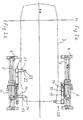
- Fig. 1 eine Seitenansicht einer erfindungsgemäß aufgebauten Handlingeinrichtung;
- Fig. 2a, b eine Draufsicht auf die Handlingeinrichtung in Ruhestellung und in Arbeitsstellung;
- Fig. 3a, b Seitenansichten nach Fig. 2a, b;
- Fig. 4a-c Einzelheiten des Synchronisiervorganges zwischen den Geschwindigkeiten der Transporteinrichtung und der Handlingeinrichtung;
- Fig. 5a, b Seiten- und Draufsicht auf die Greifeinrichtung beim Öffnen einer Kofferraumhaube eines Kraftfahrzeuges;
- Fig. 6a, b Seiten- und Draufsichten auf die Greifeinrichtung beim Öffnen einer Motorhaube eines Kraftfahrzeuges.
- 1 shows a side view of a handling device constructed according to the invention;
- 2a, b a top view of the handling device in the rest position and in the working position;
- Fig. 3a, b side views of Fig. 2a, b;
- 4a-c details of the synchronization process between the speeds of the transport device and the handling device;
- 5a, b side and top view of the gripping device when opening a trunk hood of a motor vehicle;
- Fig. 6a, b side and top views of the gripping device when opening a hood of a motor vehicle.
In Fig. 1 ist die erfindungsgemäße Handlingeinrichtung mit 1 bezeichnet. Sie steht auf dem Boden 2 einer nicht weiter dargestellten Werkhalle. In strichpunktierten Linien ist weiterhin eine Kraftfahrzeugkarosse 3 dargestellt Diese Karosse 3 wird auf einer auf dem Boden 2 angeordneten, hier nicht näher dargestellten Transporteinrichtung verfahren. Zwischen Transporteinrichtung und Karosse 3 ist eine ebenfalls nicht dargestellte Montagetraverse vorhanden, auf der die Karosse starr befestigt ist.In Fig. 1, the handling device according to the invention is designated 1. It is on the
Die Handlingeinrichtung 1 weist einen Rahmen 4 auf, der auf dem Werkhallenboden 2 aufgestellt ist. In dem Rahmen 4 sind zwei Geradführungen 5, die parallel zueinander angeordnet sind, gelagert. Von dieser Geradführung 5 wird ein Schlitten 6 geführt. Verfahren wird der Schlitten 6 von einer an dem Rahmen 4 angeordneten Zylinder-Kolben-Einheit 7.The
Auf dem oberen Ende des Schlittens 6 ist an einer Trageinrichtung 8 der Schwenkarm 9 drehbar gelagert. Seine Drehachse 10 ist horizontal ausgerichtet, und zwar derart, daß sie in der Verlängerung der Drehachse der zu betätigenden Haube liegt. Das vordere freie Ende des Schwenkarmes 9 trägt den Betätigungsarm 11, welcher um eine vertikal angeordnete Schwenkachse 12 verschwenkbar ist. Das vordere freie Ende des Betätigungsarmes 11 trägt die Greifeinrichtung 13 (Fig. 2a,b).On the upper end of the
Die Greifeinrichtung 13 weist an ihrem vorderen freien Ende einen Suchbolzen 14 auf, der ortsfest angeordnet ist. Parallel zu ihm ist ein axial verfahrbar angeordneter Betätigungsbolzen 15 vorgesehen (Fig. 5).The
Beide Bolzen 14, 15 arbeiten in einer weiter unten näher beschriebenen Art mit einer auf der Innenseite der zu betätigenden Haube angeordneten Aufnahmeeinrichtung 16 zusammen. Diese besteht aus einer Öse17 für den Bolzen 15 und einem sich daran anschließenden Anschlagbügel 18 für den Bolzen 14 (Fig. 5,6).Both
Am unteren Ende des Schlittens 6 ist die Andockeinheit 20 angeordnet. Sie besteht aus einem auskragend unter die Karosse 3 ragenden Arm 21, welcher an seinem vorderen freien Ende einen um die Achse 22 drehbar gelagerten Hebel 23 trägt. Dieser Hebel 23 arbeitet mit einem an der Traverse angeordneten Gegenanschlag 24 (Fig. 3,4) zusammen.The
In Fig. 2a ist in der Draufsicht die in Ruhestellung befindliche Handlingeinrichtung 1 dargestellt. Sie eignet sich zum Öffnen und Schließen von vorne angeschlagenen Motorhauben.In Fig. 2a, the
In Fig. 2b ist die Handlingeinrichtung 1 dargestellt, welche zum Öffnen und Schließen von Kofferraumhauben geeignet ist. Die in beiden Abbildungen dargestellten Handlingeinrichtungen unterscheiden sich nur durch die Lage der Andockeinheit 20. Die Funktion der beiden in Fig. 2a,b dargestellten Einrichtungen ist identisch und wird weiter hinten beschrieben.In Fig. 2b, the
In Fig. 3 a,b ist eine Seitenansicht der Darstellung nach Fig. 2a,b dargestellt. Hier sieht man auch die Montagetraverse 25, die von der Transporteinrichtung 26 getragen und bewegt wird. An der Traverse 25 ist ein seitlich in Richtung auf die Handlingeinrichtung 1 herausragender Gegenanschlag 24 fest angeordnet.3a, b show a side view of the illustration according to FIGS. 2a, b. Here you can also see the mounting
Im folgenden wird die Erfindung unter Zuhilfenahme der Fig. 4 - 6 näher beschrieben.The invention is described in more detail below with the aid of FIGS. 4-6.
Vorraussetzung zum ordnungsgemäßem Arbeiten der Handlingeinrichtung 1 ist, daß eine Karosse 3 auf einer Traverse 25 montiert ist, die mit einem Gegenanschlag 24 ausgerüstet ist, daß auf der Innenseite der Haube die Aufnahmeeinrichtung 16 im Greifbereich der Greifeinrichtung 13 angeordnet ist und daß die Haube mit einem geeigneten rastbaren Feststeller 27 (Fig. 5) und Anschlag ausgerüstet ist, die verhindern, daß die Haube sowohl vollständig geschlossen wird als auch nur in Öffnungsstellung stehen bleibt, wenn sie durch Federkraft selbsttätig ohne Feststeller in die Öffnungsstellung verschwenken würde.A prerequisite for the proper working of the
Die Traverse wird von der Transporteinrichtung an der seitlich angeordneten Handlingeinrichtung vorbeibewegt. Beim Vorbeifahren lenkt nun der Gegenanschlag 24 den Hebel 23 aus der in Fig. 4a gezeigten Grundstellung aus. Je nach Höhenlage des Gegenanschlages wird die Auslenkung des Hebels 23 größer oder kleiner ausfallen (Fig. 4b). Dieses Verdrehen des Hebels wird von einer Meßeinrichtung erfaßt. Liegt der Verdrehwinkel in einem vorgegebenen Sollwertbereich, so weiß die Handlingeinrichtung 1, daß die Karosse in der richtigen Höhenlage angeliefert wurde, da die Verbindung Karosse Traverse fest ist. Nach Überfahren des Hebels 23 wird dieser wieder in seine Ausgangslage (Fig. 4a) zurückgeschwenkt. Dadurch erhält die Zylinder-Kolben-Einheit 7 Druckluft und der Schlitten 6 fährt der voreilenden Karosse nach. Da seine Geschwindigkeit größer ist als die Geschwindigkeit der Transporteinrichtung 26, holt er die Karosse 3 ein. Am Überholen der Karosse 3 wird der Schlitten dadurch gehindert, daß der Hebel 23 gegen einen an der Traverse 25 angeordneten ortsfesten Anschlag fährt, der auch der Gegenanschlag 24 sein kann (Fig. 4a). Hierdurch wird der Hebel 23 entgegen der ersten Drehrichtung senkrecht gestellt (Fig. 4c). Durch dieses Verdrehen wird der Meßeinrichtung signalisiert, daß der Schlitten die Traverse erreicht hat. Da der Antrieb des Schlittens 6 eingeschaltet bleibt, folgt er kraftschlüssig der Karosse 3.The crosshead is moved by the transport device past the handling device arranged on the side. When driving past, the counter stop 24 now deflects the
Gleichzeitig wird nach diesem Synchronisieren der beiden Verfahrgeschwindigkeiten der Betätigungsarm 11 um 90° in Richtung auf die Karosse verschwenkt. Da in jedem Fall die zu betätigende Haube nicht vollständig geschlossen ist, - entweder ist sie geöffnet oder wird von dem Feststeller 27 bzw. Anschlag spaltbreit geöffnet gehalten - kann dadurch der Betätigungsarm mit dem Suchbolzen 14 in den Spalt zwischen der Haube und der Karosse einfahren (Fig. 6).At the same time, after this synchronization of the two travel speeds, the
Danach wird der Schwenkarm 9 verdreht. Die Handlingeinrichtung 1 ist derart aufgebaut, daß die Drehachse 10 in der Verlängerung der Drehachsen der zu betätigenden Haube liegt. Dadurch wird sicher vermieden, daß keine Relativbewegung beim Betätigen der Haube zwischen der Haube und der Greifeinrichtung 13 auftritt.Then the
Sobald durch die Drehbewegung des Schwenkarmes 9 der Suchbolzen 14 gegen den Anschlagbügel 17 stößt, nickt der Betätigungsarm 11 nach unten aus. Dieses Ausnicken wird dadurch unterstützt, daß die entweder voll geöffnete Haube nicht weiter öffnen kann aufgrund ihrer Anlenkpunkte oder bei . nur spaltweise geöffneter Haube die Haube in dieser Stellung durch den Feststeller gehalten wird.As soon as the
Sobald der Betätigungsarm 11 ausgenickt wurde, wird der zweite Bolzen, nähmlich der Betätigungsbolzen 15 ausgefahren. Dieser greift in die Ose 17 der Aufnahmeeinrichtung 16 ein. Aufgrund des bis zum Ausnicken zurückgelegten Verdrehwinkels des Schwenkarmes weiß die Steuereinrichtung der Handlingeinrichtung 1, ob die Haube zu öffnen oder zu schließen ist.As soon as the
Ist die zu betätigende Haube vollkommen geöffnet, so schwenkt nun der Schwenkarm 9 zurück in Schließrichtung der Haube. Sobald die Haube bis auf einen Spalt geschlossen ist, läßt sie sich aufgrund des Anschlages nicht weiter schließen. Die Drehbewegung des Schwenkarmes 9 wird dadurch gestoppt und zur Kontrolle, ob der Feststeller die Haube auch in der Endlage hält, wird die Drehrichtung des Schwenkarmes 9 nochmals umgedreht im Öffnungssinne. Da die Haube aber auch durch den Feststeller 27 arretiert ist, oder aufgrund ihres Gewichtes nicht aus ihrer Ruhelage gebracht werden kann, nickt der Betätigungsarm 11 wieder aus. Hierdurch weiß die Handlingeinrichtung 1, daß die Haube ihre vorgegebene Endlage erreicht hat. Sodann wird der Betätigungsbolzen 15 zurückgefahren und der Betätigungsarm 11 zurückgeschwenkt. Das Erreichen seiner Ausgangslage wird über entsprechende Meßeinrichtungen erfaßt. Sobald diese Signale vorliegen, wird der Antrieb des Schlittens 6 abgeschaltet und der Schlitten zurück in seine Ausgangslage verfahren. Anschlißend kann ein neuer Arbeitszyklus durchgeführt werden.If the hood to be actuated is completely open, the
Ist die zu betätigende Haube anfangs bis auf einen Spa!t geschlossen und in dieser Position von dem Feststeller gegen Öffnen gesichert (durch die Federwirkung selbsttätig öffnende Haube), so muß - sobald der Suchbolzen 14 und der Betätigungsbolzen 15 in die Aufnahmeeinrichtung 16 angreifen - durch einen weiteren Mechanismus - beispielsweise einen zusätzlichen Arm 19 (Fig. 5) - der Feststeller gelöst werden (Fig. 5a). Sodann wird auch hier der Schwenkarm 9 verdreht. Sobald die Haube in ihre geöffnete Position gelangt ist, wird durch das Weiterdrehen des Schwenkarmes 9 der Betätigungsarm 11 wieder ausgenickt. Hierdurch weiß die Handlingeinrichtung 1, daß die Haube ihre Endlage erreicht hat. Sodann wird wieder der Betätigungsbolzen 15 zurückgezogen, der Betätigungsarm 11 in die Ausgangslage zurückgedreht. Unter gleichzeitigem Zurückdrehen des Schwenkarmes 9 in seine horizontale Ruhestellung wird der Schlitten zurückgefahren in seine Ausgangstellung. Sodann ist er ebenfalls wieder bereit für einen neuen Arbeitszyklus.If the hood to be operated is initially closed except for a gap and is secured in this position by the arrester against opening (the hood opens automatically due to the spring action), then - as soon as the
Claims (11)
Applications Claiming Priority (2)
| Application Number | Priority Date | Filing Date | Title |
|---|---|---|---|
| DE3538468 | 1985-10-29 | ||
| DE19853538468 DE3538468A1 (en) | 1985-10-29 | 1985-10-29 | METHOD AND DEVICE FOR OPENING AND / OR CLOSING HOODS ON MOTOR VEHICLE BODIES |
Publications (2)
| Publication Number | Publication Date |
|---|---|
| EP0220687A1 EP0220687A1 (en) | 1987-05-06 |
| EP0220687B1 true EP0220687B1 (en) | 1990-01-10 |
Family
ID=6284737
Family Applications (1)
| Application Number | Title | Priority Date | Filing Date |
|---|---|---|---|
| EP86114752A Expired - Lifetime EP0220687B1 (en) | 1985-10-29 | 1986-10-23 | Method and apparatus for opening and/or closing the bonnets of automotive-vehicle bodies |
Country Status (2)
| Country | Link |
|---|---|
| EP (1) | EP0220687B1 (en) |
| DE (2) | DE3538468A1 (en) |
Cited By (5)
| Publication number | Priority date | Publication date | Assignee | Title |
|---|---|---|---|---|
| DE4021330A1 (en) * | 1990-07-03 | 1992-01-16 | Mannesmann Ag | METHOD FOR OPERATING A ROBOT AND A DEVICE THEREFOR |
| DE19547993A1 (en) * | 1995-12-21 | 1997-06-26 | Bayerische Motoren Werke Ag | Device for fixing vehicle doors, especially for painting plants |
| DE19733004A1 (en) * | 1997-03-29 | 1998-10-01 | Volkswagen Ag | Method of painting motor vehicle body |
| DE10313463B3 (en) * | 2003-03-26 | 2004-04-29 | Daimlerchrysler Ag | Carrying out working operation on moving workpiece with synchronously moved robot involves raising base from longitudinal guide to floating state relative to all 6 degrees of freedom in working phase |
| DE102005016187B4 (en) * | 2005-04-08 | 2008-04-03 | Bayerische Motoren Werke Ag | Device for opening flaps |
Families Citing this family (5)
| Publication number | Priority date | Publication date | Assignee | Title |
|---|---|---|---|---|
| DE19622768C2 (en) * | 1996-06-07 | 2003-11-06 | Bayerische Motoren Werke Ag | Operator-controlled handling device |
| DE19736559B4 (en) * | 1997-08-22 | 2007-02-01 | Micro Compact Car Smart Gmbh | Assembly method for a brake system of a motor vehicle |
| DE102008029345B4 (en) | 2008-06-20 | 2012-06-21 | Audi Ag | Device for opening and closing a flap |
| WO2019239368A1 (en) * | 2018-06-15 | 2019-12-19 | Geico Spa | Plant for moving vehicle bodies |
| CN108909882B (en) * | 2018-07-27 | 2023-10-13 | 台州豪鑫汽车部件有限公司 | Main body frame for closing and assembling automobile front cover |
Citations (4)
| Publication number | Priority date | Publication date | Assignee | Title |
|---|---|---|---|---|
| US3272347A (en) * | 1963-01-14 | 1966-09-13 | Jerome H Lemelson | Article manipulation apparatus |
| US4342535A (en) * | 1980-08-14 | 1982-08-03 | General Motors Corporation | Door-opener apparatus |
| GB2152882A (en) * | 1984-01-13 | 1985-08-14 | Durr Limited | Apparatus for lowering a part mounted for pivotal movement about a substantially horizontal axis on the body of a vehicle in a transport conveyor |
| EP0160407A1 (en) * | 1984-04-27 | 1985-11-06 | Haden Drysys International Limited | A manipulator and a method for opening and/or closing hinged and/or sliding members supported on bodies |
Family Cites Families (7)
| Publication number | Priority date | Publication date | Assignee | Title |
|---|---|---|---|---|
| DE186710C (en) * | ||||
| FR2510933A1 (en) * | 1981-08-06 | 1983-02-11 | Renault | DEVICE AND METHOD FOR AUTOMATICALLY FITTING A GLAZING ELEMENT, PAVILION TRIM, OR THE LIKE |
| SE8204263L (en) * | 1982-07-09 | 1984-01-10 | Alfa Laval Ab | MATERIAL HANDLING ROBOT |
| DE3249454A1 (en) * | 1982-11-10 | 1984-05-10 | Audi Nsu Auto Union Ag, 7107 Neckarsulm | Method for mounting prefabricated roof linings in vehicle bodies |
| DE3301022A1 (en) * | 1983-01-14 | 1984-07-26 | Bayerische Motoren Werke AG, 8000 München | Manipulator |
| JPS59227572A (en) * | 1983-06-08 | 1984-12-20 | Toyota Motor Corp | Automobile door opening and closing device in automobile manufacturing line |
| DD238764A1 (en) * | 1985-06-28 | 1986-09-03 | Rostock Dieselmotoren | MANIPULATOR |
-
1985
- 1985-10-29 DE DE19853538468 patent/DE3538468A1/en not_active Withdrawn
-
1986
- 1986-10-23 DE DE8686114752T patent/DE3668133D1/en not_active Expired - Lifetime
- 1986-10-23 EP EP86114752A patent/EP0220687B1/en not_active Expired - Lifetime
Patent Citations (4)
| Publication number | Priority date | Publication date | Assignee | Title |
|---|---|---|---|---|
| US3272347A (en) * | 1963-01-14 | 1966-09-13 | Jerome H Lemelson | Article manipulation apparatus |
| US4342535A (en) * | 1980-08-14 | 1982-08-03 | General Motors Corporation | Door-opener apparatus |
| GB2152882A (en) * | 1984-01-13 | 1985-08-14 | Durr Limited | Apparatus for lowering a part mounted for pivotal movement about a substantially horizontal axis on the body of a vehicle in a transport conveyor |
| EP0160407A1 (en) * | 1984-04-27 | 1985-11-06 | Haden Drysys International Limited | A manipulator and a method for opening and/or closing hinged and/or sliding members supported on bodies |
Cited By (6)
| Publication number | Priority date | Publication date | Assignee | Title |
|---|---|---|---|---|
| DE4021330A1 (en) * | 1990-07-03 | 1992-01-16 | Mannesmann Ag | METHOD FOR OPERATING A ROBOT AND A DEVICE THEREFOR |
| DE19547993A1 (en) * | 1995-12-21 | 1997-06-26 | Bayerische Motoren Werke Ag | Device for fixing vehicle doors, especially for painting plants |
| DE19733004A1 (en) * | 1997-03-29 | 1998-10-01 | Volkswagen Ag | Method of painting motor vehicle body |
| DE19733004B4 (en) * | 1997-03-29 | 2007-09-20 | Volkswagen Ag | Klackformator or a method for painting a motor vehicle body |
| DE10313463B3 (en) * | 2003-03-26 | 2004-04-29 | Daimlerchrysler Ag | Carrying out working operation on moving workpiece with synchronously moved robot involves raising base from longitudinal guide to floating state relative to all 6 degrees of freedom in working phase |
| DE102005016187B4 (en) * | 2005-04-08 | 2008-04-03 | Bayerische Motoren Werke Ag | Device for opening flaps |
Also Published As
| Publication number | Publication date |
|---|---|
| EP0220687A1 (en) | 1987-05-06 |
| DE3668133D1 (en) | 1990-02-15 |
| DE3538468A1 (en) | 1987-04-30 |
Similar Documents
| Publication | Publication Date | Title |
|---|---|---|
| DE4100477A1 (en) | DEVICE FOR TREATING OBJECTS | |
| EP0220687B1 (en) | Method and apparatus for opening and/or closing the bonnets of automotive-vehicle bodies | |
| DE4201289C2 (en) | Device for handling workpieces | |
| DE8322699U1 (en) | AUTOMATICALLY CONTROLLED HANDLING DEVICE | |
| DE102006050114A1 (en) | Positioning device for moving part of a workpiece | |
| WO2008080384A2 (en) | Method for the installation or removal of structural elements on or from vehicle components | |
| DE8817048U1 (en) | Device for handling, in particular transporting, workpieces between two adjacent processing stations | |
| DE4019104C2 (en) | ||
| DE102016003916A1 (en) | Painting station and associated operating method | |
| EP1366834B1 (en) | Tool changing device for press machines | |
| EP2286927B1 (en) | Robot assembly | |
| DE2725977A1 (en) | DEVICE FOR HANDLING MATERIALS | |
| DE3622473A1 (en) | POSITIONING DEVICE | |
| EP0157950B1 (en) | Machine tool with a headstock movable in several axes | |
| DE69000788T2 (en) | DEVICE FOR CURVING A OBJECT IN CONTACT WITH A SURFACE, ESPECIALLY A CONVEX SURFACE. | |
| WO2019170527A1 (en) | Pivoting unit for a handling robot and associated method | |
| EP0271008B1 (en) | Transporting device for transporting motor car bodies | |
| EP3587025B1 (en) | Compact separator | |
| DE10331846A1 (en) | Method of assembling a cockpit to a motor vehicle body in a flow process, involves using a manipulator for guiding, positioning and assembling of the self-supporting cockpit | |
| DE2910633C2 (en) | ||
| DE1811133C3 (en) | Driving device for transporting workpiece carriers running along a conveyor track with several individual workstations assigned to it | |
| DE19622768A1 (en) | Operator-guided manipulative apparatus for attaching components to cars during manufacture | |
| EP1402970B1 (en) | Transfer device for transferpresses | |
| DE102018128903A1 (en) | Device for bending rod-shaped workpieces | |
| EP3418045A1 (en) | Device and method for treating raw tyres with electron beams |
Legal Events
| Date | Code | Title | Description |
|---|---|---|---|
| PUAI | Public reference made under article 153(3) epc to a published international application that has entered the european phase |
Free format text: ORIGINAL CODE: 0009012 |
|
| AK | Designated contracting states |
Kind code of ref document: A1 Designated state(s): DE FR GB IT SE |
|
| 17P | Request for examination filed |
Effective date: 19870415 |
|
| 17Q | First examination report despatched |
Effective date: 19881020 |
|
| GRAA | (expected) grant |
Free format text: ORIGINAL CODE: 0009210 |
|
| AK | Designated contracting states |
Kind code of ref document: B1 Designated state(s): DE FR GB IT SE |
|
| REF | Corresponds to: |
Ref document number: 3668133 Country of ref document: DE Date of ref document: 19900215 |
|
| GBT | Gb: translation of ep patent filed (gb section 77(6)(a)/1977) | ||
| ET | Fr: translation filed | ||
| ITF | It: translation for a ep patent filed | ||
| PLBE | No opposition filed within time limit |
Free format text: ORIGINAL CODE: 0009261 |
|
| STAA | Information on the status of an ep patent application or granted ep patent |
Free format text: STATUS: NO OPPOSITION FILED WITHIN TIME LIMIT |
|
| 26N | No opposition filed | ||
| PGFP | Annual fee paid to national office [announced via postgrant information from national office to epo] |
Ref country code: SE Payment date: 19911004 Year of fee payment: 6 |
|
| PGFP | Annual fee paid to national office [announced via postgrant information from national office to epo] |
Ref country code: DE Payment date: 19911015 Year of fee payment: 6 |
|
| PGFP | Annual fee paid to national office [announced via postgrant information from national office to epo] |
Ref country code: GB Payment date: 19911021 Year of fee payment: 6 |
|
| PGFP | Annual fee paid to national office [announced via postgrant information from national office to epo] |
Ref country code: FR Payment date: 19911030 Year of fee payment: 6 |
|
| ITTA | It: last paid annual fee | ||
| PG25 | Lapsed in a contracting state [announced via postgrant information from national office to epo] |
Ref country code: GB Effective date: 19921023 |
|
| PG25 | Lapsed in a contracting state [announced via postgrant information from national office to epo] |
Ref country code: SE Effective date: 19921024 |
|
| GBPC | Gb: european patent ceased through non-payment of renewal fee |
Effective date: 19921023 |
|
| PG25 | Lapsed in a contracting state [announced via postgrant information from national office to epo] |
Ref country code: FR Effective date: 19930630 |
|
| PG25 | Lapsed in a contracting state [announced via postgrant information from national office to epo] |
Ref country code: DE Effective date: 19930701 |
|
| REG | Reference to a national code |
Ref country code: FR Ref legal event code: ST |
|
| EUG | Se: european patent has lapsed |
Ref document number: 86114752.8 Effective date: 19930510 |
|
| PG25 | Lapsed in a contracting state [announced via postgrant information from national office to epo] |
Ref country code: IT Free format text: LAPSE BECAUSE OF NON-PAYMENT OF DUE FEES;WARNING: LAPSES OF ITALIAN PATENTS WITH EFFECTIVE DATE BEFORE 2007 MAY HAVE OCCURRED AT ANY TIME BEFORE 2007. THE CORRECT EFFECTIVE DATE MAY BE DIFFERENT FROM THE ONE RECORDED. Effective date: 20051023 |