EP0220128A1 - Chariot de manutention pliable à usages multiples - Google Patents
Chariot de manutention pliable à usages multiples Download PDFInfo
- Publication number
- EP0220128A1 EP0220128A1 EP86450019A EP86450019A EP0220128A1 EP 0220128 A1 EP0220128 A1 EP 0220128A1 EP 86450019 A EP86450019 A EP 86450019A EP 86450019 A EP86450019 A EP 86450019A EP 0220128 A1 EP0220128 A1 EP 0220128A1
- Authority
- EP
- European Patent Office
- Prior art keywords
- crutches
- vehicle
- wheels
- forks
- foldable
- Prior art date
- Legal status (The legal status is an assumption and is not a legal conclusion. Google has not performed a legal analysis and makes no representation as to the accuracy of the status listed.)
- Granted
Links
- 230000000284 resting effect Effects 0.000 claims description 4
- 241001441732 Ostraciidae Species 0.000 description 4
- 238000009434 installation Methods 0.000 description 2
Images
Classifications
-
- B—PERFORMING OPERATIONS; TRANSPORTING
- B62—LAND VEHICLES FOR TRAVELLING OTHERWISE THAN ON RAILS
- B62B—HAND-PROPELLED VEHICLES, e.g. HAND CARTS OR PERAMBULATORS; SLEDGES
- B62B5/00—Accessories or details specially adapted for hand carts
- B62B5/0003—Adaptations for loading in or on a vehicle
-
- B—PERFORMING OPERATIONS; TRANSPORTING
- B62—LAND VEHICLES FOR TRAVELLING OTHERWISE THAN ON RAILS
- B62B—HAND-PROPELLED VEHICLES, e.g. HAND CARTS OR PERAMBULATORS; SLEDGES
- B62B2205/00—Hand-propelled vehicles or sledges being foldable or dismountable when not in use
Definitions
- the present invention relates to a foldable handling trolley for multiple uses, such as receptacle support, mobile table or hand cart.
- Patent F 82 20358 discloses a foldable handling trolley comprising a receptacle whose lateral faces are foldable resting on a seat provided with height-adjustable crutches which can be folded over and under the receptacle support seat, the crutches being each provided at their end with fixed or mobile wheels allowing the movement of said carriage and mobile wheels fixed under the seat allowing once the crutches folded in turn its movement in the trunk of a vehicle for example, and / or on the ground , this kind of embodiment although having certain advantages in particular at the level of handling during purchases made in large or small areas for example has certain disadvantages such as its installation in the trunk of a vehicle and on the other hand is restrictive use.
- the invention aims to overcome the drawbacks described above.
- the invention relates to a foldable handling trolley comprising a seat extended by four foldable crutches twinned two by two adjustable in height, the front and rear crutches being foldable from the front to the rear of the seat, they are provided at their end with fixed or movable wheels, characterized in that each crutch at its articulation on either side of the seat extends towards the front of said seat by a br ⁇ Js in the form of a square, at the end of each of said arms are maintained adjustable supports for fixed or mobile wheels, the rear stands having in addition a rearward angled extension intended for cause the carriage to lock up once it rests on the ground or in the vehicle.
- the carriage comprises a seat 1 in the form of a generally rectangular frame, on said seat 1 are articulated four crutches 2 and 3 by means of the axes 4, each crutch: 2 and 3 being coupled by the axis of articulation 4 and a cross-member 5, in their lower part 6 are maintained in an adjustable manner in height by any known means the supports 7 of fixed or mobile wheels 8, at the level of the articulation 4 of the crutches 2 and 3 on both sides other of the seat 1, the latter are extended by an arm 9 forming a square oriented towards the front of the carriage, at the end 10 of said arms are maintained in adjustable manner in length by known means of the supports 11 of wheels 12, the crutches 3 having, in addition to the arms 9, a rear extension 13 at right angles, the pairs of crutches 2 and 3 are immobilized in positions such as deployed or intermediate or folded down, by known means of the notched sector type for example.
- FIGS. 2 to 5 when the trolley is used in a handling trolley such as a receptacle support in the form of a basket or a flat table, for its introduction into the boot of a vehicle for example, once the height of the wheels 8 of the crutches 2 and 3 has been adjusted with respect to the articulation 4 so that the underside of the seat 1 can pass over the top of the rear skirt 15 of the vehicle and in particular that the face 14 of the arm 9 on a slope is supported by its shape on the top of the a handling trolley such as a receptacle support in the form of a basket or a flat table, for its introduction into the boot of a vehicle for example, once the height of the wheels 8 of the crutches 2 and 3 has been adjusted with respect to the articulation 4 so that the underside of the seat 1 can pass over the top of the rear skirt 15 of the vehicle and in particular that the face 14 of the arm 9 on a slope is supported by its shape on the top of the
- the present invention relates to a foldable handling trolley for multiple uses, such as receptacle support, mobile table or hand cart.
- Patent F 82 20358 discloses a foldable handling trolley comprising a receptacle whose lateral faces are foldable resting on a seat provided with height-adjustable crutches which can be folded over and under the receptacle support seat, the crutches being each provided at their end with fixed or mobile wheels allowing the movement of said carriage and mobile wheels fixed under the seat allowing once the crutches folded in turn its movement in the trunk of a vehicle for example, and / or on the ground , this kind of embodiment although having certain advantages in particular at the level of handling during purchases made in large or small areas for example has certain disadvantages such as its installation in the trunk of a vehicle and on the other hand is restrictive use.
- the invention aims to overcome the drawbacks described above.
- the invention relates to a foldable handling trolley comprising a seat extended by four foldable crutches twinned two by two adjustable in height, the front and rear crutches being foldable from the front to the rear of the seat, they are provided at their end with fixed or movable wheels, characterized in that each crutch at its articulation on either side of the seat is extended towards the front of said seat by an arm in the form of a square, at the end of each of said arms are maintained adjustable supports of fixed or movable wheels, the rear crutches further having a rearward angled extension intended for cause the carriage to lock up once it rests on the ground or in the vehicle.
- the carriage comprises a seat 1 in the form of a generally rectangular frame, on said seat 1 are articulated four crutches 2 and 3 by means of the axes 4, each crutch: 2 and 3 being coupled by the axis of articulation 4 and a cross-member 5, in their lower part 6 are maintained in an adjustable manner in height by any known means the supports 7 of fixed or mobile wheels 8, at the level of the articulation 4 of the crutches 2 and 3 on both sides other of the seat 1, the latter are extended by an arm 9 forming a square oriented towards the front of the carriage, at the end 10 of said arms are maintained in adjustable manner in length by known means of the supports 11 of wheels 12, the crutches 3 having, in addition to the arms 9, a rear extension 13 at right angles, the pairs of crutches 2 and 3 are immobilized in positions such as deployed or intermediate or folded down, by known means of the notched sector type for example.
- FIGS. 2 to 5 when the trolley is used in a handling trolley such as a receptacle support in the form of a basket or a flat table, for its introduction into the boot of a vehicle for example, once the height of the wheels 8 of the crutches 2 and 3 has been adjusted with respect to the articulation 4 so that the underside of the seat 1 can pass over the top of the rear skirt 15 of the vehicle and in particular that the face 14 of the arm 9 on a slope is supported by its shape on the top of the skirt 15, by rotation and folding of the pair of crutches 2 towards the rear of the chassis 1, the wheels 12 at the end of the arms 9 bear on the floor 16 of the vehicle, the height of the wheels 12 of the arms 9 relative to the articulation 4 having been previously adjusted as a function of the height of the skirt 15 with respect to the floor 16.
- a handling trolley such as a receptacle support in the form of a basket or a flat table
- a removable platform 17 is fitted with hooks 18 fitting onto said axis 4 ensuring that said platform 17 supports the material to be moved, the carriage being moved by means of the support of the wheels 12 of the crutches 2 on the ground, the carriage being gripped either by the handle 19 as shown in FIG. 6 or by the connecting rod 5 of the crutches 3 when the latter are deployed and immobilized in the desired position.
- the carriage having its crutches 2 and 3 deployed receives on its seat 1 an upper plate 20 and the crosspieces 5 receive a lower plate 21, said plates 20 and 21 being removable.
Landscapes
- Engineering & Computer Science (AREA)
- Chemical & Material Sciences (AREA)
- Combustion & Propulsion (AREA)
- Transportation (AREA)
- Mechanical Engineering (AREA)
- Handcart (AREA)
- Rehabilitation Tools (AREA)
Abstract
Description
- La présente invention concerne un chariot de manutention pliable à multiples usages, tels que support de réceptacle, table mobile ou diable.
- On connaît par le brevet F 82 20358 un chariot de manutention pliable comportant un réceptacle dont les faces latérales sont repliables reposant sur une assise dotée de béquilles réglables en hauteur pouvant se rabattre sur et sous l'assise support de réceptacle, les béquilles étant dotées chacune en leur extrémité de roues fixes ou mobiles permettant le déplacement dudit chariot et des roues mobiles fixées sous l'assise permettant une fois les béquilles rabattues à tour de rôle son déplacement dans le coffre d'un véhicule par exemple, et/ou sur le sol, ce genre de réalisation bien que présentant certains avantages notamment au niveau des manutentions lors d'achats effectués dans les grandes ou petites surfaces par exemple a certains inconvénients tels que sa mise en place dans le coffre d'un véhicule et d'autre part est d'un usage restrictif.
- L'invention a pour but de pallier aux inconvénients précédemment exposés.
- L'invention a pour objet un chariot pliable de manutention comportant une assise prolongée par quatre béquilles repliables jumelées deux par deux réglables en hauteur, les béquilles avant et arrière étant repliables de l'avant à l'arrière de l'assise, elles sont dotées en leur extrémité de roues fixes ou mobiles, caractérisé en ce que chaque béquille au niveau de son articulation de part et d'autre de l'assise se prolonge vers l'avant de ladite assise par un br¡Js en forme d'équerre, en extrémité de chacun desdits bras sont maintenus des supports réglables de roues fixes ou mobiles, les béquilles arrières présentant en plus un prolongement en équerre orienté vers l'arrière destiné à engendrer le blocage du chariot une fois que celui-ci repose au sol ou dans le véhicule.
- D'autres caractéristiques et avantages de l'invention ressortiront plus clairement de la description faite en regard des dessins joints donnés à titre d'exemple non limitatif, où :
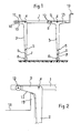
- - la figure 1 est une vue de côté d'un chariot ses béquilles déployées,
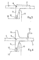
- - la figure 2, une vue en coupe au niveau des béquilles avant lors de la mise en place du chariot dans le coffre d'une voiture,
- - la figure 3, le rabattement des béquilles avant,
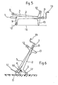
- - la figure 4, le rabattement des béquilles arrière,
- - la figure 5, l'immobilisation du chariot lors de sa mise en place dans le coffre d'un véhicule ou sur un sol quelconque,
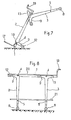
- - la figure 6, un mode d'utilisation en diable,
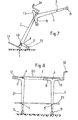
- - la figure 7, une variante d'utilisation en diable.
- Tel que représenté figure 1, le chariot comporte une assise 1 en forme de cadre généralement rectangulaire, sur ladite assise 1 sont articulées quatre béquilles 2 et 3 au moyen des axes 4, chaque béquille: 2 et 3 étant jumelée par l'axe d'articulation 4 et une traverse 5, en leur partie inférieure 6 sont maintenus de manière réglable en hauteur par tous moyens connus les supports 7 de roues fixes ou mobiles 8, au niveau de l'articulation 4 des béquilles 2 et 3 de part et d'autre de l'assise 1 ces dernières se prolongent par un bras 9 formant une équerre orientée vers l'avant du chariot, en l'extrémité 10 desdits bras sont maintenus de façon réglable en longueur par des moyens connus des supports 11 de roues 12, les béquilles 3 présentant outre les bras 9 un prolongement arrière 13 en équerre, les paires de béquilles 2 et 3 sont immobilisées en positions telles que déployée ou intermédiaire ou rabattue, par des moyens connus du type secteur à crans par exemple.
- Selon la représentation des figures 2 à 5 lorsque le chariot est utilisé en chariot de manutention tel que support de réceptacle en forme de panier ou table plane, pour son introduction dans le coffre d'un véhicule par exemple, une fois que la hauteur des roues 8 des béquilles 2 et 3 a été réglée par rapport à l'articulation 4 de manière à ce que le dessous de l'assise 1 puisse passer au-dessus du haut de la jupe 15 arrière du véhicule et notamment que la face 14 du bras 9 en pente prenne appui de par sa forme sur le haut de la
- La présente invention concerne un chariot de manutention pliable à multiples usages, tels que support de réceptacle, table mobile ou diable.
- On connaft par le brevet F 82 20358 un chariot de manutention pliable comportant un réceptacle dont les faces latérales sont repliables reposant sur une assise dotée de béquilles réglables en hauteur pouvant se rabattre sur et sous l'assise support de réceptacle, les béquilles étant dotées chacune en leur extrémité de roues fixes ou mobiles permettant le déplacement dudit chariot et des roues mobiles fixées sous l'assise permettant une fois les béquilles rabattues à tour de rôle son déplacement dans le coffre d'un véhicule par exemple, et/ou sur le sol, ce genre de réalisation bien que présentant certains avantages notamment au niveau des manutentions lors d'achats effectués dans les grandes ou petites surfaces par exemple a certains inconvénients tels que sa mise en place dans le coffre d'un véhicule et d'autre part est d'un usage restrictif.
- L'invention a pour but de pallier aux inconvénients précédemment exposés.
- L'invention a pour objet un chariot pliable de manutention comportant une assise prolongée par quatre béquilles repliables jumelées deux par deux réglables en hauteur, les béquilles avant et arrière étant repliables de l'avant à l'arrière de l'assise, elles sont dotées en leur extrémité de roues fixes ou mobiles, caractérisé en ce que chaque béquille au niveau de son articulation de part et d'autre de l'assise se prolonge vers l'avant de ladite assise par un bras en forme d'équerre, en extrémité de chacun desdits bras sont maintenus des supports réglables de roues fixes ou mobiles, les béquilles arrières présentant en plus un prolongement en équerre orienté vers l'arrière destiné à engendrer le blocage du chariot une fois que celui-ci repose au sol ou dans le véhicule.
- D'autres caractéristiques et avantages de l'invention ressortiront plus clairement de la description faite en regard des dessins joints donnés à titre d'exemple non limitatif, où :
- - la figure 1 est une vue de côté d'un chariot ses béquilles déployées,
- - la figure 2, une vue en coupe au niveau des béquilles avant lors de la mise en place du chariot dans le coffre d'une voiture,
- - la figure 3, le rabattement des béquilles avant,
- - la figure 4, le rabattement des béquilles arrière,
- - la figure 5, l'immobilisation du chariot lors de sa mise en place dans le coffre d'un véhicule ou sur un sol quelconque,
- - la figure 6, un mode d'utilisation en diable,
- - la figure 7, une variante d'utilisation en diable.
- Tel que représenté figure 1, le chariot comporte une assise 1 en forme de cadre généralement rectangulaire, sur ladite assise 1 sont articulées quatre béquilles 2 et 3 au moyen des axes 4, chaque béquille: 2 et 3 étant jumelée par l'axe d'articulation 4 et une traverse 5, en leur partie inférieure 6 sont maintenus de manière réglable en hauteur par tous moyens connus les supports 7 de roues fixes ou mobiles 8, au niveau de l'articulation 4 des béquilles 2 et 3 de part et d'autre de l'assise 1 ces dernières se prolongent par un bras 9 formant une équerre orientée vers l'avant du chariot, en l'extrémité 10 desdits bras sont maintenus de façon réglable en longueur par des moyens connus des supports 11 de roues 12, les béquilles 3 présentant outre les bras 9 un prolongement arrière 13 en équerre, les paires de béquilles 2 et 3 sont immobilisées en positions telles que déployée ou intermédiaire ou rabattue, par des moyens connus du type secteur à crans par exemple.
- Selon la représentation des figures 2 à 5 lorsque le chariot est utilisé en chariot de manutention tel que support de réceptacle en forme de panier ou table plane, pour son introduction dans le coffre d'un véhicule par exemple, une fois que la hauteur des roues 8 des béquilles 2 et 3 a été réglée par rapport à l'articulation 4 de manière à ce que le dessous de l'assise 1 puisse passer au-dessus du haut de la jupe 15 arrière du véhicule et notamment que la face 14 du bras 9 en pente prenne appui de par sa forme sur le haut de la jupe 15, par rotation et rabattement de la paire de béquilles 2 vers l'arrière du chassis 1, les roues 12 en bout de bras 9 prennent appui sur le plancher 16 du véhicule, la hauteur des roues 12 des bras 9 par rapport à l'articulation 4 ayant été au préalable réglée en fonction de la hauteur de la jupe 15 par rapport au plancher 16. Une fois les roues 12 des béquilles 2 en appui sur le plancher et les béquilles 2 immobilisées, il est aisé d'introduire le chariot à l'intérieur du coffre par simple poussée, jusqu'à la paire de béquilles 3, les bras 9 comme précédemment décrit prennant appui sur le haut de jupe 15 afin de rabattre la paire de béquilles 3 et immobiliser ces dernières lorsque les roues 12 sont en appui sur le plancher 16 du véhicule. Lorsque le chariot est mis en place dans le véhicule son immobilisation est engendrée par la prolongation de la rotation de la paire de béquilles 3 et ce jusqu'à ce que les bras 13 soient en appui sur le plancher 16 du véhicule, pour extraire le chariot du véhicule on procède de manière inverse de la description précédente.
- Selon un mode d'utilisation en diable représenté figure 6, sur l'axe d'articulation 4 des béquilles 2 alors que les béquilles 2 et 3 sont rabattues, est rapportée une plateforme amovible 17 présentant des crochets 18 s'emboitant sur ledit axe 4 assurant le maintien de ladite plateforme 17 support de matière à déplacer, le chariot étant déplacé grâce à l'appui des roues 12 des béquilles 2 sur le sol, la préhension du chariot étant effectuée soit par la poignée 19 tel que représenté figure 6 soit par la barre de jonction 5 des béquilles 3 lorsque ces dernières sont déployées et immobilisées à la position désirée.
- Selon le mode d'utilisation représenté figure 8 le chariot ayant ses béquilles 2 et 3 déployées reçoit sur son assise 1 un plateau supérieur 20 et les traverses 5 recoivent un plateau inférieur 21, lesdits plateaux 20 et 21 étant amovibles.
Claims (5)
Applications Claiming Priority (2)
| Application Number | Priority Date | Filing Date | Title |
|---|---|---|---|
| FR8513786A FR2587290B1 (fr) | 1985-09-16 | 1985-09-16 | Chariot de manutention pliable a usages multiples |
| FR8513786 | 1985-09-16 |
Publications (2)
| Publication Number | Publication Date |
|---|---|
| EP0220128A1 true EP0220128A1 (fr) | 1987-04-29 |
| EP0220128B1 EP0220128B1 (fr) | 1990-07-04 |
Family
ID=9322992
Family Applications (1)
| Application Number | Title | Priority Date | Filing Date |
|---|---|---|---|
| EP19860450019 Expired - Lifetime EP0220128B1 (fr) | 1985-09-16 | 1986-09-16 | Chariot de manutention pliable à usages multiples |
Country Status (3)
| Country | Link |
|---|---|
| EP (1) | EP0220128B1 (fr) |
| DE (1) | DE3672445D1 (fr) |
| FR (1) | FR2587290B1 (fr) |
Cited By (1)
| Publication number | Priority date | Publication date | Assignee | Title |
|---|---|---|---|---|
| DE29817051U1 (de) * | 1998-09-23 | 2000-02-10 | Lindenberg, Kai, 64285 Darmstadt | In Kraftfahrzeug transportierbarer, klappbarer Handschiebekarren zum Transportieren von Lasten |
Families Citing this family (1)
| Publication number | Priority date | Publication date | Assignee | Title |
|---|---|---|---|---|
| US4953878A (en) * | 1988-10-31 | 1990-09-04 | Sbragia Frank J | Collapsible cart |
Citations (5)
| Publication number | Priority date | Publication date | Assignee | Title |
|---|---|---|---|---|
| DE2033855A1 (de) * | 1969-10-02 | 1971-04-15 | Weil, Burt, Cmcinnati Ohio (V St A) | Zusammenlegbarer Handwagen |
| DE2635238A1 (de) * | 1976-08-05 | 1978-03-16 | Karl Fels | Wagen der in zwei ebenen gefahren werden kann |
| FR2366971A1 (fr) * | 1976-10-07 | 1978-05-05 | Eicher Josef | Chariot propre a etre charge dans le coffre d'une voiture |
| DE2651039A1 (de) * | 1976-11-09 | 1978-05-18 | Karl Fels | Wagen zum transport von gegenstaenden |
| DE2732757A1 (de) * | 1977-07-20 | 1979-02-01 | Karl Fels | Wagen zum transport von gegenstaenden |
-
1985
- 1985-09-16 FR FR8513786A patent/FR2587290B1/fr not_active Expired
-
1986
- 1986-09-16 EP EP19860450019 patent/EP0220128B1/fr not_active Expired - Lifetime
- 1986-09-16 DE DE8686450019T patent/DE3672445D1/de not_active Expired - Fee Related
Patent Citations (5)
| Publication number | Priority date | Publication date | Assignee | Title |
|---|---|---|---|---|
| DE2033855A1 (de) * | 1969-10-02 | 1971-04-15 | Weil, Burt, Cmcinnati Ohio (V St A) | Zusammenlegbarer Handwagen |
| DE2635238A1 (de) * | 1976-08-05 | 1978-03-16 | Karl Fels | Wagen der in zwei ebenen gefahren werden kann |
| FR2366971A1 (fr) * | 1976-10-07 | 1978-05-05 | Eicher Josef | Chariot propre a etre charge dans le coffre d'une voiture |
| DE2651039A1 (de) * | 1976-11-09 | 1978-05-18 | Karl Fels | Wagen zum transport von gegenstaenden |
| DE2732757A1 (de) * | 1977-07-20 | 1979-02-01 | Karl Fels | Wagen zum transport von gegenstaenden |
Cited By (1)
| Publication number | Priority date | Publication date | Assignee | Title |
|---|---|---|---|---|
| DE29817051U1 (de) * | 1998-09-23 | 2000-02-10 | Lindenberg, Kai, 64285 Darmstadt | In Kraftfahrzeug transportierbarer, klappbarer Handschiebekarren zum Transportieren von Lasten |
Also Published As
| Publication number | Publication date |
|---|---|
| DE3672445D1 (de) | 1990-08-09 |
| FR2587290B1 (fr) | 1988-02-05 |
| FR2587290A1 (fr) | 1987-03-20 |
| EP0220128B1 (fr) | 1990-07-04 |
Similar Documents
| Publication | Publication Date | Title |
|---|---|---|
| US3913762A (en) | Combination hand and lift cart | |
| US5772222A (en) | Convertible vehicle | |
| BE1014630A3 (fr) | Engin de manutention de type diable. | |
| EP0442780B1 (fr) | Palette de transport de vitrages | |
| EP2590849B1 (fr) | Chariot d'achats | |
| EP0204637B1 (fr) | Etabli mobile à moyens de manoeuvre exclusivement mécaniques | |
| EP0220128B1 (fr) | Chariot de manutention pliable à usages multiples | |
| EP0146557B1 (fr) | Dispositif de renversement pour vehicules | |
| EP0799789B1 (fr) | Dispositif de solidarisation d'un chariot de manutention à un camion, châssis de support et camion correspondants | |
| FR2648099A1 (fr) | Chariot de manutention a plateau elevateur basculant | |
| FR2544681A1 (fr) | Brouette a benne basculante | |
| FR2618400A1 (fr) | Chariot destine au transport d'articles divers | |
| FR2496034A1 (fr) | Nouvel appareil de manutention du genre diable | |
| FR2522597A1 (fr) | Appareil pour la manutention de charges | |
| FR2537077A1 (fr) | Chariot de manutention | |
| FR2620994A1 (fr) | Chariot destine au transport de marchandises diverses | |
| EP0749921B1 (fr) | Pupitre destiné au transport, au stockage, à la manutention et à la pose d'éléments verticaux et plats | |
| FR2781745A1 (fr) | Chariot de manutention a jambages repliables | |
| EP3653170B1 (fr) | Table elevatrice | |
| BE1012085A6 (fr) | Chariot de transport du type "diable". | |
| FR2784022A1 (fr) | Ensemble utilitaire pour personnes a mobilite reduite | |
| FR2633567A1 (fr) | Dispositif de manutention d'une charge portee par un vehicule | |
| FR2545405A1 (fr) | Dispositif support elevateur pour vehicule a deux roues | |
| FR2762977A1 (fr) | Table a rallonges | |
| FR2669588A1 (fr) | Dispositif support de chariot elevateur embarque. |
Legal Events
| Date | Code | Title | Description |
|---|---|---|---|
| PUAI | Public reference made under article 153(3) epc to a published international application that has entered the european phase |
Free format text: ORIGINAL CODE: 0009012 |
|
| AK | Designated contracting states |
Kind code of ref document: A1 Designated state(s): CH DE GB IT LI NL |
|
| 17P | Request for examination filed |
Effective date: 19871028 |
|
| 17Q | First examination report despatched |
Effective date: 19880908 |
|
| GRAA | (expected) grant |
Free format text: ORIGINAL CODE: 0009210 |
|
| AK | Designated contracting states |
Kind code of ref document: B1 Designated state(s): CH DE GB IT LI NL |
|
| REF | Corresponds to: |
Ref document number: 3672445 Country of ref document: DE Date of ref document: 19900809 |
|
| ITF | It: translation for a ep patent filed | ||
| ITTA | It: last paid annual fee | ||
| GBT | Gb: translation of ep patent filed (gb section 77(6)(a)/1977) | ||
| PLBE | No opposition filed within time limit |
Free format text: ORIGINAL CODE: 0009261 |
|
| STAA | Information on the status of an ep patent application or granted ep patent |
Free format text: STATUS: NO OPPOSITION FILED WITHIN TIME LIMIT |
|
| 26N | No opposition filed | ||
| PGFP | Annual fee paid to national office [announced via postgrant information from national office to epo] |
Ref country code: NL Payment date: 19910930 Year of fee payment: 6 |
|
| PGFP | Annual fee paid to national office [announced via postgrant information from national office to epo] |
Ref country code: CH Payment date: 19911007 Year of fee payment: 6 |
|
| PGFP | Annual fee paid to national office [announced via postgrant information from national office to epo] |
Ref country code: DE Payment date: 19911129 Year of fee payment: 6 |
|
| PGFP | Annual fee paid to national office [announced via postgrant information from national office to epo] |
Ref country code: GB Payment date: 19920316 Year of fee payment: 6 |
|
| PG25 | Lapsed in a contracting state [announced via postgrant information from national office to epo] |
Ref country code: GB Effective date: 19920916 |
|
| PG25 | Lapsed in a contracting state [announced via postgrant information from national office to epo] |
Ref country code: LI Effective date: 19920930 Ref country code: CH Effective date: 19920930 |
|
| PG25 | Lapsed in a contracting state [announced via postgrant information from national office to epo] |
Ref country code: NL Effective date: 19930401 |
|
| GBPC | Gb: european patent ceased through non-payment of renewal fee |
Effective date: 19920916 |
|
| NLV4 | Nl: lapsed or anulled due to non-payment of the annual fee | ||
| REG | Reference to a national code |
Ref country code: CH Ref legal event code: PL |
|
| PG25 | Lapsed in a contracting state [announced via postgrant information from national office to epo] |
Ref country code: DE Effective date: 19930602 |
|
| PG25 | Lapsed in a contracting state [announced via postgrant information from national office to epo] |
Ref country code: IT Free format text: LAPSE BECAUSE OF NON-PAYMENT OF DUE FEES;WARNING: LAPSES OF ITALIAN PATENTS WITH EFFECTIVE DATE BEFORE 2007 MAY HAVE OCCURRED AT ANY TIME BEFORE 2007. THE CORRECT EFFECTIVE DATE MAY BE DIFFERENT FROM THE ONE RECORDED. Effective date: 20050916 |