EP0219980A1 - Vorrichtung zum Öffnen und Schliessen einer Verschlussvorrichtung einer Plattenkassette - Google Patents
Vorrichtung zum Öffnen und Schliessen einer Verschlussvorrichtung einer Plattenkassette Download PDFInfo
- Publication number
- EP0219980A1 EP0219980A1 EP86307281A EP86307281A EP0219980A1 EP 0219980 A1 EP0219980 A1 EP 0219980A1 EP 86307281 A EP86307281 A EP 86307281A EP 86307281 A EP86307281 A EP 86307281A EP 0219980 A1 EP0219980 A1 EP 0219980A1
- Authority
- EP
- European Patent Office
- Prior art keywords
- opening
- shutter member
- disc
- disc cartridge
- closing
- Prior art date
- Legal status (The legal status is an assumption and is not a legal conclusion. Google has not performed a legal analysis and makes no representation as to the accuracy of the status listed.)
- Granted
Links
- 238000003780 insertion Methods 0.000 claims abstract description 26
- 230000037431 insertion Effects 0.000 claims abstract description 26
- 230000003287 optical effect Effects 0.000 description 15
- 230000001105 regulatory effect Effects 0.000 description 11
- 230000002401 inhibitory effect Effects 0.000 description 3
- 230000000694 effects Effects 0.000 description 2
- 229920002994 synthetic fiber Polymers 0.000 description 2
- 230000008021 deposition Effects 0.000 description 1
- 239000000428 dust Substances 0.000 description 1
- 230000005764 inhibitory process Effects 0.000 description 1
- 230000013011 mating Effects 0.000 description 1
- 238000000465 moulding Methods 0.000 description 1
- 230000000717 retained effect Effects 0.000 description 1
- 229910001220 stainless steel Inorganic materials 0.000 description 1
- 239000010935 stainless steel Substances 0.000 description 1
Images


Classifications
-
- G—PHYSICS
- G11—INFORMATION STORAGE
- G11B—INFORMATION STORAGE BASED ON RELATIVE MOVEMENT BETWEEN RECORD CARRIER AND TRANSDUCER
- G11B17/00—Guiding record carriers not specifically of filamentary or web form, or of supports therefor
- G11B17/02—Details
- G11B17/04—Feeding or guiding single record carrier to or from transducer unit
- G11B17/041—Feeding or guiding single record carrier to or from transducer unit specially adapted for discs contained within cartridges
- G11B17/043—Direct insertion, i.e. without external loading means
- G11B17/0436—Direct insertion, i.e. without external loading means with opening mechanism of the cartridge shutter
-
- G—PHYSICS
- G11—INFORMATION STORAGE
- G11B—INFORMATION STORAGE BASED ON RELATIVE MOVEMENT BETWEEN RECORD CARRIER AND TRANSDUCER
- G11B23/00—Record carriers not specific to the method of recording or reproducing; Accessories, e.g. containers, specially adapted for co-operation with the recording or reproducing apparatus ; Intermediate mediums; Apparatus or processes specially adapted for their manufacture
- G11B23/02—Containers; Storing means both adapted to cooperate with the recording or reproducing means
- G11B23/03—Containers for flat record carriers
- G11B23/0301—Details
- G11B23/0308—Shutters
Definitions
- This invention relates to devices for opening and closing shutter members provided in disc cartridges, such devices being used in conjunction with signal recording and/or reproducing apparatus. More particularly, the invention relates to such devices for opening and closing a shutter member mounted movably to a disc cartridge for opening and closing signal read and/or write apertures in upper and lower surfaces of the disc cartridge, the disc cartridge containing a disc such as an optical or optomagnetic disc.
- signal recording and/or reproducing apparatus is taken to include a magnetic, an optomagnetic or an optical apparatus in the sense that it makes use of a magnetic, an optomagnetic or an optical disc as the signal recording medium.
- optical or magnetic discs used as signal recording media of signal recording and/or reproducing apparatus it has been proposed for optical or magnetic discs used as signal recording media of signal recording and/or reproducing apparatus to be contained in a disc cartridge for protecting their signal recording surfaces, and to be mounted in the recording and/or reproducing apparatus while they are contained in this manner in the disc cartridge.
- the disc cartridge containing the disc is provided on its upper and lower surfaces with apertures to be confronted by a pickup unit of the apparatus, such as an optical pickup unit designed to effect signal reading or signal writing operations when the disc cartridge is inserted into the recording and/or reproducing apparatus.
- a device for opening and closing the shutter member has to be provided in a recording and/or reproducing apparatus, such as a disc player, making use of the above-
- a device for opening and closing a shutter member provided in a disc cartridge insertable into signal recording and/or reproducing apparatus which uses a disc as a signal recording medium
- the disc cartridge including the disc in a cartridge housing, said cartridge housing having signal read and/or write apertures in an upper surface and a lower surface thereof, said shutter member being mounted so as to partially cover a front wall, an upper wall and a lower wall of said cartridge housing and being arranged to open and close said apertures, said shutter member having an engaging opening extending in said front wall and said lower wall
- said device comprises a pair of shutter member opening and closing members provided in the signal recording and/or reproducing apparatus so as to engage said disc cartridge during insertion thereof, said members having engaging portions for selectively engaging in said engaging opening of said shutter member and for being pivoted by thrust from said disc cartridge during insertion, said shutter member opening and closing members being so arranged that portions of said opening and closing members contact each other to inhibit full insertion of said disc cartridge when the disc cartridge is being inserted from its rear side opposite to its
- a preferred embodiment of the invention provides a system for positively inhibiting incorrect insertion of the disc cartridge, preventing incorrect insertion of the disc cartridge without providing a separate dedicated device by imparting an incorrect insertion inhibit function to the opening and closing device, thereby avoiding complicating the system.
- the preferred embodiment is capable of protecting the disc cartridge by preventing incorrect insertion thereof as well as protecting the pickup unit of the recording and/or reproducing apparatus by preventing incorrect operation of the pickup unit.
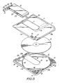
- a disc cartridge 1, to which a shutter opening and closing device according to a preferred embodiment of the present invention may be applied, will be described with reference to Figures 2 to 5.
- the disc cartridge 1 comprises a cartridge casing or housing 5 formed by an upper half 2 and a lower half 3 that are abutted and secured to each other by a number of screws 4, a disc such as an optomagnetic disc 6 rotatably contained in the cartridge housing 5, and a shutter member 9.
- the upper and lower halves 2 and 3 may be formed by moulding of synthetic material into the shape of flat square plates.
- the shutter member 9 is slidably mounted to the cartridge housing 5 and arranged to open or close window sections 7 and 8 intended for signal reading or writing and which are formed respectively in the upper half 2 and the lower half 3 making up the cartridge housing 5.
- an optical pickup unit faces these window sections 7 and 8, the pickup unit being designed for writing or reading information signals to or from the disc 6.
- the upper half 2 and the lower half 3 making up the cartridge housing 5 are configured symmetrically to each other, except that writing protection members 10 for inhibiting writing to the disc 6 are disposed at corresponding positions so that, then the upper and lower halves 2,3 are abutted to and engaged with each other, the protection member 10 on each half is disposed at the opposite position to that on the other half.
- the upper half 2 and the lower half 3 are so constructed that, when they are abutted and connected to each other, there is defined therebetween a space of a size and shape sufficient to accommodate rotatably the disc 6.
- the window sections 7,8 are confronted by the optical pickup unit and used for signal reading and writing as indicated above.
- the window sections 7,8 are formed as approximately rectangular apertures extending from the centre of the upper half 2 and the lower half 3 to the front side wall member 12 to which the shutter member 9 is mounted.
- a plurality of arcuate rib sections 16 are formed on the inner side of each of the upper half 2 and the lower half 3 and on a circumference of a circle that is centred about the apertures 14,15 and that is slightly larger than the outer perimeter of the disc 6. When abutted to one another, these rib sections 16 cooperate with one another to define wall sections delimiting the disc-containing section while regulating the horizontal position of the disc 6.
- reference holes 17,18 On both side corners of the rear side wall member 13 of the upper half 2 and the lower half 3 opposite to the front wall member 12, there are formed reference holes 17,18, that may be engaged by mating positioning pins provided in the recording and/or reproducing apparatus, so as to set the reference mounting position thereof with respect to the disc cartridge 1.
- the upper half 2 and the lower half 3 thus provided with the female threaded sections 19 are connected together by screws 4 engaged in the female threaded sections 19 so as to form the cartridge housing 5 rotatably containing the disc 6.
- slide guide slots 20 for sliding and guiding the shutter member 9 arranged to open and close the window sections 7 and 8.
- the shutter member 9 may be formed by a metallic plate such as a stainless steel plate in the form of a letter U in cross-section. It is slidably mounted by virtue of the slide guide slots 20 provided in the upper and lower surfaces of the cartridges housing 5 in opposition to each other.
- the shutter member 9 is formed by a front web section 21 from the upper and lower sides of which an upper plate or upper shutter plate 22 and a lower plate or lower shutter plate 23 are integrally formed and which extend in parallel to each other. These plates 22,23 are of a size and shape sufficient to cover the window sections 7,8, and apertures 14 and 15 simultaneously.
- the front web section 21 and adjacent sections of the upper shutter plate 22 and the lower shutter plate 23 of the shutter member 9 cooperate with one another to define a slide guide section 24 for the cartridge housing 5.
- the slide guide section 24 is extended from one side of each of the upper and lower shutter plates 22,23 along the slide guide slot 20.
- the shutter member 9 is approximately in the form of a letter U when seen in side view.
- the slide guide section 24 is formed with a rib 26 by drawing between the guide tabs 25,25 in order to prevent flexure of the slide guide section 24 in a direction normal to the direction of the thickness of the disc cartridge 1 otherwise caused as a result of setting the width of the section 24 so as to be longer than that of the upper or lower shutter plates 22,23.
- the shutter member 9 is formed, towards one side of the front wall section 21 thereof, with a tab 28 to be engaged by a locking member 27 of the cartridge housing 5 when the shutter member 9 is at a first position closing the window sections 7,8.
- the shutter member 9 is also formed with an opening 29 extending in the front web section 21 and in the lower shutter plate 23 so as to be selectively engaged by protuberant shutter member opening and closing pins implanted at the foremost part of shutter opening and closing arms in turn provided in the recording and/or reproducing apparatus, as will be described.
- the opening 29 is an L-shaped slot extending in the front web section 21 and in the lower shutter plate 23.
- the opening 29 is engaged the aforementioned shutter member opening and closing pin of the shutter member opening and closing arm in a direction normal to the direction of the thickness of the disc cartridge 1.
- the opening 29 is provided at a position which, when the shutter member 9 is in the first position closing the window sections 7,8 and apertures 14 and 15, is displaced from the widthwise centre of the cartridge housing 5 and in register with a flat section 27c towards the free end of the locking member 27 provided towards one corner of the front side of the cartridge housing 5.
- the shutter member 9 is formed with a guide section 30 which is bent inwardly such that, when the disc cartridge 1 is inserted into the recording and/or reproducing device, the opening and closing pin not used for opening or closing the shutter member and not engaged in the opening 29 may easily be deviated as it rides on the front web section 21.
- the thus-constructed shutter member 9 is mounted so as to overlie the respective upper surfaces and the front wall member 12 of the upper half 2 and the lower half 3 of the cartridge housing 5 for sliding along the slide guide section 24, with the guide tabs 25 being engaged and guided along the slide guide slot 20 in the cartridge housing 5.
- the cartridge housing 5 is formed at the front wall member 12 thereof with a groove 31 which is formed by partially recessing the front wall section 12 towards the interior of the cartridge housing 5 itself and in which there are slidably disposed the tab 28 and the projecting shutter member opening and closing pins of the shutter member opening and closing arms (to be described later).
- the portion of the lower half 3 defining the groove 31 is removed for delimiting a cut-out 32 in which the projecting opening and closing pins of the opening and closing arms (to be described later) intrude and slide.
- a recess 33 for delimiting the extent of sliding movement of the shutter member 9, inclusive of the peripheries of the window sections 7,8 and apertures 14,15.
- the shutter member 9 is movable between the first position of closing the window sections 7,8 and apertures 14,15 and the second position of opening these window sections and apertures.
- the locking member 27 (typically moulded from synthetic material) having a locking recess 35 for locking the shutter member 9.
- this recess 35 is engaged the tab 28 for locking the shutter member 9 when the shutter member 9 is in the first position of closing the window sections 7,8 and apertures 14 and 15, as shown in Figure 4.
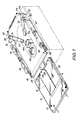
- the recording and/or reproducing apparatus includes a disc mounting section or unit 41 which is provided with a set of heightwise positioning pins (not shown) for engaging in the reference apertures 17 and 18 in the disc cartridge 1 for heightwise positioning of the cartridge 1 as well as another set of pins (also not shown) for supporting the surface of the disc cartridge 1. It is by means of this disc mounting section 41 that the disc cartridge 1 is mounted to the signal recording and/or reproducing apparatus with positioning in the horizontal and heightwise directions.
- the disc mounting section 41 is provided with a disc rotation and drive unit 43 provided in turn with a disc table 42 for rotatably driving the disc 6 in the disc cartridge 6, and a chucking device (not shown) for clamping the disc 6 to the disc table 42 so that the disc 6 may be rotated in synchronism with the disc table 42.
- the apparatus also includes the aforementioned optical pickup unit 44 in facing relation to the lower side of the disc cartridge 1 and mounted to the disc mounting unit 41.
- the pickup unit 44 is movable between the inner and outer peripheries of the disc 6 for writing or reading information signals to or from the signal recording surface of the disc 6.
- the disc mounting section 41 in the recording and/or reproducing apparatus is provided with a frame 45 arranged to support the disc cartridge 1 which is inserted through the disc inserting and removal opening in the outer casing of the recording and/or reproducing apparatus.
- the supporting frame 45 is vertically movably supported on a chassis provided with the aforementioned disc rotation and drive unit 43 and the pickup unit 44.
- the supporting frame 45 is in the form of a flat square plate having a width approximately equal to the width of the disc cartridge 1.
- a front side of the supporting frame 45 is designed with an opening 48 for reception of the disc cartridge 1.
- the supporting frame 45 is supported vertically movably on the chassis so that, during insertion and removal of the disc cartridge 1, the opening 48 is in a facing relation to the disc insertion and removal opening and so that, during use of the disc cartridge 1, the supporting frame 45 is in the lower position in which it is supported and positioned by the sets of the supporting and positioning pins.
- first and second shutter member opening and closing arms 51,52 are provided in opposition to the insertion direction of the disc cartridge 1.
- These shutter member opening and closing arms 51 and 52 are provided at the proximate ends thereof with tubular sections 55,56 positioned over supporting shafts 53,54 mounted on the inner corners of the supporting frame 45.
- first and second shutter member opening and closing pins 57,58 are provided at the distal ends of the shutter member opening and closing arms 51,52.
- the length of the shutter member opening and closing arm 51 between the tubular section 5 and the pin 57 is arranged to be equal to that of the arm 52 between the tubular section 56 and the pin 58.
- the supporting shafts 53,54 are implanted symmetrically in the widthwise direction with the rotational centre of the disc rotation drive unit 43 as centre, with the rotational centre being on the centreline along which the disc cartridge 1 is inserted into the frame 45.
- the first and second shutter member opening and closing arms 51,52 are pivotally mounted by the supporting shafts 53,54 passing through the tubular sections 55,56 such that the first and second shutter member opening and closing pins 57,58 project in mutually opposite directions. Since the first and second shutter member opening and closing arms 51,52 are of the same length and mounted by the supporting shafts 53,54 that are symmetrical with respect to the centreline along which the disc cartridge 1 is inserted, the arms 51,52 are mounted symmetrically with the centre of insertion of the disc cartridge 1 as centre.
- the length of the first and second shutter member opening and closing arms 51,52 is selected so that, when they are pivoted about the supporting shafts 53,54 in a direction so as to approach each other, the trajectories of the first and second shutter member opening and closing pins 57,58 implanted on the distal ends of the arms 51,52 strike each other in the course of pivoting of the arms 51,52.
- the first and second shutter member opening and closing arms 51,52 are also mounted to the supporting shafts 53,54 with a heightwise gap or spacing larger than the thickness of the disc cartridge 1, in order that the respective one of the first and the second shutter member opening and closing pins 57,58 will be engaged in the opening 29 of the shutter member 9 at the time of insertion of the disc cartridge 1 without the opening and closing arms 51,52 abutting on the disc cartridge 1, as shown in Figure 8.
- the second shutter member opening and closing pin 58 is longer than the first shutter opening and closing pin 57, as shown in Figure 7, such that the pins 57,58 impinge on each other in the heightwise direction thereof.
- first and second pins 57,58 may be of the same height, since it suffices that the pins 57,58 overlap in the heightwise direction.
- the first and second shutter member opening and closing arms 51,52 are biased so as to pivot in a direction away from each other or towards the outer sides of the frames 45 by a tension spring 60 retained by shafts 59 projecting from the tubular sections 55,56 in a direction substantially at right angles with the shutter member opening and closing arms 51,52.
- the rotational biasing position of the first shutter member opening and closing arm 51 is regulated by an arm regulating member 61 such that, when the disc cartridge 1 is introduced into the recording and/or reproducing apparatus with the upper surface of the disc cartridge 1 directed upwards and the first signal recording surface of the disc 6 facing the optical recording unit 44, the first pin 57 on the distal end of the arm 51 is positioned facing the opening 29 of the shutter member 9.
- the rotational biasing position of the second shutter member opening and closing arm 52 is regulated by a second arm regulating member 62 such that, when the disc cartridge 1 is introduced into the recording and/or reproducing apparatus with the lower surface of the disc cartridge 1 directed upwards and the second signal recording surface of the disc 6 facing the optical recording unit 44, the second pin 58 on the distal end of the arm 52 is positioned facing the opening 29 of the shutter member 9.
- a pair of regulating projections 63 for regulating the limit position of insertion of the disc cartridge 1.
- the disc cartridge 1 is inserted through the disc inserting and removal opening with the upper surface of the disc cartridge 1 facing upwards and with the first signal recording surface of the disc 6 facing the optical pickup unit 44.
- the first shutter member opening and closing pin 57 at the distal end of the first shutter member opening and closing arm 51 is engaged at this time in the opening 29 in the shutter member 9.
- the first shutter member opening and closing pin 57 thrusts the flat section 27c of the locking member 27 of the cartridge housing 5 so as to displace the locking member 27 and disengage the tab 28 from the cut-out 35 of the locking member 27, thereby to permit sliding movement of the shutter member 9.
- the second shutter member opening and closing pin 58 at the distal end of the second shutter member opening and closing arm 52 rides on the inclined guide section 30 formed at the other end of the shutter member 9 such that the arm 52 is pivoted in the direction indicated by an arrow mark A in Figure 6 against the urging of the tension spring 60 in advance of pivoting of the first arm 51.
- the second arm 52 is pivoted in advance of pivoting of the first arm 51 by a time interval necessary for the first pin 57 on the first shutter member opening and closing arm 51 to be engaged in the opening 29.
- the first shutter member opening and closing arm 51 is also thrust by the disc cartridge 1 so that the arm 51 starts to pivot against urging of the tension spring 60 in the direction indicated by an arrow mark B in Figure 6.
- the first shutter member opening and closing pin 57 is engaged at this time in the opening 29 of the shutter member 9, and the shutter member 9 is unlocked, such that the above-described pivoting of the first shutter member opening and closing arm 51 causes the shutter member 9 to be moved from the first position of closing the apertures 7, 8, 14 and 15 towards the second position of opening these apertures 7, 8, 14 and 15.
- the shutter member 9 is completely shifted by the first arm 51 to the second position of opening the apertures 7, 8, 14 and 15.
- the second shutter member opening and closing arm 52 pivoted in advance of the first arm 51, is pivoted with the second shutter member opening and closing pin 58 thereof sliding on the front wall section 21 of the shutter member 9, starting from the inclined guide section 30.
- the first and second shutter member opening and closing arms 51,52 are pivoted with a relative shift in the timing of the initial movement thereof and thus without the first and second shutter member opening and closing pins 57,58 striking each other, in other words their movement is staggered.
- the shutter member opening operation is otherwise the same as that described hereinabove with the first surface of the disc 6 facing the optical pickup unit 44, except that the operation of the first arm 51 and that of the second arm 52 are interchanged. Therefore, a detailed description will be omitted for simplicity.
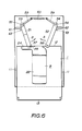
- first and second shutter member opening and closing pins 57,58 abut on each other at the point of intersection of the rotational trajectories of the first and second arms 51,52, as shown in Figure 10, so as to inhibit further pivoting of the first and second shutter member opening and closing arms 51,52 and hence any further incorrect insertion of the disc cartridge 1.
- the shutter member opening and closing arms provided in the way of insertion of the disc cartridge, and having projections for selective engagement in the opening in the shutter member of the disc cartridge, are pivoted to cause the projections to strike each other such that further incorrect insertion of the disc cartridge is prevented through inhibition of further pivoting of the shutter member opening and closing arms, and hence any further insertion of the disc cartridge cannot take place.
- the above-described system for inhibiting incorrect insertion of the disc cartridge is included in the opening and closing device for the shutter member so that a simplified system is provided for preventing the disc cartridge from being inserted incorrectly.
- the disc cartridge is prevented in this manner from being introduced incorrectly, it is possible to protect the disc cartridge and the pickup unit of the recording and/or reproducing apparatus against incorrect operation of the unit, while also protecting the disc rotation drive unit as well as the disc chucking unit.
Priority Applications (1)
| Application Number | Priority Date | Filing Date | Title |
|---|---|---|---|
| AT86307281T ATE61145T1 (de) | 1985-09-23 | 1986-09-22 | Vorrichtung zum oeffnen und schliessen einer verschlussvorrichtung einer plattenkassette. |
Applications Claiming Priority (2)
| Application Number | Priority Date | Filing Date | Title |
|---|---|---|---|
| JP60209537A JPH0640413B2 (ja) | 1985-09-23 | 1985-09-23 | デイスクカ−トリツジのシヤツタ開閉機構 |
| JP209537/85 | 1985-09-23 |
Publications (2)
| Publication Number | Publication Date |
|---|---|
| EP0219980A1 true EP0219980A1 (de) | 1987-04-29 |
| EP0219980B1 EP0219980B1 (de) | 1991-02-27 |
Family
ID=16574444
Family Applications (1)
| Application Number | Title | Priority Date | Filing Date |
|---|---|---|---|
| EP86307281A Expired - Lifetime EP0219980B1 (de) | 1985-09-23 | 1986-09-22 | Vorrichtung zum Öffnen und Schliessen einer Verschlussvorrichtung einer Plattenkassette |
Country Status (7)
| Country | Link |
|---|---|
| US (1) | US4688206A (de) |
| EP (1) | EP0219980B1 (de) |
| JP (1) | JPH0640413B2 (de) |
| KR (1) | KR960005123B1 (de) |
| AT (1) | ATE61145T1 (de) |
| CA (1) | CA1264197A (de) |
| DE (1) | DE3677697D1 (de) |
Cited By (11)
| Publication number | Priority date | Publication date | Assignee | Title |
|---|---|---|---|---|
| GB2208029A (en) * | 1987-08-13 | 1989-02-15 | Nintendo Co Ltd | Data recording device with I.D. symbol |
| GB2208330A (en) * | 1987-07-27 | 1989-03-22 | Hitachi Ltd | An optical disc cartridge and a mechanism for preventing an incorrect insertion of a cartridge |
| US4860128A (en) * | 1985-04-24 | 1989-08-22 | Nintendo Co., Ltd. | Recordable data device having identification symbols formed thereon and cooperating data processing system having registering symbols |
| US4865321A (en) * | 1985-10-04 | 1989-09-12 | Nintendo Company Limited | Memory cartridge and information processor unit using such cartridge |
| EP0335461A1 (de) * | 1988-03-31 | 1989-10-04 | Koninklijke Philips Electronics N.V. | Kassette |
| GB2227874A (en) * | 1988-11-22 | 1990-08-08 | Lam Philip Y T | A video and/or audio cassette assembly |
| EP0407140A2 (de) * | 1989-07-05 | 1991-01-09 | Hitachi Maxell Ltd. | Plattenantriebsgerät |
| US5016236A (en) * | 1988-09-30 | 1991-05-14 | Goldstar Co., Ltd. | Disc loading apparatus for a vertical type compact disc player |
| GB2270194A (en) * | 1992-08-24 | 1994-03-02 | Tdk Corp | A sliding shutter for a cartridge e.g. a diskette or dat cassette |
| EP0657882A2 (de) * | 1993-11-30 | 1995-06-14 | Kabushiki Kaisha Toshiba | Gerät für Plattenkassette |
| EP0962934A2 (de) * | 1997-12-16 | 1999-12-08 | Matsushita Electric Industrial Co., Ltd. | Plattenkassette |
Families Citing this family (43)
| Publication number | Priority date | Publication date | Assignee | Title |
|---|---|---|---|---|
| US4740949A (en) * | 1985-08-16 | 1988-04-26 | Laser Magnetic Storage International Company | Laser access apparatus for optical disk drive |
| JPS6253572A (ja) * | 1985-09-03 | 1987-03-09 | Nec Corp | フアクシミリ装置 |
| US4823214A (en) * | 1985-09-19 | 1989-04-18 | Laser Magnetic Storage International Company | Disk drive for cartridge disks |
| US4791511A (en) * | 1985-09-19 | 1988-12-13 | Laser Magnetic Storage International Company | Disk cartridge with slide door engageable in either of two orientations |
| USRE34161E (en) | 1985-10-04 | 1993-01-12 | Nintendo Company Limited | Memory cartridge and information processor unit using such cartridge |
| JPH0740422B2 (ja) * | 1985-10-07 | 1995-05-01 | 日立マクセル株式会社 | デイスクカ−トリツジ |
| JPS6273367U (de) * | 1985-10-29 | 1987-05-11 | ||
| JPS6290448U (de) * | 1985-11-22 | 1987-06-10 | ||
| JPH077556B2 (ja) * | 1986-06-13 | 1995-01-30 | 株式会社東芝 | 情報処理装置 |
| JPS6361484A (ja) * | 1986-09-01 | 1988-03-17 | Toshiba Corp | 情報記憶媒体用カ−トリツジ |
| US4746013A (en) * | 1986-09-16 | 1988-05-24 | Sony Corporation | Disc cartridge with releasable locking means |
| US4945530A (en) * | 1986-11-14 | 1990-07-31 | Opticord, Inc. | Cartridge for optical data discs |
| US4908817A (en) * | 1986-11-14 | 1990-03-13 | Opticord, Inc. | Cartridge for optical data discs |
| JP2530140B2 (ja) * | 1987-01-30 | 1996-09-04 | 株式会社リコー | デイスクロ−デイング機構 |
| US4779159A (en) * | 1987-06-09 | 1988-10-18 | Verbatim Corporation | Shutter latch mechanism for a disk cartridge |
| US4858050A (en) * | 1987-06-09 | 1989-08-15 | Verbatim Corp. | Structurally rigid disk cartridge adaptable to eliminating relative axial cartridge and/or transducer head loading/unloading movement |
| JPH0621078Y2 (ja) * | 1987-08-06 | 1994-06-01 | パイオニア株式会社 | カ−トリッジ収納ディスク演奏装置 |
| JPH0510275Y2 (de) * | 1987-12-09 | 1993-03-12 | ||
| US5195084A (en) * | 1988-03-07 | 1993-03-16 | Tdk Corporation | Disc cartridge |
| JP2521799Y2 (ja) * | 1988-06-20 | 1997-01-08 | 日立マクセル株式会社 | デイスクカートリツジ |
| JPH0739106Y2 (ja) * | 1988-06-29 | 1995-09-06 | 大日本印刷株式会社 | 両面用光ディスクカートリッジのシャッタ |
| NL8802185A (nl) * | 1988-09-05 | 1990-04-02 | Philips Nv | Schijfcassette. |
| JPH0828096B2 (ja) * | 1988-09-29 | 1996-03-21 | 松下電器産業株式会社 | 磁気ディスクカセット |
| JPH02110069U (de) * | 1989-02-13 | 1990-09-03 | ||
| JPH02128260U (de) * | 1989-03-25 | 1990-10-23 | ||
| US5111350A (en) * | 1989-03-28 | 1992-05-05 | Literal Corporation | Shutter opening apparatus for an information storage disk drive system |
| US5036421A (en) * | 1989-05-31 | 1991-07-30 | Tdk Corporation | Disc cartridge having an improved shutter configuration |
| US5249177A (en) * | 1989-09-12 | 1993-09-28 | Daicel Chemical Industries Ltd. | Structure for preventing dislocation of a spring in an optical disk cartridge |
| US5090078A (en) * | 1989-09-12 | 1992-02-25 | Daicel Chemical Industries, Ltd. | Optical disk storage container and cleaner |
| JPH0371480U (de) * | 1989-11-13 | 1991-07-19 | ||
| JPH046870U (de) * | 1990-05-08 | 1992-01-22 | ||
| JPH04254950A (ja) * | 1991-02-05 | 1992-09-10 | Matsushita Electric Ind Co Ltd | テープレコーダ |
| JP2756376B2 (ja) * | 1991-04-15 | 1998-05-25 | キヤノン株式会社 | カートリッジシャッタ開放装置 |
| US5481420A (en) * | 1992-11-09 | 1996-01-02 | Cardona; Joseph C. | Data storage device with removable cartridge having shutter unlocking and disk unrestraining arrangements |
| US6118757A (en) * | 1997-02-26 | 2000-09-12 | Opticord, Inc. | Data information disk cartridge and method of assembly and use |
| US6628474B1 (en) | 2000-06-09 | 2003-09-30 | Iomega Corporation | Method and apparatus for electrostatic discharge protection in a removable cartridge |
| US6633445B1 (en) | 2000-06-09 | 2003-10-14 | Iomega Corporation | Method and apparatus for electrically coupling components in a removable cartridge |
| US6624979B1 (en) | 2000-06-09 | 2003-09-23 | Iomega Corporation | Method and apparatus for parking and releasing a magnetic head |
| US6717762B1 (en) | 2000-06-09 | 2004-04-06 | Iomega Corporation | Method and apparatus for making a drive compatible with a removable cartridge |
| US6781782B2 (en) | 2000-12-21 | 2004-08-24 | Iomega Corporation | Method and apparatus for saving calibration parameters for a removable cartridge |
| US6779067B2 (en) | 2001-05-14 | 2004-08-17 | Iomega Corporation | Method and apparatus for providing extended functionality for a bus |
| US6496362B2 (en) | 2001-05-14 | 2002-12-17 | Iomega Corporation | Method and apparatus for protecting a hard disk drive from shock |
| US6901525B2 (en) | 2001-05-25 | 2005-05-31 | Iomega Corporation | Method and apparatus for managing power consumption on a bus |
Citations (4)
| Publication number | Priority date | Publication date | Assignee | Title |
|---|---|---|---|---|
| DE3244797A1 (de) * | 1981-12-03 | 1983-06-16 | Sony Corp., Tokyo | Kassette mit einer flexiblen magnetplatte |
| DE3325648A1 (de) * | 1982-07-19 | 1984-01-19 | Sony Corp., Tokyo | Ladevorrichtung fuer platten-kassetten |
| EP0144068A2 (de) * | 1983-11-30 | 1985-06-12 | Teac Corporation | Datenübertragungsgerät zum Gebrauch mit einer Magnetplattenkassette |
| EP0157588A2 (de) * | 1984-04-05 | 1985-10-09 | Ing. C. Olivetti & C., S.p.A. | Gerät zum Beschreiben und/oder Ablesen von Magnetplatten |
Family Cites Families (4)
| Publication number | Priority date | Publication date | Assignee | Title |
|---|---|---|---|---|
| JPS5826771U (ja) * | 1981-08-10 | 1983-02-21 | ソニー株式会社 | 記録再生装置におけるカセツト排出機構 |
| JPS58102370A (ja) * | 1981-12-15 | 1983-06-17 | Sony Corp | フロッピ−ディスクカセットのシヤッタ移動機構 |
| DE3221761A1 (de) * | 1982-06-09 | 1983-12-15 | Grundig E.M.V. Elektro-Mechanische Versuchsanstalt Max Grundig & Co KG, 8510 Fürth | Behaelter zur aufnahme einer magnetbandkassette |
| JPS5999250U (ja) * | 1982-12-23 | 1984-07-05 | アルプス電気株式会社 | 記録再生装置 |
-
1985
- 1985-09-23 JP JP60209537A patent/JPH0640413B2/ja not_active Expired - Fee Related
-
1986
- 1986-09-10 CA CA000517844A patent/CA1264197A/en not_active Expired - Lifetime
- 1986-09-10 US US06/905,491 patent/US4688206A/en not_active Expired - Fee Related
- 1986-09-22 AT AT86307281T patent/ATE61145T1/de not_active IP Right Cessation
- 1986-09-22 EP EP86307281A patent/EP0219980B1/de not_active Expired - Lifetime
- 1986-09-22 DE DE8686307281T patent/DE3677697D1/de not_active Expired - Lifetime
- 1986-09-22 KR KR1019860007903A patent/KR960005123B1/ko not_active IP Right Cessation
Patent Citations (4)
| Publication number | Priority date | Publication date | Assignee | Title |
|---|---|---|---|---|
| DE3244797A1 (de) * | 1981-12-03 | 1983-06-16 | Sony Corp., Tokyo | Kassette mit einer flexiblen magnetplatte |
| DE3325648A1 (de) * | 1982-07-19 | 1984-01-19 | Sony Corp., Tokyo | Ladevorrichtung fuer platten-kassetten |
| EP0144068A2 (de) * | 1983-11-30 | 1985-06-12 | Teac Corporation | Datenübertragungsgerät zum Gebrauch mit einer Magnetplattenkassette |
| EP0157588A2 (de) * | 1984-04-05 | 1985-10-09 | Ing. C. Olivetti & C., S.p.A. | Gerät zum Beschreiben und/oder Ablesen von Magnetplatten |
Cited By (28)
| Publication number | Priority date | Publication date | Assignee | Title |
|---|---|---|---|---|
| US4860128A (en) * | 1985-04-24 | 1989-08-22 | Nintendo Co., Ltd. | Recordable data device having identification symbols formed thereon and cooperating data processing system having registering symbols |
| US4865321A (en) * | 1985-10-04 | 1989-09-12 | Nintendo Company Limited | Memory cartridge and information processor unit using such cartridge |
| GB2208330B (en) * | 1987-07-27 | 1991-12-04 | Hitachi Ltd | An optical disc cartridge and a mechanism for preventing an incorrect insertion of a cartridge. |
| GB2208330A (en) * | 1987-07-27 | 1989-03-22 | Hitachi Ltd | An optical disc cartridge and a mechanism for preventing an incorrect insertion of a cartridge |
| US5606547A (en) * | 1987-07-27 | 1997-02-25 | Hitachi, Ltd. | Optical disc cartridge and mechanism for preventing an incorrect insertion of a cartridge |
| US5612940A (en) * | 1987-07-27 | 1997-03-18 | Hitachi, Ltd. | Disc cartridge for receiving a disk and mechanism for preventing an incorrect insertion of a cartridge |
| US5297133A (en) * | 1987-07-27 | 1994-03-22 | Hitachi, Ltd. | Optical disc cartridge and mechanism for preventing an incorrect insertion of a cartridge |
| GB2208029A (en) * | 1987-08-13 | 1989-02-15 | Nintendo Co Ltd | Data recording device with I.D. symbol |
| GB2208029B (en) * | 1987-08-13 | 1991-10-09 | Nintendo Co Ltd | Recordable data device and a data processing system using the same |
| EP0335461A1 (de) * | 1988-03-31 | 1989-10-04 | Koninklijke Philips Electronics N.V. | Kassette |
| US5016236A (en) * | 1988-09-30 | 1991-05-14 | Goldstar Co., Ltd. | Disc loading apparatus for a vertical type compact disc player |
| GB2227874A (en) * | 1988-11-22 | 1990-08-08 | Lam Philip Y T | A video and/or audio cassette assembly |
| EP0407140A3 (en) * | 1989-07-05 | 1992-03-04 | Hitachi Maxell Ltd. | Disc drive apparatus |
| US5166844A (en) * | 1989-07-05 | 1992-11-24 | Hitachi Maxell, Ltd. | Disc drive apparatus having a mechanism for opening/closing the shutter of a disc cartridge |
| EP0407140A2 (de) * | 1989-07-05 | 1991-01-09 | Hitachi Maxell Ltd. | Plattenantriebsgerät |
| US5598400A (en) * | 1989-07-05 | 1997-01-28 | Hitachi Maxell, Ltd. | Disc cartridge having an opening/closing slider mechanism |
| GB2270194A (en) * | 1992-08-24 | 1994-03-02 | Tdk Corp | A sliding shutter for a cartridge e.g. a diskette or dat cassette |
| GB2270194B (en) * | 1992-08-24 | 1996-05-15 | Tdk Corp | Cartridge for a recording/reproducing medium and method of making the same |
| US5524005A (en) * | 1992-08-24 | 1996-06-04 | Tdk Corporation | Cartridge for a recording reproducing medium having a shutter configured to reduce damage to the casing |
| EP0657882A2 (de) * | 1993-11-30 | 1995-06-14 | Kabushiki Kaisha Toshiba | Gerät für Plattenkassette |
| EP0657882A3 (de) * | 1993-11-30 | 1995-07-12 | Toshiba Kk | |
| EP0962934A2 (de) * | 1997-12-16 | 1999-12-08 | Matsushita Electric Industrial Co., Ltd. | Plattenkassette |
| EP0962934A3 (de) * | 1997-12-16 | 1999-12-22 | Matsushita Electric Industrial Co., Ltd. | Plattenkassette |
| US6172962B1 (en) | 1997-12-16 | 2001-01-09 | Matsushita Electric Industrial Co., Ltd. | Disk cartridge with finger-like holding members and three-part supporting feature |
| US6215761B1 (en) | 1997-12-16 | 2001-04-10 | Matsushita Electric Industrial Co., Ltd. | Disk cartridge |
| US6288999B1 (en) | 1997-12-16 | 2001-09-11 | Matsushita Electric Industrial Co., Ltd | Disk cartridge and adapter |
| US6392987B1 (en) | 1997-12-16 | 2002-05-21 | Matsushita Electric Industrial Co., Ltd. | Disk cartridge and adapter with locking and misinsertion preventing mechanism for the cover |
| US6430147B1 (en) | 1997-12-16 | 2002-08-06 | Matushita Electric Industrial Co., Ltd. | Disk cartridge and adapter |
Also Published As
| Publication number | Publication date |
|---|---|
| DE3677697D1 (de) | 1991-04-04 |
| JPH0640413B2 (ja) | 1994-05-25 |
| JPS6271054A (ja) | 1987-04-01 |
| CA1264197A (en) | 1990-01-02 |
| KR870003498A (ko) | 1987-04-17 |
| KR960005123B1 (ko) | 1996-04-20 |
| US4688206A (en) | 1987-08-18 |
| EP0219980B1 (de) | 1991-02-27 |
| ATE61145T1 (de) | 1991-03-15 |
Similar Documents
| Publication | Publication Date | Title |
|---|---|---|
| EP0219980B1 (de) | Vorrichtung zum Öffnen und Schliessen einer Verschlussvorrichtung einer Plattenkassette | |
| US4876619A (en) | Disk cartridge having shutter and a device for opening and closing the shutter | |
| JP3178005B2 (ja) | ディスクカートリッジ | |
| EP0376570B1 (de) | Datenspeicherkassette mit einer Schreib-Schutz-Anordnung | |
| CA1265243A (en) | Recording and/or reproducing apparatus for flexible magnetic disks | |
| EP0691650B1 (de) | Plattenkassette | |
| KR960001674Y1 (ko) | 디스크 카세트 | |
| PL110306B1 (en) | Video disk recorder | |
| EP0533463B1 (de) | Plattenkassette mit Falschaufzeichnungsschutzmechanismus | |
| US6307711B1 (en) | Disc cartridge | |
| EP1267351B1 (de) | Plattenkassette | |
| JP2651333B2 (ja) | ディスクカートリッジ | |
| US4647995A (en) | Magnetic recording and/or reproducing apparatus | |
| JP2626567B2 (ja) | ディスクカートリッジ | |
| JP3458474B2 (ja) | ディスクカートリッジ誤挿入防止装置 | |
| JP3326843B2 (ja) | ディスクカートリッジ駆動装置 | |
| JP3257557B2 (ja) | 記録及び/又は再生装置 | |
| JPH04356757A (ja) | ディスクカートリッジのシャッタ開閉機構 | |
| JP3062814B2 (ja) | ディスクカートリッジ | |
| JPH05242625A (ja) | ディスクカートリッジ | |
| JPH0621099Y2 (ja) | デイスクカ−トリツジ | |
| JP3298912B2 (ja) | ディスクカートリッジ | |
| RU2037889C1 (ru) | Дисковая кассета и затвор для нее | |
| JPH09543U (ja) | ディスクカートリッジの記録再生装置内での位置決め装置 | |
| JPH04255981A (ja) | デイスクカートリツジおよびデイスク駆動装置 |
Legal Events
| Date | Code | Title | Description |
|---|---|---|---|
| PUAI | Public reference made under article 153(3) epc to a published international application that has entered the european phase |
Free format text: ORIGINAL CODE: 0009012 |
|
| AK | Designated contracting states |
Kind code of ref document: A1 Designated state(s): AT CH DE FR GB IT LI SE |
|
| 17P | Request for examination filed |
Effective date: 19870925 |
|
| 17Q | First examination report despatched |
Effective date: 19890622 |
|
| GRAA | (expected) grant |
Free format text: ORIGINAL CODE: 0009210 |
|
| AK | Designated contracting states |
Kind code of ref document: B1 Designated state(s): AT CH DE FR GB IT LI SE |
|
| REF | Corresponds to: |
Ref document number: 61145 Country of ref document: AT Date of ref document: 19910315 Kind code of ref document: T |
|
| REF | Corresponds to: |
Ref document number: 3677697 Country of ref document: DE Date of ref document: 19910404 |
|
| ET | Fr: translation filed | ||
| ITF | It: translation for a ep patent filed |
Owner name: SOCIETA' ITALIANA BREVETTI S.P.A. |
|
| PLBE | No opposition filed within time limit |
Free format text: ORIGINAL CODE: 0009261 |
|
| STAA | Information on the status of an ep patent application or granted ep patent |
Free format text: STATUS: NO OPPOSITION FILED WITHIN TIME LIMIT |
|
| 26N | No opposition filed | ||
| EAL | Se: european patent in force in sweden |
Ref document number: 86307281.5 |
|
| PGFP | Annual fee paid to national office [announced via postgrant information from national office to epo] |
Ref country code: GB Payment date: 19960913 Year of fee payment: 11 |
|
| PGFP | Annual fee paid to national office [announced via postgrant information from national office to epo] |
Ref country code: SE Payment date: 19960917 Year of fee payment: 11 |
|
| PGFP | Annual fee paid to national office [announced via postgrant information from national office to epo] |
Ref country code: AT Payment date: 19960924 Year of fee payment: 11 |
|
| PGFP | Annual fee paid to national office [announced via postgrant information from national office to epo] |
Ref country code: CH Payment date: 19960927 Year of fee payment: 11 |
|
| PG25 | Lapsed in a contracting state [announced via postgrant information from national office to epo] |
Ref country code: GB Free format text: LAPSE BECAUSE OF NON-PAYMENT OF DUE FEES Effective date: 19970922 Ref country code: AT Free format text: LAPSE BECAUSE OF NON-PAYMENT OF DUE FEES Effective date: 19970922 |
|
| PG25 | Lapsed in a contracting state [announced via postgrant information from national office to epo] |
Ref country code: SE Free format text: LAPSE BECAUSE OF NON-PAYMENT OF DUE FEES Effective date: 19970923 |
|
| PG25 | Lapsed in a contracting state [announced via postgrant information from national office to epo] |
Ref country code: LI Free format text: LAPSE BECAUSE OF NON-PAYMENT OF DUE FEES Effective date: 19970930 Ref country code: CH Free format text: LAPSE BECAUSE OF NON-PAYMENT OF DUE FEES Effective date: 19970930 |
|
| GBPC | Gb: european patent ceased through non-payment of renewal fee |
Effective date: 19970922 |
|
| REG | Reference to a national code |
Ref country code: CH Ref legal event code: PL |
|
| EUG | Se: european patent has lapsed |
Ref document number: 86307281.5 |
|
| PGFP | Annual fee paid to national office [announced via postgrant information from national office to epo] |
Ref country code: FR Payment date: 20020910 Year of fee payment: 17 |
|
| PGFP | Annual fee paid to national office [announced via postgrant information from national office to epo] |
Ref country code: DE Payment date: 20020925 Year of fee payment: 17 |
|
| PG25 | Lapsed in a contracting state [announced via postgrant information from national office to epo] |
Ref country code: DE Free format text: LAPSE BECAUSE OF NON-PAYMENT OF DUE FEES Effective date: 20040401 |
|
| PG25 | Lapsed in a contracting state [announced via postgrant information from national office to epo] |
Ref country code: FR Free format text: LAPSE BECAUSE OF NON-PAYMENT OF DUE FEES Effective date: 20040528 |
|
| REG | Reference to a national code |
Ref country code: FR Ref legal event code: ST |
|
| PG25 | Lapsed in a contracting state [announced via postgrant information from national office to epo] |
Ref country code: IT Free format text: LAPSE BECAUSE OF NON-PAYMENT OF DUE FEES Effective date: 20050922 |