EP0219783A2 - Bigoudi pour cheveux - Google Patents
Bigoudi pour cheveux Download PDFInfo
- Publication number
- EP0219783A2 EP0219783A2 EP86114119A EP86114119A EP0219783A2 EP 0219783 A2 EP0219783 A2 EP 0219783A2 EP 86114119 A EP86114119 A EP 86114119A EP 86114119 A EP86114119 A EP 86114119A EP 0219783 A2 EP0219783 A2 EP 0219783A2
- Authority
- EP
- European Patent Office
- Prior art keywords
- winding body
- stamp
- hairstylist
- longitudinal
- circumference
- Prior art date
- Legal status (The legal status is an assumption and is not a legal conclusion. Google has not performed a legal analysis and makes no representation as to the accuracy of the status listed.)
- Granted
Links
Images


Classifications
-
- A—HUMAN NECESSITIES
- A45—HAND OR TRAVELLING ARTICLES
- A45D—HAIRDRESSING OR SHAVING EQUIPMENT; EQUIPMENT FOR COSMETICS OR COSMETIC TREATMENTS, e.g. FOR MANICURING OR PEDICURING
- A45D2/00—Hair-curling or hair-waving appliances ; Appliances for hair dressing treatment not otherwise provided for
- A45D2/12—Hair winders or hair curlers for use parallel to the scalp, i.e. flat-curlers
- A45D2/24—Hair winders or hair curlers for use parallel to the scalp, i.e. flat-curlers of multi-part type, e.g. with sliding parts other than for fastening
Definitions
- the invention relates to a hair styler consisting of a bobbin to be screwed into the hair, in particular with a tensioning band extending at least from one to the other longitudinal end of the bobbin for fixing the untwisted hair.
- Usual hair style curlers of this type which are also referred to as water wave curlers, consist, for example, of a metal cylinder of constant diameter with a brush inserted, or of a flocked plastic cylinder.
- the hair is arrested by holding pins, so-called postiche.
- the curlers are screwed into damp hair and, after the hair has dried, are unwound in the opposite direction. Unwinding is time-consuming and can lead to a partial destruction of the curls if you act carelessly.
- the invention has for its object to provide a curler that is easy to detach from the hair and when used the risk of disturbing the curls formed is significantly reduced.
- the winder should at the same time be designed so that it can be produced in one piece or in two pieces by injection molding.
- the general solution according to the invention is characterized for the hairstyle winder mentioned at the outset by an adjustable winding body circumference and actuating means for reducing the circumference of a screwed-in winding body.
- a winding body wrapped with hair, according to the invention can be shrunk, preferably after the curl has dried, to such an extent that it can be pulled out of the curl laterally. Because of the reduced diameter of the winding body, there is no risk of the dried curl being impaired.
- the winding body according to the invention can consist, for example, in its outer skin of a material which is elastically stretchable in the circumferential direction.
- An elastic skin made of plastic or rubber, which can also contain holes for ventilation, on a frame that can be mechanically expanded or contracted in the radial direction is suitable.
- the winding body can also consist of an essentially only flexible, in principle cylindrical base body with at least one dividing line extending from one longitudinal end to the other.
- the means for enlarging or reducing the circumference of the winding body can then consist essentially of pushing the winding body apart from the inside and thus increasing the gap on the respective subdivision line.
- To reduce the circumference of the winding body only the force acting from the inside is then to be relaxed, so that the winding body again assumes its original, for example cylindrical, shape.
- the winding body can be produced from partial shells or the like which are delimited in the longitudinal direction of the dividing lines.
- the partial shells can butt against one another at the dividing lines, with tongue and groove or toothed and / or connected with a hinge or the like.
- adjustment devices in the interior of the winding body or on one or both open ends of the cylindrical body serve as means for expanding or collapsing the winding body.
- a stamp guided in the winding body and to be actuated from at least one longitudinal end of the winding body and means interacting with the stamp are provided for expanding or contracting the circumference or diameter of the winding body.
- stamp here includes not only a slide designed as a solid rod or the like, but generally means for actuating the expanding and / or collapsing devices provided in the inside of the winding body, for example a guide with a Bowden cable which is used to adjust the circumference of the winding body serves to fall under the term "stamp".
- the stamp preferably has a position within the winding body which is automatic or which is automatically adjusted when the hair is opened, in which the winding body has its maximum diameter. In use, it cannot then happen that a curl is turned on a winding body of minimal diameter and therefore cannot be separated from the winding body after drying without unwinding.
- the above-mentioned preferred position of the stamp within the winding body is achieved, for example, by an elastic restoring force acting on the stamp or by connecting the tensioning band and stamp such that when the tensioning band is fastened, the stamp is automatically drawn into the position in which the winding body has the maximum diameter owns.
- the hairstyle winder consists of a winding body to be screwed into the hair, which is made up of a plurality of bar lamellae which are parallel to one another and to the longitudinal axis of the winder, and which has means for changing the circumference of the winding body which cooperate with the punch lying in the longitudinal axis of the winder.
- the bar slats are formed with one of their longitudinal ends on one longitudinal end of the stamp via at least one film hinge and if the opposite longitudinal ends of the bar slats have means for latching in a position on the circumference of the punch.
- Such a winding body can be produced in one or two parts by injection molding and can be erected or assembled in the simplest way.
- a hairstyle winder of this type can be produced in one piece if the rod slats are produced when sprayed in a position 180 ° from the working position to a position antiparallel to the longitudinal axis of the winder and pivoted for assembly using the film hinges by 180 ° and at the free longitudinal end of the stamp with one another or with the stamp are snapped together.
- the hairstyle winder can also be produced in two parts by injection molding if the one part consists of the stamp and the rod slats formed thereon via at least one film hinge and the other part consists of a snap-on part for the free ends of the rod slats to be plugged onto the free stamp end.
- the snap-on part to be clipped on can at the same time be designed as an actuation button for longitudinally displacing the stamp in the completely assembled hairstyle winder.
- the material distribution in two-part production by injection molding can also be made in such a way that the rod lamellas are formed by means of film hinges on an essentially circular disc which is to be connected to a coupling end piece of a stamp which is to be produced separately by injection molding.
- the free longitudinal ends of the rod slats facing away from the disc can then be anchored in a snap-in head at the opposite longitudinal end of the stamp in the working position.
- the winding body can be produced in one or two parts entirely by injection molding and can be finished in a few simple steps Hair curlers can be mounted.
- elements of a jointly spanned inner cone can be molded onto the inner surface of each of the bar lamellae of the erected winding body, such that a plate assigned to the inner cone and radially molded onto the die collapses by moving the die in the longitudinal direction of the winder relative to the bar slats and can be expanded.
- the relative longitudinal movement of the stamp and the bar slats as well as the expansion and contraction of the radius of the bobbin is made possible by the film hinges provided in pairs in the area of the longitudinal ends of the bar slats.
- the winding body 2 can consist of individual rod slats 8 extending in the longitudinal direction 7 of the winder, which are held together loosely and / or elastically in the circumferential direction.
- the rod slats 8 can be arranged on the inside of an outer skin 9 made of elastic plastic or rubber.
- the outer skin 9 can have ventilation openings 10.
- the stamp 3 guided in the winding body 2 has an actuation button 11 or 12 on at least one longitudinal end.
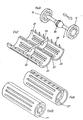
- an approximately symmetrical ball is formed on the stamp 3 with the central axis of the winding body 2 running in the longitudinal direction 7 of the winder 13 arranged.
- the inner surface of the winding body is formed in sections as an inner cone 14 with latching levels 15 and 16 for the ball 13 adjoining its two ends. The design is carried out so that when the ball 13 is arranged on the locking level 16 with a smaller inner diameter, the winding body 2 is spread out but when the ball 13 is arranged on the locking level 15 with the larger inner diameter it shrinks.
- the two positions of the ball 13 and correspondingly the two winding body settings with minimum diameter and maximum diameter are shown in FIGS. 1 and 2 for comparison.
- the provided for fixing the twisted hair on the winder 1 strap 4 can in principle on any a way with the longitudinal ends 5 and 6 of the winding body 2 are connected. It may be expedient to connect the tensioning strap 4 according to FIG. 3, in particular in one piece, to the one longitudinal end 17 of the punch 3.
- the tensioning band 4 is preferably attached to the longitudinal end 17 of the punch to be pulled when the winding body 2 is spread. It is thereby achieved that when the tensioning band 4 is tightened, the punch 3 (and possibly the ball 13 arranged thereon) is automatically drawn into a position according to FIG. 2, in which the winding body has the position with the maximum diameter.
- the stamp 3 is not connected to a ball 13 which interacts with an inner cone 14 of the winding body 2, but rather to a plate lamella 18, which can be folded in by pressing the stamp 3 in the radial direction according to FIG. 4 or according to FIG. 5 is spread.
- the stamp 3 can be designed as a guide 19 in which a type of Bowden cable 20 can be moved in the longitudinal direction 7 by pulling or pushing the actuating button 11.
- the plate lamella can be firmly connected to the guide 19 and / or to the inner surface 21 of the winding body 2 - on the latter at least in sections. 4 and 5, too, the winding body 2 can consist of rod lamellae 8 running in the longitudinal direction 7, preferably with an elastic outer skin 9 stretched over it.
- Mechanical means other than those according to FIGS. 1 to 5 can also be provided for expanding or collapsing the winding body.
- the stretching and relaxing can be done on an inclined plane.
- the winding body itself can instead of individual longitudinal slats consist of a cylinder with a longitudinal gap, two separate half-shells, three-thirds shells, four quarter-shells, etc.
- a hinge-like connection between the shells is expediently provided, possibly except for a single dividing line.
- FIG. 6 consists of two half-shells 22 and 23 which, when used along a toothing 24, mesh more or less closely.
- a folding hinge 27 and possibly guide cams 28 can also be provided on the dividing lines 25 and 26 of the half-shells 22 and 23 in the case of FIG. 7 on one side and possibly on the other side.
- the dividing lines 25 and 26 in the form of tongue and groove according to FIG. 11. If folding hinges are used to connect the partial shells of the winding body 2, two half-shells can be formed according to FIG. in the radial direction, running hinge 29 are connected.
- the hinges connecting the partial shells - each in one or more parts - can also be designed in such a way that individual longitudinal strips of the winding body shell are to be folded radially inward in order to collapse the hairstyle curler, in such a way that the periphery of the winding body in the longitudinal strips in question is, as it were, formed as a groove.
- the stamp 3 has a cone 30 (outer cone) arranged symmetrically with respect to the longitudinal axis 7 of the winding body.
- This cone 30 is assigned an inner cone 31 rectified on the inner surface 21 of the winding former.
- the cones - especially the inner cone - can consist of the shape of the winding body 2 and any openings 10 provided therein correspondingly shaped lamellae.
- a two-part circular ring 32 fastened to the inner surface 21 of the respective half-shell 22 or 23 is arranged in the exemplary embodiment according to FIG. 7, the bore 33 of which corresponds to the smaller diameter of the associated cone 30 fastened to the punch 3.
- the stamp 3 according to FIG. 8 is inserted into the winding body 2 according to FIG. 7 and this is closed by means of the folding hinge 27, the circumference of the winding body can be widened by pressing one or the other actuating button 11, 12 of the stamp 3 according to FIG. 9 or according to FIG 10 to be shrunk.
- a double cone is provided, by means of which it is possible to reduce the circumference of the screwed-in winding body by pressure on one or the other longitudinal end.
- the internal mechanics of the hairstyle winder according to FIG. 11 shown as an explosive pattern are designed.
- the main difference is that instead of one cone 30, two cones 30a and 30b (outer cones on the stamp) are provided, which correspond to inner cones 31a and 31b on the inner surface of the respective half-shell of the winding body 2.
- the tensioning strap 4 is attached to that longitudinal end of the stamp 3 attached, which is to pull out to expand the hairstyle curler in the direction of the inside of the curler.
- the tensioning strap 4 can be locked via an eyelet 34 on a hook 35 or the like of the actuating button 5 located there.
- the stamp 3 is surrounded by an elastically attached ring 36, the ring 36 engaging in an annular groove 37 in the inner surface 21 of the respective partial shell of the winding body 2.
- the annular groove 37 is preferably deeper in the radial direction than the dimension of the maximum change in diameter of the winding body 2 provided.
- the ring 36 which is made, for example, of rubber or another elastic material and / or is correspondingly elastically suspended, has the task of always changing the punch 3 into a normal or to reset the original position. As a rule, the position in which the hair stylist has its maximum diameter is selected as the original length. This ensures that the winder always has the largest diameter when it is screwed in and can only be moved from the original position into a position with a reduced diameter by moving the punch 3 or other actuating means.
- FIGS. 13 to 16 show a hairstyle winder in which the circumference is changed via slots 39 provided in disks 38 attached to the longitudinal ends of the stamp 3.
- Cams 41 which are firmly connected to the partial shells 40 of the winding body shell engage in the slots 39. Since the slots 39 are clearly inclined, for example inclined by 30 ° to 60 °, against which the circular surface covered by the cams when the punch 3 is rotated about its longitudinal axis 7 is defined by Rela tiv rotation of the winding body jacket and stamp an expansion or contraction of the winding body 2 reached.
- FIGS. 21 to 25 consist of partial shells 42 which extend in the longitudinal direction 7 and which are integrally connected to one another by multi-part film hinges 43.
- the parts that abut each other on the peripheral periphery can be fixed, i.e. inseparable, to be connected.
- the collapse of a winding body is brought about by pulling in the partial shells or film hinges in the radial direction.
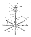
- the stamp 3 which can be rotated about its longitudinal axis 7, has a cross section in the form of a cam star 44 at two points.
- the individual cams 45 of the star 44 are assigned 2 counter cams 46 on the inner surface 21 of the winding body, such that the cams 45, 46 stand tip to tip in the position with the maximum winder circumference and the counter cams (or outer cams) 46 engage in the armpits 47 between the cams 46 of the star 44 in the position with the minimum winding circumference.
- slots 48 can be provided (for example also for locking purposes), similar to the exemplary embodiment according to FIGS. 13 to 16, which engage in the cams 48 projecting from the winding body 2.
- FIGS. 26 to 46 are used to explain features of the hairstyle winder which are particularly favorable for one-part or two-part manufacture by injection molding.
- all of these winders can be expanded and collapsed in the same way as the previous devices and equipped with a tensioning strap.
- the embodiment according to FIGS. 1 to 3 can advantageously be produced according to the principle described below.
- the entire hairstyle winder according to FIGS. 26 to 32 can be produced in one piece by the injection molding process if the bar lamellae 8 are molded in a manner pivoted in a direction antiparallel to the longitudinal direction 7 of the winder in a direction 180 ° from the working position.
- FIG. 27 An enlarged drawing of the free end piece of a bar lamella 8 is shown in perspective in FIG. 27.
- 26 and 27 have latching grooves and springs 57 on the side edges facing the respective neighboring lamella, which enable the free longitudinal ends of the bar lamellae 8 to be ring-shaped around the punch 3 after the pivoting in the direction of arrow 55 into the working position to snap into one another such that the free ends of the bar lamellae 8 encompass the circumference of the longitudinal end 6 of the punch 3 as a fixed ring — movable relative to the punch.
- the bar slat 3 has two additional film hinges 58 adjacent to the free end.
- FIGS. 29 to 32 it is explained how a hairdressing device erected from the blank according to FIG. 26 can be operated in practice.
- the winding body is expanded in principle in a manner similar to that in FIGS. 1 and 2, in that the radial plate on its circumference 59 stamp 3 is moved in the longitudinal direction 7 of the winder so that the plates 59 reach the upper locking position 15 of the cone pieces 56.
- the film hinges 53 and 58 lying closer to the stamp 3 are then stretched and the film hinges 53 and 58 further away from the stamp 3 are bent by approximately 90 °.
- This relative position changes when the plunger 3 is pressed in the direction 60 according to FIG. 31 and the plates 59 disengage from the upper locking levels 15 of the cone pieces 56. Because by moving the stamp 3 in the direction 60 the entire winding body 2 is simultaneously stretched parallel to the longitudinal axis 7, the film hinges 53 and 58 adjacent to the stamp 3 are bent and the respective other film hinges 53 and 58 are stretched to a greater or lesser extent. As a result, the radius of the winding body 2 is reduced approximately by the distance between adjacent film hinges 53 and 58; the ratio results approximately from a comparison of FIGS. 30 and 32.
- the hairstyle winder can also be produced in two parts by injection molding. Two exemplary embodiments are explained with reference to FIGS. 33 to 39 and 40 to 46.
- the body produced directly by spraying consists of approximately radial, star-shaped from the punch 3 or from the circumference of a rod lamella 8 projecting from the periphery of a disc 54 attached to its longitudinal end 5 (similar to FIG. 26). These are similar to those in FIG 26 and 27 are equipped along their length with one, two or more cone pieces 56 to match plates 59 surrounding stamp 3. At the boundary between the pane 54 and the bar slats 8, two film hinges 53 running parallel to one another are again provided.
- two film hinges 58 running parallel to one another are also produced at the free longitudinal end of the rod slats 8.
- the longitudinal ends of the rod slats 8 themselves are designed as latching cams 61, which are to be latched into latching holes 62 of a latching piece 63 which can be slidably placed on the free end 6 of the punch 3, preferably with an actuating button 64.
- 35 and 38 therefore need the rod to mount the hairstyle winder lamellae 8 to be pivoted in the arrow direction 55 only by about 90 ° until they are parallel to the longitudinal axis 7 of the winding body 3.
- the one component to be produced directly by injection molding consists of the rod fins 8, e.g. with cone pieces 56, and a plate 54 holding the plate slats 8 together via film hinges 53 with a plug guide 67 for inserting the separately manufactured stamp 3 according to FIG. 41.
- the stamp 3 has a fitting part 68 for the plug guide 67 at one longitudinal end and a fitting at the other longitudinal end Coupling part 69 for latching locking cams 70 provided at the longitudinal end of each of the rod plates 8.
- the stamp 3 is inserted with the fitting part 68 first in the direction of arrow 71 into the cylindrical basket spanned by the rod plates 8 according to FIG. 40.
Landscapes
- Hair Curling (AREA)
Priority Applications (1)
| Application Number | Priority Date | Filing Date | Title |
|---|---|---|---|
| AT86114119T ATE75110T1 (de) | 1985-10-21 | 1986-10-11 | Frisurenwickler. |
Applications Claiming Priority (5)
| Application Number | Priority Date | Filing Date | Title |
|---|---|---|---|
| DE3537374 | 1985-10-21 | ||
| DE3537374 | 1985-10-21 | ||
| DE3544275 | 1985-12-14 | ||
| DE8535210U DE8535210U1 (fr) | 1985-10-21 | 1985-12-14 | |
| DE19853544275 DE3544275A1 (de) | 1985-10-21 | 1985-12-14 | Frisurenwickler |
Publications (3)
| Publication Number | Publication Date |
|---|---|
| EP0219783A2 true EP0219783A2 (fr) | 1987-04-29 |
| EP0219783A3 EP0219783A3 (en) | 1988-10-12 |
| EP0219783B1 EP0219783B1 (fr) | 1992-04-22 |
Family
ID=27193604
Family Applications (1)
| Application Number | Title | Priority Date | Filing Date |
|---|---|---|---|
| EP86114119A Expired - Lifetime EP0219783B1 (fr) | 1985-10-21 | 1986-10-11 | Bigoudi pour cheveux |
Country Status (3)
| Country | Link |
|---|---|
| US (2) | US4856542A (fr) |
| EP (1) | EP0219783B1 (fr) |
| DE (2) | DE3544275A1 (fr) |
Cited By (2)
| Publication number | Priority date | Publication date | Assignee | Title |
|---|---|---|---|---|
| WO1992014378A1 (fr) * | 1991-02-14 | 1992-09-03 | Braun Aktiengesellschaft | Appareil pour le soin des cheveux |
| WO2007069048A2 (fr) * | 2005-12-14 | 2007-06-21 | Dickson Industrial Co., Ltd. | Bigoudi extensible |
Families Citing this family (21)
| Publication number | Priority date | Publication date | Assignee | Title |
|---|---|---|---|---|
| US5694954A (en) * | 1995-10-11 | 1997-12-09 | Habibi; Masood | Heated hair curler with adjustable diameter and heating unit therefor |
| US5662128A (en) * | 1995-10-11 | 1997-09-02 | Habibi; Masood | Adjustable hair curler and method of use |
| US5890496A (en) * | 1995-10-11 | 1999-04-06 | Habibi; Masood | Heatable hair curler with adjustable diameter |
| AU3799197A (en) | 1996-07-25 | 1998-02-20 | Whitehill Oral Technologies, Inc. | Toothbrush with improved cleaning and abrasion efficiency |
| US6036635A (en) * | 1997-02-26 | 2000-03-14 | Altshuler; Yakov | Erection control system |
| US5887599A (en) * | 1997-09-10 | 1999-03-30 | Habibi; Masood | Adjustable hair curler and method of use |
| US6725495B1 (en) * | 1999-08-24 | 2004-04-27 | Masood Habibi | Adjustable hair brush |
| US6363946B1 (en) * | 2000-05-11 | 2002-04-02 | James W. Sumner | Longitudinally adjustable permanent wave rods |
| US6386208B1 (en) * | 2001-09-27 | 2002-05-14 | Alice M. Reid | Hair accessory and binding device |
| DE602006010046D1 (de) * | 2006-06-19 | 2009-12-10 | Procter & Gamble | Verfahren zur Haarverformung mit einem superabsorbierenden Material |
| EP2133004A1 (fr) * | 2008-06-11 | 2009-12-16 | Great Lengths S.r.L. | Bigoudi expansible |
| EP2773237B1 (fr) | 2011-10-31 | 2019-12-18 | Masood Habibi | Mécanisme cylindrique à diamètre réglable |
| US10206425B2 (en) * | 2015-07-14 | 2019-02-19 | Dynavap, LLC | Exothermal vaporizer |
| GB2526768B (en) | 2014-03-20 | 2017-02-15 | Dyson Technology Ltd | Attachment for a hand held appliance |
| GB2526049B (en) * | 2014-03-20 | 2017-04-12 | Dyson Technology Ltd | Attachment for a hand held appliance |
| KR102179911B1 (ko) * | 2014-03-20 | 2020-11-17 | 다이슨 테크놀러지 리미티드 | 휴대용 기구를 위한 부착물 |
| CN104824955B (zh) * | 2015-05-18 | 2017-01-18 | 东莞港电电器制品有限公司 | 一种具有直径大小可变结构的烫发器 |
| WO2017163005A1 (fr) | 2016-03-24 | 2017-09-28 | Dyson Technology Limited | Accessoire pour appareil tenu en main |
| US11517089B2 (en) | 2016-09-20 | 2022-12-06 | Olga Hassan Dolah | Hair roller assembly apparatus and method of use |
| US11134765B2 (en) * | 2018-11-08 | 2021-10-05 | Sutra Beauty, Inc. | Variable diameter adjustable hair tool |
| DE102019109760B4 (de) * | 2019-04-12 | 2021-05-12 | Renate Baier | Haarwickler |
Citations (6)
| Publication number | Priority date | Publication date | Assignee | Title |
|---|---|---|---|---|
| US2415586A (en) * | 1944-11-20 | 1947-02-11 | Products Develeopment Inc | Curling rod |
| FR1000538A (fr) * | 1946-02-25 | 1952-02-13 | Bigoudi, particulièrement pour l'ondulation permanente | |
| FR1003318A (fr) * | 1949-12-14 | 1952-03-17 | Procédé de bouclage des cheveux et dispositifs en permettant la mise en oeuvre | |
| FR1011323A (fr) * | 1949-01-17 | 1952-06-23 | Bigoudi-carde escamotable | |
| DE1457397A1 (de) * | 1964-04-06 | 1969-02-06 | Erwin Eger | Haarwickler |
| US3623491A (en) * | 1969-08-06 | 1971-11-30 | Flairescene Ltd | Hair roller |
Family Cites Families (16)
| Publication number | Priority date | Publication date | Assignee | Title |
|---|---|---|---|---|
| US1199550A (en) * | 1916-06-07 | 1916-09-26 | Paul E Herrmann | Hair curling and waving apparatus. |
| DE460580C (de) * | 1927-01-08 | 1928-06-01 | Peter Lichem | Doppelt kegelfoermiges Wickelrohr zur Herstellung von Haardauerwellen |
| US2290578A (en) * | 1941-09-06 | 1942-07-21 | Eli R Boals | Expansible hair curling device |
| US2474449A (en) * | 1946-04-23 | 1949-06-28 | Curtis Helene Ind Inc | Expandible curling rod |
| US2753874A (en) * | 1953-10-07 | 1956-07-10 | Brancaccio Silvere | Expanding hair curling rod |
| US2853080A (en) * | 1955-04-20 | 1958-09-23 | Brancaccio Silvere | Expanding and retracting hair curler |
| DE955544C (de) * | 1955-05-12 | 1957-01-03 | Hermann Warth | Lockenwickler |
| CH337311A (de) * | 1955-10-04 | 1959-03-31 | Dinger Gabrielle | Lockenwickler |
| US2853081A (en) * | 1956-04-16 | 1958-09-23 | Brancaccio Silvere | Expanding and contracting hair curler |
| US2860645A (en) * | 1957-03-14 | 1958-11-18 | Brancaccio Silvere | Expandable permanent wave rod |
| FR1279457A (fr) * | 1960-11-10 | 1961-12-22 | Perfectionnement apporté aux appareillages pour ondulations indéfrisables | |
| US3495601A (en) * | 1967-11-07 | 1970-02-17 | William Garrett | Hair waving rod |
| US3583409A (en) * | 1968-10-30 | 1971-06-08 | Robert Rios | Expansible and contractable hair curler |
| US3583406A (en) * | 1969-08-28 | 1971-06-08 | American Brands | Production of a filter cigarette |
| US3707155A (en) * | 1972-01-24 | 1972-12-26 | Alfred A Lemberg | Expandable hair curler |
| US4456020A (en) * | 1983-12-19 | 1984-06-26 | General Electric Company | Adjustable hair curler |
-
1985
- 1985-12-14 DE DE19853544275 patent/DE3544275A1/de not_active Withdrawn
- 1985-12-14 DE DE8535210U patent/DE8535210U1/de not_active Expired
-
1986
- 1986-10-11 EP EP86114119A patent/EP0219783B1/fr not_active Expired - Lifetime
- 1986-10-21 US US06/921,653 patent/US4856542A/en not_active Expired - Fee Related
-
1989
- 1989-07-17 US US07/380,935 patent/US5020552A/en not_active Expired - Fee Related
Patent Citations (6)
| Publication number | Priority date | Publication date | Assignee | Title |
|---|---|---|---|---|
| US2415586A (en) * | 1944-11-20 | 1947-02-11 | Products Develeopment Inc | Curling rod |
| FR1000538A (fr) * | 1946-02-25 | 1952-02-13 | Bigoudi, particulièrement pour l'ondulation permanente | |
| FR1011323A (fr) * | 1949-01-17 | 1952-06-23 | Bigoudi-carde escamotable | |
| FR1003318A (fr) * | 1949-12-14 | 1952-03-17 | Procédé de bouclage des cheveux et dispositifs en permettant la mise en oeuvre | |
| DE1457397A1 (de) * | 1964-04-06 | 1969-02-06 | Erwin Eger | Haarwickler |
| US3623491A (en) * | 1969-08-06 | 1971-11-30 | Flairescene Ltd | Hair roller |
Cited By (3)
| Publication number | Priority date | Publication date | Assignee | Title |
|---|---|---|---|---|
| WO1992014378A1 (fr) * | 1991-02-14 | 1992-09-03 | Braun Aktiengesellschaft | Appareil pour le soin des cheveux |
| WO2007069048A2 (fr) * | 2005-12-14 | 2007-06-21 | Dickson Industrial Co., Ltd. | Bigoudi extensible |
| WO2007069048A3 (fr) * | 2005-12-14 | 2007-09-20 | Dickson Industrial Co Ltd | Bigoudi extensible |
Also Published As
| Publication number | Publication date |
|---|---|
| US5020552A (en) | 1991-06-04 |
| DE3544275A1 (de) | 1987-04-23 |
| EP0219783B1 (fr) | 1992-04-22 |
| EP0219783A3 (en) | 1988-10-12 |
| US4856542A (en) | 1989-08-15 |
| DE8535210U1 (fr) | 1987-01-15 |
Similar Documents
| Publication | Publication Date | Title |
|---|---|---|
| EP0219783B1 (fr) | Bigoudi pour cheveux | |
| WO2013050386A1 (fr) | Brosse d'application de mascara creuse | |
| WO2012055727A1 (fr) | Dispositif applicateur pour appliquer un cosmétique, élément applicateur à cet effet ainsi qu'unité cosmétique présentant le dispositif applicateur | |
| DE2909386C2 (fr) | ||
| WO2000069308A1 (fr) | Dispositif d'application pour coloration de meches de cheveux | |
| DE2149932C3 (de) | Selbstöffnender Schirm | |
| DE102019107890A1 (de) | Vorrichtung zum Auftragen einer abtragbaren Masse in Form eines Stiftes | |
| DE69915682T2 (de) | Haarklammer für das Frisörhandwerk | |
| DE3003612A1 (de) | Lockenwickler | |
| EP3827695B1 (fr) | Dispositif d'enroulement des mèches de cheveux | |
| EP0056605B1 (fr) | Bigoudi et son application à la mise en forme des cheveux | |
| DE1291867B (de) | Lockenwickler | |
| DE3006459C2 (fr) | ||
| DE19505312A1 (de) | Wickelkern zum Wickeln von flächigen Gegenständen | |
| DE8529808U1 (de) | Frisurenwickler | |
| DE3634842A1 (de) | Lockenwickler | |
| EP3793398B1 (fr) | Pince a cheveux | |
| AT395201B (de) | Einrichtung an einem verschwenkbare lamellen aufweisenden rafflamellenstore | |
| DE3606718A1 (de) | Geraet zum formen von chemisch erzeugten dauerwellen im haar | |
| DE3616336A1 (de) | Lockenwickler | |
| DE3016455C2 (de) | Vorrichtung zum Formen von Haarlocken | |
| DE887993C (de) | Lockenwickler | |
| DE602005000327T2 (de) | Anordnung zum Aufwickeln von Haarsträhnen | |
| EP0039072A2 (fr) | Bigoudi | |
| DE3709273A1 (de) | Geraet zum formen von chemisch erzeugten dauerwellen im haar |
Legal Events
| Date | Code | Title | Description |
|---|---|---|---|
| PUAI | Public reference made under article 153(3) epc to a published international application that has entered the european phase |
Free format text: ORIGINAL CODE: 0009012 |
|
| AK | Designated contracting states |
Kind code of ref document: A2 Designated state(s): AT BE CH DE FR GB IT LI NL SE |
|
| PUAL | Search report despatched |
Free format text: ORIGINAL CODE: 0009013 |
|
| AK | Designated contracting states |
Kind code of ref document: A3 Designated state(s): AT BE CH DE FR GB IT LI NL SE |
|
| 17P | Request for examination filed |
Effective date: 19881105 |
|
| 17Q | First examination report despatched |
Effective date: 19900503 |
|
| ITTA | It: last paid annual fee | ||
| GRAA | (expected) grant |
Free format text: ORIGINAL CODE: 0009210 |
|
| AK | Designated contracting states |
Kind code of ref document: B1 Designated state(s): AT BE CH DE FR GB IT LI NL SE |
|
| REF | Corresponds to: |
Ref document number: 75110 Country of ref document: AT Date of ref document: 19920515 Kind code of ref document: T |
|
| REF | Corresponds to: |
Ref document number: 3684985 Country of ref document: DE Date of ref document: 19920527 |
|
| GBT | Gb: translation of ep patent filed (gb section 77(6)(a)/1977) | ||
| ITF | It: translation for a ep patent filed |
Owner name: STUDIO JAUMANN |
|
| ET | Fr: translation filed | ||
| PGFP | Annual fee paid to national office [announced via postgrant information from national office to epo] |
Ref country code: CH Payment date: 19920924 Year of fee payment: 7 |
|
| PGFP | Annual fee paid to national office [announced via postgrant information from national office to epo] |
Ref country code: GB Payment date: 19920929 Year of fee payment: 7 |
|
| PGFP | Annual fee paid to national office [announced via postgrant information from national office to epo] |
Ref country code: FR Payment date: 19921005 Year of fee payment: 7 Ref country code: DE Payment date: 19921005 Year of fee payment: 7 Ref country code: AT Payment date: 19921005 Year of fee payment: 7 |
|
| PGFP | Annual fee paid to national office [announced via postgrant information from national office to epo] |
Ref country code: SE Payment date: 19921014 Year of fee payment: 7 |
|
| PGFP | Annual fee paid to national office [announced via postgrant information from national office to epo] |
Ref country code: BE Payment date: 19921028 Year of fee payment: 7 |
|
| PGFP | Annual fee paid to national office [announced via postgrant information from national office to epo] |
Ref country code: NL Payment date: 19921031 Year of fee payment: 7 |
|
| PLBE | No opposition filed within time limit |
Free format text: ORIGINAL CODE: 0009261 |
|
| STAA | Information on the status of an ep patent application or granted ep patent |
Free format text: STATUS: NO OPPOSITION FILED WITHIN TIME LIMIT |
|
| 26N | No opposition filed | ||
| PG25 | Lapsed in a contracting state [announced via postgrant information from national office to epo] |
Ref country code: GB Effective date: 19931011 Ref country code: AT Effective date: 19931011 |
|
| PG25 | Lapsed in a contracting state [announced via postgrant information from national office to epo] |
Ref country code: SE Effective date: 19931012 |
|
| PG25 | Lapsed in a contracting state [announced via postgrant information from national office to epo] |
Ref country code: LI Effective date: 19931031 Ref country code: CH Effective date: 19931031 Ref country code: BE Effective date: 19931031 |
|
| BERE | Be: lapsed |
Owner name: HENKEL K.G.A.A. Effective date: 19931031 |
|
| PG25 | Lapsed in a contracting state [announced via postgrant information from national office to epo] |
Ref country code: NL Effective date: 19940501 |
|
| GBPC | Gb: european patent ceased through non-payment of renewal fee |
Effective date: 19931011 |
|
| NLV4 | Nl: lapsed or anulled due to non-payment of the annual fee | ||
| PG25 | Lapsed in a contracting state [announced via postgrant information from national office to epo] |
Ref country code: FR Effective date: 19940630 |
|
| REG | Reference to a national code |
Ref country code: CH Ref legal event code: PL |
|
| PG25 | Lapsed in a contracting state [announced via postgrant information from national office to epo] |
Ref country code: DE Effective date: 19940701 |
|
| REG | Reference to a national code |
Ref country code: FR Ref legal event code: ST |
|
| EUG | Se: european patent has lapsed |
Ref document number: 86114119.0 Effective date: 19940510 |
|
| PG25 | Lapsed in a contracting state [announced via postgrant information from national office to epo] |
Ref country code: IT Free format text: LAPSE BECAUSE OF NON-PAYMENT OF DUE FEES;WARNING: LAPSES OF ITALIAN PATENTS WITH EFFECTIVE DATE BEFORE 2007 MAY HAVE OCCURRED AT ANY TIME BEFORE 2007. THE CORRECT EFFECTIVE DATE MAY BE DIFFERENT FROM THE ONE RECORDED. Effective date: 20051011 |