EP0219783A2 - Hair rollers - Google Patents
Hair rollers Download PDFInfo
- Publication number
- EP0219783A2 EP0219783A2 EP86114119A EP86114119A EP0219783A2 EP 0219783 A2 EP0219783 A2 EP 0219783A2 EP 86114119 A EP86114119 A EP 86114119A EP 86114119 A EP86114119 A EP 86114119A EP 0219783 A2 EP0219783 A2 EP 0219783A2
- Authority
- EP
- European Patent Office
- Prior art keywords
- winding body
- stamp
- hairstylist
- longitudinal
- circumference
- Prior art date
- Legal status (The legal status is an assumption and is not a legal conclusion. Google has not performed a legal analysis and makes no representation as to the accuracy of the status listed.)
- Granted
Links
Images


Classifications
-
- A—HUMAN NECESSITIES
- A45—HAND OR TRAVELLING ARTICLES
- A45D—HAIRDRESSING OR SHAVING EQUIPMENT; EQUIPMENT FOR COSMETICS OR COSMETIC TREATMENTS, e.g. FOR MANICURING OR PEDICURING
- A45D2/00—Hair-curling or hair-waving appliances ; Appliances for hair dressing treatment not otherwise provided for
- A45D2/12—Hair winders or hair curlers for use parallel to the scalp, i.e. flat-curlers
- A45D2/24—Hair winders or hair curlers for use parallel to the scalp, i.e. flat-curlers of multi-part type, e.g. with sliding parts other than for fastening
Definitions
- the invention relates to a hair styler consisting of a bobbin to be screwed into the hair, in particular with a tensioning band extending at least from one to the other longitudinal end of the bobbin for fixing the untwisted hair.
- Usual hair style curlers of this type which are also referred to as water wave curlers, consist, for example, of a metal cylinder of constant diameter with a brush inserted, or of a flocked plastic cylinder.
- the hair is arrested by holding pins, so-called postiche.
- the curlers are screwed into damp hair and, after the hair has dried, are unwound in the opposite direction. Unwinding is time-consuming and can lead to a partial destruction of the curls if you act carelessly.
- the invention has for its object to provide a curler that is easy to detach from the hair and when used the risk of disturbing the curls formed is significantly reduced.
- the winder should at the same time be designed so that it can be produced in one piece or in two pieces by injection molding.
- the general solution according to the invention is characterized for the hairstyle winder mentioned at the outset by an adjustable winding body circumference and actuating means for reducing the circumference of a screwed-in winding body.
- a winding body wrapped with hair, according to the invention can be shrunk, preferably after the curl has dried, to such an extent that it can be pulled out of the curl laterally. Because of the reduced diameter of the winding body, there is no risk of the dried curl being impaired.
- the winding body according to the invention can consist, for example, in its outer skin of a material which is elastically stretchable in the circumferential direction.
- An elastic skin made of plastic or rubber, which can also contain holes for ventilation, on a frame that can be mechanically expanded or contracted in the radial direction is suitable.
- the winding body can also consist of an essentially only flexible, in principle cylindrical base body with at least one dividing line extending from one longitudinal end to the other.
- the means for enlarging or reducing the circumference of the winding body can then consist essentially of pushing the winding body apart from the inside and thus increasing the gap on the respective subdivision line.
- To reduce the circumference of the winding body only the force acting from the inside is then to be relaxed, so that the winding body again assumes its original, for example cylindrical, shape.
- the winding body can be produced from partial shells or the like which are delimited in the longitudinal direction of the dividing lines.
- the partial shells can butt against one another at the dividing lines, with tongue and groove or toothed and / or connected with a hinge or the like.
- adjustment devices in the interior of the winding body or on one or both open ends of the cylindrical body serve as means for expanding or collapsing the winding body.
- a stamp guided in the winding body and to be actuated from at least one longitudinal end of the winding body and means interacting with the stamp are provided for expanding or contracting the circumference or diameter of the winding body.
- stamp here includes not only a slide designed as a solid rod or the like, but generally means for actuating the expanding and / or collapsing devices provided in the inside of the winding body, for example a guide with a Bowden cable which is used to adjust the circumference of the winding body serves to fall under the term "stamp".
- the stamp preferably has a position within the winding body which is automatic or which is automatically adjusted when the hair is opened, in which the winding body has its maximum diameter. In use, it cannot then happen that a curl is turned on a winding body of minimal diameter and therefore cannot be separated from the winding body after drying without unwinding.
- the above-mentioned preferred position of the stamp within the winding body is achieved, for example, by an elastic restoring force acting on the stamp or by connecting the tensioning band and stamp such that when the tensioning band is fastened, the stamp is automatically drawn into the position in which the winding body has the maximum diameter owns.
- the hairstyle winder consists of a winding body to be screwed into the hair, which is made up of a plurality of bar lamellae which are parallel to one another and to the longitudinal axis of the winder, and which has means for changing the circumference of the winding body which cooperate with the punch lying in the longitudinal axis of the winder.
- the bar slats are formed with one of their longitudinal ends on one longitudinal end of the stamp via at least one film hinge and if the opposite longitudinal ends of the bar slats have means for latching in a position on the circumference of the punch.
- Such a winding body can be produced in one or two parts by injection molding and can be erected or assembled in the simplest way.
- a hairstyle winder of this type can be produced in one piece if the rod slats are produced when sprayed in a position 180 ° from the working position to a position antiparallel to the longitudinal axis of the winder and pivoted for assembly using the film hinges by 180 ° and at the free longitudinal end of the stamp with one another or with the stamp are snapped together.
- the hairstyle winder can also be produced in two parts by injection molding if the one part consists of the stamp and the rod slats formed thereon via at least one film hinge and the other part consists of a snap-on part for the free ends of the rod slats to be plugged onto the free stamp end.
- the snap-on part to be clipped on can at the same time be designed as an actuation button for longitudinally displacing the stamp in the completely assembled hairstyle winder.
- the material distribution in two-part production by injection molding can also be made in such a way that the rod lamellas are formed by means of film hinges on an essentially circular disc which is to be connected to a coupling end piece of a stamp which is to be produced separately by injection molding.
- the free longitudinal ends of the rod slats facing away from the disc can then be anchored in a snap-in head at the opposite longitudinal end of the stamp in the working position.
- the winding body can be produced in one or two parts entirely by injection molding and can be finished in a few simple steps Hair curlers can be mounted.
- elements of a jointly spanned inner cone can be molded onto the inner surface of each of the bar lamellae of the erected winding body, such that a plate assigned to the inner cone and radially molded onto the die collapses by moving the die in the longitudinal direction of the winder relative to the bar slats and can be expanded.
- the relative longitudinal movement of the stamp and the bar slats as well as the expansion and contraction of the radius of the bobbin is made possible by the film hinges provided in pairs in the area of the longitudinal ends of the bar slats.
- the winding body 2 can consist of individual rod slats 8 extending in the longitudinal direction 7 of the winder, which are held together loosely and / or elastically in the circumferential direction.
- the rod slats 8 can be arranged on the inside of an outer skin 9 made of elastic plastic or rubber.
- the outer skin 9 can have ventilation openings 10.
- the stamp 3 guided in the winding body 2 has an actuation button 11 or 12 on at least one longitudinal end.
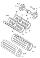
- an approximately symmetrical ball is formed on the stamp 3 with the central axis of the winding body 2 running in the longitudinal direction 7 of the winder 13 arranged.
- the inner surface of the winding body is formed in sections as an inner cone 14 with latching levels 15 and 16 for the ball 13 adjoining its two ends. The design is carried out so that when the ball 13 is arranged on the locking level 16 with a smaller inner diameter, the winding body 2 is spread out but when the ball 13 is arranged on the locking level 15 with the larger inner diameter it shrinks.
- the two positions of the ball 13 and correspondingly the two winding body settings with minimum diameter and maximum diameter are shown in FIGS. 1 and 2 for comparison.
- the provided for fixing the twisted hair on the winder 1 strap 4 can in principle on any a way with the longitudinal ends 5 and 6 of the winding body 2 are connected. It may be expedient to connect the tensioning strap 4 according to FIG. 3, in particular in one piece, to the one longitudinal end 17 of the punch 3.
- the tensioning band 4 is preferably attached to the longitudinal end 17 of the punch to be pulled when the winding body 2 is spread. It is thereby achieved that when the tensioning band 4 is tightened, the punch 3 (and possibly the ball 13 arranged thereon) is automatically drawn into a position according to FIG. 2, in which the winding body has the position with the maximum diameter.
- the stamp 3 is not connected to a ball 13 which interacts with an inner cone 14 of the winding body 2, but rather to a plate lamella 18, which can be folded in by pressing the stamp 3 in the radial direction according to FIG. 4 or according to FIG. 5 is spread.
- the stamp 3 can be designed as a guide 19 in which a type of Bowden cable 20 can be moved in the longitudinal direction 7 by pulling or pushing the actuating button 11.
- the plate lamella can be firmly connected to the guide 19 and / or to the inner surface 21 of the winding body 2 - on the latter at least in sections. 4 and 5, too, the winding body 2 can consist of rod lamellae 8 running in the longitudinal direction 7, preferably with an elastic outer skin 9 stretched over it.
- Mechanical means other than those according to FIGS. 1 to 5 can also be provided for expanding or collapsing the winding body.
- the stretching and relaxing can be done on an inclined plane.
- the winding body itself can instead of individual longitudinal slats consist of a cylinder with a longitudinal gap, two separate half-shells, three-thirds shells, four quarter-shells, etc.
- a hinge-like connection between the shells is expediently provided, possibly except for a single dividing line.
- FIG. 6 consists of two half-shells 22 and 23 which, when used along a toothing 24, mesh more or less closely.
- a folding hinge 27 and possibly guide cams 28 can also be provided on the dividing lines 25 and 26 of the half-shells 22 and 23 in the case of FIG. 7 on one side and possibly on the other side.
- the dividing lines 25 and 26 in the form of tongue and groove according to FIG. 11. If folding hinges are used to connect the partial shells of the winding body 2, two half-shells can be formed according to FIG. in the radial direction, running hinge 29 are connected.
- the hinges connecting the partial shells - each in one or more parts - can also be designed in such a way that individual longitudinal strips of the winding body shell are to be folded radially inward in order to collapse the hairstyle curler, in such a way that the periphery of the winding body in the longitudinal strips in question is, as it were, formed as a groove.
- the stamp 3 has a cone 30 (outer cone) arranged symmetrically with respect to the longitudinal axis 7 of the winding body.
- This cone 30 is assigned an inner cone 31 rectified on the inner surface 21 of the winding former.
- the cones - especially the inner cone - can consist of the shape of the winding body 2 and any openings 10 provided therein correspondingly shaped lamellae.
- a two-part circular ring 32 fastened to the inner surface 21 of the respective half-shell 22 or 23 is arranged in the exemplary embodiment according to FIG. 7, the bore 33 of which corresponds to the smaller diameter of the associated cone 30 fastened to the punch 3.
- the stamp 3 according to FIG. 8 is inserted into the winding body 2 according to FIG. 7 and this is closed by means of the folding hinge 27, the circumference of the winding body can be widened by pressing one or the other actuating button 11, 12 of the stamp 3 according to FIG. 9 or according to FIG 10 to be shrunk.
- a double cone is provided, by means of which it is possible to reduce the circumference of the screwed-in winding body by pressure on one or the other longitudinal end.
- the internal mechanics of the hairstyle winder according to FIG. 11 shown as an explosive pattern are designed.
- the main difference is that instead of one cone 30, two cones 30a and 30b (outer cones on the stamp) are provided, which correspond to inner cones 31a and 31b on the inner surface of the respective half-shell of the winding body 2.
- the tensioning strap 4 is attached to that longitudinal end of the stamp 3 attached, which is to pull out to expand the hairstyle curler in the direction of the inside of the curler.
- the tensioning strap 4 can be locked via an eyelet 34 on a hook 35 or the like of the actuating button 5 located there.
- the stamp 3 is surrounded by an elastically attached ring 36, the ring 36 engaging in an annular groove 37 in the inner surface 21 of the respective partial shell of the winding body 2.
- the annular groove 37 is preferably deeper in the radial direction than the dimension of the maximum change in diameter of the winding body 2 provided.
- the ring 36 which is made, for example, of rubber or another elastic material and / or is correspondingly elastically suspended, has the task of always changing the punch 3 into a normal or to reset the original position. As a rule, the position in which the hair stylist has its maximum diameter is selected as the original length. This ensures that the winder always has the largest diameter when it is screwed in and can only be moved from the original position into a position with a reduced diameter by moving the punch 3 or other actuating means.
- FIGS. 13 to 16 show a hairstyle winder in which the circumference is changed via slots 39 provided in disks 38 attached to the longitudinal ends of the stamp 3.
- Cams 41 which are firmly connected to the partial shells 40 of the winding body shell engage in the slots 39. Since the slots 39 are clearly inclined, for example inclined by 30 ° to 60 °, against which the circular surface covered by the cams when the punch 3 is rotated about its longitudinal axis 7 is defined by Rela tiv rotation of the winding body jacket and stamp an expansion or contraction of the winding body 2 reached.
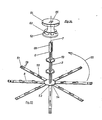
- FIGS. 21 to 25 consist of partial shells 42 which extend in the longitudinal direction 7 and which are integrally connected to one another by multi-part film hinges 43.
- the parts that abut each other on the peripheral periphery can be fixed, i.e. inseparable, to be connected.
- the collapse of a winding body is brought about by pulling in the partial shells or film hinges in the radial direction.
- the stamp 3 which can be rotated about its longitudinal axis 7, has a cross section in the form of a cam star 44 at two points.
- the individual cams 45 of the star 44 are assigned 2 counter cams 46 on the inner surface 21 of the winding body, such that the cams 45, 46 stand tip to tip in the position with the maximum winder circumference and the counter cams (or outer cams) 46 engage in the armpits 47 between the cams 46 of the star 44 in the position with the minimum winding circumference.
- slots 48 can be provided (for example also for locking purposes), similar to the exemplary embodiment according to FIGS. 13 to 16, which engage in the cams 48 projecting from the winding body 2.
- FIGS. 26 to 46 are used to explain features of the hairstyle winder which are particularly favorable for one-part or two-part manufacture by injection molding.
- all of these winders can be expanded and collapsed in the same way as the previous devices and equipped with a tensioning strap.
- the embodiment according to FIGS. 1 to 3 can advantageously be produced according to the principle described below.
- the entire hairstyle winder according to FIGS. 26 to 32 can be produced in one piece by the injection molding process if the bar lamellae 8 are molded in a manner pivoted in a direction antiparallel to the longitudinal direction 7 of the winder in a direction 180 ° from the working position.
- FIG. 27 An enlarged drawing of the free end piece of a bar lamella 8 is shown in perspective in FIG. 27.
- 26 and 27 have latching grooves and springs 57 on the side edges facing the respective neighboring lamella, which enable the free longitudinal ends of the bar lamellae 8 to be ring-shaped around the punch 3 after the pivoting in the direction of arrow 55 into the working position to snap into one another such that the free ends of the bar lamellae 8 encompass the circumference of the longitudinal end 6 of the punch 3 as a fixed ring — movable relative to the punch.
- the bar slat 3 has two additional film hinges 58 adjacent to the free end.
- FIGS. 29 to 32 it is explained how a hairdressing device erected from the blank according to FIG. 26 can be operated in practice.
- the winding body is expanded in principle in a manner similar to that in FIGS. 1 and 2, in that the radial plate on its circumference 59 stamp 3 is moved in the longitudinal direction 7 of the winder so that the plates 59 reach the upper locking position 15 of the cone pieces 56.
- the film hinges 53 and 58 lying closer to the stamp 3 are then stretched and the film hinges 53 and 58 further away from the stamp 3 are bent by approximately 90 °.
- This relative position changes when the plunger 3 is pressed in the direction 60 according to FIG. 31 and the plates 59 disengage from the upper locking levels 15 of the cone pieces 56. Because by moving the stamp 3 in the direction 60 the entire winding body 2 is simultaneously stretched parallel to the longitudinal axis 7, the film hinges 53 and 58 adjacent to the stamp 3 are bent and the respective other film hinges 53 and 58 are stretched to a greater or lesser extent. As a result, the radius of the winding body 2 is reduced approximately by the distance between adjacent film hinges 53 and 58; the ratio results approximately from a comparison of FIGS. 30 and 32.
- the hairstyle winder can also be produced in two parts by injection molding. Two exemplary embodiments are explained with reference to FIGS. 33 to 39 and 40 to 46.
- the body produced directly by spraying consists of approximately radial, star-shaped from the punch 3 or from the circumference of a rod lamella 8 projecting from the periphery of a disc 54 attached to its longitudinal end 5 (similar to FIG. 26). These are similar to those in FIG 26 and 27 are equipped along their length with one, two or more cone pieces 56 to match plates 59 surrounding stamp 3. At the boundary between the pane 54 and the bar slats 8, two film hinges 53 running parallel to one another are again provided.
- two film hinges 58 running parallel to one another are also produced at the free longitudinal end of the rod slats 8.
- the longitudinal ends of the rod slats 8 themselves are designed as latching cams 61, which are to be latched into latching holes 62 of a latching piece 63 which can be slidably placed on the free end 6 of the punch 3, preferably with an actuating button 64.
- 35 and 38 therefore need the rod to mount the hairstyle winder lamellae 8 to be pivoted in the arrow direction 55 only by about 90 ° until they are parallel to the longitudinal axis 7 of the winding body 3.
- the one component to be produced directly by injection molding consists of the rod fins 8, e.g. with cone pieces 56, and a plate 54 holding the plate slats 8 together via film hinges 53 with a plug guide 67 for inserting the separately manufactured stamp 3 according to FIG. 41.
- the stamp 3 has a fitting part 68 for the plug guide 67 at one longitudinal end and a fitting at the other longitudinal end Coupling part 69 for latching locking cams 70 provided at the longitudinal end of each of the rod plates 8.
- the stamp 3 is inserted with the fitting part 68 first in the direction of arrow 71 into the cylindrical basket spanned by the rod plates 8 according to FIG. 40.
Landscapes
- Hair Curling (AREA)
Abstract
Um bei einem aus einem in das Haar einzudrehenden Wickelkörper (2) und gegebenenfalls einem zum Festlegen des aufgedrehten Haars dienenden Spannband (4) bestehenden Frisurenwickler (1) ein seitliches Herausziehen des Wikkelkörpers (2) aus einer getrockneten Locke zu ermöglichen, wird der Wickelkörper (2) mit verstellbarem Umfang ausgebildet, und im Wickelkörperinnern oder an dessen Längsenden werden von außen her zu betätigende Mittel (3) zum Verringern des Umfangs eines eingedrehten Wickelkörpers angeordnet (Figur 1).
Description
Die Erfindung betrifft einen Frisurenwickler bestehend aus einem in das Haar einzudrehenden Wickelkörper, insbesondere mit einem zumindest von einem zum anderen Längsende des Wickelkörpers reichenden Spannband zum Festlegen des aufgedrehten Haars.The invention relates to a hair styler consisting of a bobbin to be screwed into the hair, in particular with a tensioning band extending at least from one to the other longitudinal end of the bobbin for fixing the untwisted hair.
Übliche Frisurenwickler dieser Art, die auch als Wasserwellwickler bezeichnet werden, bestehen beispielsweise aus einem Metallzylinder konstanten Durchmessers mit eingeschobener Bürste oder aus einem beflockten Kunststoffzylinder. Das Haar wird durch Haltenadeln, sogenannte Postiche, arretiert. Die Wickler werden ins feuchte Haar eingedreht und nach dem Trocknen der Haare in entgegengesetzter Richtung abgewickelt. Das Abwickeln ist zeitaufwendig und kann bei unachtsamer Handlungsweise schon zu einer teilweisen Zerstörung der Locken führen.Usual hair style curlers of this type, which are also referred to as water wave curlers, consist, for example, of a metal cylinder of constant diameter with a brush inserted, or of a flocked plastic cylinder. The hair is arrested by holding pins, so-called postiche. The curlers are screwed into damp hair and, after the hair has dried, are unwound in the opposite direction. Unwinding is time-consuming and can lead to a partial destruction of the curls if you act carelessly.
Der Erfindung liegt die Aufgabe zugrunde, einen Wickler zu schaffen, der leicht aus dem Haar zu lösen ist und bei dessen Anwendung die Gefahr einer störenden Beeinträchtigung der gebildeten Locken wesentlich vermindert ist. Insbesondere soll der Wickler zugleich so ausgebildet sein, daß er einstückig oder zweistückig im Spritzgußverfahren herzustellen ist. Die allgemeine erfindungsgemäße Lösung ist für den eingangs genannten Frisurenwickler gekennzeichnet durch einen verstellbaren Wickelkörperumfang und Betätigungsmittel zum Verringern des Umfangs eines eingedrehten Wickelkörpers.The invention has for its object to provide a curler that is easy to detach from the hair and when used the risk of disturbing the curls formed is significantly reduced. In particular, the winder should at the same time be designed so that it can be produced in one piece or in two pieces by injection molding. The general solution according to the invention is characterized for the hairstyle winder mentioned at the outset by an adjustable winding body circumference and actuating means for reducing the circumference of a screwed-in winding body.
Ein mit Haaren umwickelter, erfindungsgemäßer Wickelkörper kann, vorzugsweise nach dem Trocknen der jeweiligen Locke, so weit im Durchmesser bzw. Umfang geschrumpft werden, daß er seitlich aus der Locke herauszuziehen ist. Wegen des verkleinerten Durchmessers des Wickelkörpers besteht nicht die Gefahr einer Beeinträchtigung der getrockneten Locke.A winding body wrapped with hair, according to the invention, can be shrunk, preferably after the curl has dried, to such an extent that it can be pulled out of the curl laterally. Because of the reduced diameter of the winding body, there is no risk of the dried curl being impaired.
Ein Trennen von Wickelkörper und Haar durch seitliches Herausziehen ist bei den üblichen Metallwicklern wegen der darin befindlichen Bürste, deren Borsten sich mit dem Haar verhaken, nicht möglich. Selbstverständlich kann auch ein beflockter, fester Kunststoffzylinder nicht seitlich aus einer getrockneten Locke herausgezogen werden, ohne die Locke zu zerstören.It is not possible to separate the winding body and hair by pulling them out to the side in the case of conventional metal winders because of the brush located therein, the bristles of which are caught on the hair. Of course, even a flocked, solid plastic cylinder cannot be pulled out of a dried curl without destroying the curl.
Der erfindungsgemäße Wickelkörper kann zum Verändern des Umfangs beispielsweise in seiner Außenhaut aus einem in Umfangsrichtung elastisch dehnbaren Material bestehen. Geeignet ist eine elastische Haut aus Kunststoff oder Gummi, die auch Löcher für eine Durchlüftung enthalten kann, auf einem mechanisch in radialer Richtung ausdehnbaren bzw. zusammenzuziehenden Gestell. Der Wickelkörper kann aber auch aus einem im wesentlichen nur biegeelastischen, im Prinzip zylindrischen Grundkörper mit mindestens einer von einem zum anderen Längsende reichenden Unterteilungslinie bestehen. Die Mittel zum Vergrößern oder Verkleinern des Wickelkörperumfangs können dann im wesentlichen darin bestehen, den Wickelkörper von innen auseinander zu drücken und so den Spalt an der jeweiligen Unterteilungslinie zu vergrößern. Zum Verkleinern des Wickelkörperumfangs ist dann lediglich die von innen wirkende Kraft zu entspannen, so daß der Wickelkörper wieder seine ursprüngliche, beispielsweise zylindrische, Gestalt annimmt.To change the circumference, the winding body according to the invention can consist, for example, in its outer skin of a material which is elastically stretchable in the circumferential direction. An elastic skin made of plastic or rubber, which can also contain holes for ventilation, on a frame that can be mechanically expanded or contracted in the radial direction is suitable. The winding body can also consist of an essentially only flexible, in principle cylindrical base body with at least one dividing line extending from one longitudinal end to the other. The means for enlarging or reducing the circumference of the winding body can then consist essentially of pushing the winding body apart from the inside and thus increasing the gap on the respective subdivision line. To reduce the circumference of the winding body, only the force acting from the inside is then to be relaxed, so that the winding body again assumes its original, for example cylindrical, shape.
Weiterhin kann der Wickelkörper aus auf in seiner Längsrichtung verlaufenden Trennungslinien abgegrenzten Teilschalen oder dergleichen hergestellt werden. Die Teilschalen können an den Trennungslinien stumpf, mit Nut und Feder oder gezahnt aufeinanderstoßen und/oder mit einem Scharnier oder dergleichen verbunden werden. Als günstig hat sich erwiesen, den Wickelkörper als einstückiges Spritzteil mit vier Viertelschalen und drei in der Längsrichtung angeordneten Klappscharnieren auszubilden. Vorteilhaft ist auch der Aufbau des Wickelkörpers aus einer Vielzahl zueinander und zur Wicklerlängsachse paralleler Stablamellen, die mit Spiel (in Wicklerumfangsrichtung) zusammengehalten werden, so daß der Wickelkörperumfang verstellbar auszubilden ist.Furthermore, the winding body can be produced from partial shells or the like which are delimited in the longitudinal direction of the dividing lines. The partial shells can butt against one another at the dividing lines, with tongue and groove or toothed and / or connected with a hinge or the like. It has proven to be advantageous to design the winding body as a one-piece molded part with four quarter shells and three folding hinges arranged in the longitudinal direction. Also advantageous is the construction of the winding body from a multiplicity of stator lamellae which are parallel to one another and to the longitudinal axis of the winder and which are held together with play (in the direction of the winder circumference), so that the winding body circumference can be made adjustable.
Als Mittel zum Expandieren oder Kollabieren des Wickelkörpers dienen gemäß weiterer Erfindung Verstelleinrichtungen im Wickelkörperinnern oder an einem oder beiden offenen Enden des zylindrischen Körpers. Vorzugsweise werden ein im Wickelkörper geführter, von mindestens einem Wickelkörperlängsende her zu betätigender Stempel und mit dem Stempel zusammenwirkende Mittel zum Dehnen oder Zusammenziehen des Wickelkörperumfangs bzw. -durchmessers vorgesehen. Durch die Anordnung der Betätigungsmittel so, daß sie von den Längsenden des Wickelkörpers her zu handhaben sind, wird erreicht, daß der einzelne Wickelkörper zu kollabieren ist, ohne die aufgewickelte Locke in beeinträchtigender Weise zu berühren. Der Begriff "Stempel" umfaßt hier nicht nur einen als massiver Stab oder dergleichen ausgebildeten Schieber sondern allgemein Mittel zum Betätigen der im Wikkelkörperinnern vorgesehenen Expandier- und/oder Kollabiereinrichtungen, beispielsweise soll eine Führung mit Bowdenzug, die zum Verstellen des Wickelkörperumfangs dient, unter den Begriff "Stempel" fallen.According to a further invention, adjustment devices in the interior of the winding body or on one or both open ends of the cylindrical body serve as means for expanding or collapsing the winding body. Preferably, a stamp guided in the winding body and to be actuated from at least one longitudinal end of the winding body and means interacting with the stamp are provided for expanding or contracting the circumference or diameter of the winding body. The arrangement of the actuating means so that they can be handled from the longitudinal ends of the winding body ensures that the individual winding body is to be collapsed without touching the wound curl in an impairing manner. The term "stamp" here includes not only a slide designed as a solid rod or the like, but generally means for actuating the expanding and / or collapsing devices provided in the inside of the winding body, for example a guide with a Bowden cable which is used to adjust the circumference of the winding body serves to fall under the term "stamp".
Vorzugsweise besitzt der Stempel innerhalb des Wickelkörpers eine sich selbsttätig oder aber beim Aufdrehen der Haare automatisch einstellende Position, in der der Wickelkörper seinen maximalen Durchmesser hat. Bei der Anwendung kann dann nicht der Fall eintreten, daß eine Locke auf einem Wickelkörper minimalen Durchmessers aufgedreht wird und daher nach dem Trocknen nicht mehr ohne Abwickeln vom Wickelkörper zu trennen ist. Die genannte Vorzugslage des Stempels innerhalb des Wickelkörpers wird beispielsweise erzielt, durch eine auf den Stempel wirkende elastische Rückstellkraft oder durch Verbindung von Spannband und Stempel so, daß beim Befestigen des Spannbandes der Stempel automatisch in die Position gezogen wird, in der der Wickelkörper den maximalen Durchmesser besitzt.The stamp preferably has a position within the winding body which is automatic or which is automatically adjusted when the hair is opened, in which the winding body has its maximum diameter. In use, it cannot then happen that a curl is turned on a winding body of minimal diameter and therefore cannot be separated from the winding body after drying without unwinding. The above-mentioned preferred position of the stamp within the winding body is achieved, for example, by an elastic restoring force acting on the stamp or by connecting the tensioning band and stamp such that when the tensioning band is fastened, the stamp is automatically drawn into the position in which the winding body has the maximum diameter owns.
Gemäß weiterer Erfindung besteht der Frisurenwickler aus einem in das Haar einzudrehenden Wickelkörper, der aus einer Vielzahl von in der Wickelposition zueinander und zur Wicklerlängsachse parallelen Stablamellen aufgebaut ist und der mit dem in der Wicklerlängsachse liegenden Stempel zusammenwirkende Mittel zum Verändern des Wickelkörperumfangs besitzt. Für ein vereinfachtes Herstellen ist es günstig, wenn die Stablamellen mit einem ihrer Längsenden an ein Längsende des Stempels über je wenigstens ein Filmscharnier angeformt sind und wenn die entgegengesetzten Längsenden der Stablamellen Mittel zum Einrasten in einer Position am Umfang des Stempels besitzen. Ein solcher Wickelkörper kann im Spritzgußverfahren einteilig oder zweiteilig hergestellt und auf einfachste Weise aufgerichtet bzw. montiert werden.According to a further invention, the hairstyle winder consists of a winding body to be screwed into the hair, which is made up of a plurality of bar lamellae which are parallel to one another and to the longitudinal axis of the winder, and which has means for changing the circumference of the winding body which cooperate with the punch lying in the longitudinal axis of the winder. For a simplified production, it is advantageous if the bar slats are formed with one of their longitudinal ends on one longitudinal end of the stamp via at least one film hinge and if the opposite longitudinal ends of the bar slats have means for latching in a position on the circumference of the punch. Such a winding body can be produced in one or two parts by injection molding and can be erected or assembled in the simplest way.
Ein Frisurenwickler dieser Art kann einteilig hergestellt werden, wenn die Stablamellen beim Spritzen in einer um 180° aus der Arbeitsposition in eine Lage antiparallel zur Wicklerlängsachse geschwenkt hergestellt und zum Montieren unter Ausnutzung der Filmscharniere um 180° geschwenkt und am freien Längsende des Stempels miteinander oder mit dem Stempel zusammengerastet werden.A hairstyle winder of this type can be produced in one piece if the rod slats are produced when sprayed in a position 180 ° from the working position to a position antiparallel to the longitudinal axis of the winder and pivoted for assembly using the film hinges by 180 ° and at the free longitudinal end of the stamp with one another or with the stamp are snapped together.
Der Frisurenwickler kann auch zweiteilig im Spritzgußverfahren hergestellt werden, wenn das eine Teil aus dem Stempel und den daran über jeweils wenigstens ein Fi lmscharnier angeformten Stablamellen und das andere Teil aus einem auf das freie Stempelende aufzusteckenden Einrastteil für die freien Enden der Stablamellen besteht. Das aufzusteckende Einrastteil kann zugleich als Betätigungsknopf zum Längsverschieben des Stempels im fertig montierten Frisurenwickler ausgebildet wer-' den.The hairstyle winder can also be produced in two parts by injection molding if the one part consists of the stamp and the rod slats formed thereon via at least one film hinge and the other part consists of a snap-on part for the free ends of the rod slats to be plugged onto the free stamp end. The snap-on part to be clipped on can at the same time be designed as an actuation button for longitudinally displacing the stamp in the completely assembled hairstyle winder.
Schließlich läßt sich die Materialverteilung bei zweiteiliger Herstellung im Spritzgußverfahren auchso treffen, daß die Stablamellen über Filmscharniere angeformt an eine im wesentlichen kreisförmige Scheibe hergestellt werden, welche mit einem der Scheibe zugeordneten Kupplungsendstück eines gesondert im Spritzgußverfahren herzustellenden Stempels zu verbinden ist. Die von der Scheibe abgewandten freien Längsenden der Stablamellen können dann in einem Einrastkopf am gegenüberliegenden Längsende des Stempels in der Arbeitsposition verankert werden.Finally, the material distribution in two-part production by injection molding can also be made in such a way that the rod lamellas are formed by means of film hinges on an essentially circular disc which is to be connected to a coupling end piece of a stamp which is to be produced separately by injection molding. The free longitudinal ends of the rod slats facing away from the disc can then be anchored in a snap-in head at the opposite longitudinal end of the stamp in the working position.
In den drei zuletzt genannten Fällen kann der Wickelkörper ein- oder zweiteilig vollständig im Spritzgußverfahren hergestellt und durch wenige Handgriffe zum fertigen Frisurenwickler montiert werden. Als Mittel zum Vergrößern und Verkleinern des Wickelkörperumfangs können auf die Innenfläche jede der Stablamellen des aufgerichteten Wickelkörpers Elemente eines gemeinsam aufgespannten Innenkonus aufgeformt werden, derart, daß ein dem Innenkonus zugeordneter radial an den Stempel angeformter Teller durch Verschieben des Stempels in Wicklerlängsrichtung relativ zu den Stablamellen kollabiert und expandiert werden kann. Die relative Längsbewegung von Stempel und Stablamellen sowie das Ausdehnen und Zusammenziehen des Wickelkörperradius wird durch die insbesondere paarweise im Bereich der Längsenden der Stablamellen vorgesehenen Filmscharniere ermöglicht.In the last three cases mentioned, the winding body can be produced in one or two parts entirely by injection molding and can be finished in a few simple steps Hair curlers can be mounted. As a means of enlarging and reducing the circumference of the winding body, elements of a jointly spanned inner cone can be molded onto the inner surface of each of the bar lamellae of the erected winding body, such that a plate assigned to the inner cone and radially molded onto the die collapses by moving the die in the longitudinal direction of the winder relative to the bar slats and can be expanded. The relative longitudinal movement of the stamp and the bar slats as well as the expansion and contraction of the radius of the bobbin is made possible by the film hinges provided in pairs in the area of the longitudinal ends of the bar slats.
Anhand der schematischen Darstellung von Ausführungsbeispielen werden Einzelheiten der Erfindung erläutert. Es zeigen:
- Fig. 1 einen Wickelkörper verstellbaren Umfangs mit Aufspannung durch eine Kugel im Längs- und Querschnitt;
- Fig. 2 den Wickelkörper nach Fig. 1 in der expandierten Stellung;
- Fig. 3 einen - abweichend von Fig. 1 und 2 - die Kugel tragenden Stempel mit unmittelbar daran angesetztem Spannband;
- Fig. 4 einen Wickelkörper mit Aufspannung durch eine Tellerlamelle im Längs- und Querschnitt;
- Fig. 5 den Wickelkörper nach Fig. 4 in der Position mit maximalem Durchmesser;
- Fig. 6 ein Sprengbild eines aus zwei in sich starren Halbschalen bestehenden Wickelkörpers mit Konusverstellung;
- Fig. 7 einen über ein Scharnier aufzuklappenden Wickelkörper in aufgeklappter Stellung;
- Fig. 8 einen in den Wickelkörper nach Fig. 7 einzusetzenden Stempel mit Doppelkonus;
- Fig.9 einen Wickelkörper nach Fig. 7 und 8 in der Position mit maximalem Umfang;
- Fig.10 den Wickelkörper nach Fig. 9 mit vermindertem Umfang;
- Fig.11 ein Sprengbild eines gegenüber Fig. 6 abgewandelten Wickelkörpers mit Doppelkonusverstellung;
- Fig.12 einen um eine in Querrichtung bzw. in radialer Richtung verlaufende Achse aufzuklappenden Wickelkörper;
- Fig. 13 und 14 einen Wickelkörper mit in sich starren Teilschalen mit Verstellnocken an den Zylinderlängsenden in den Positionen mit minimalem und maximalem Umfang;
- Fig. 15 und 16 Teile des Wickelkörpers nach Fig. 13;
- Fig. 17 einen Wickelkörper mit einzufaltendem Mantel und Verstellung des Umfangs durch Drehung einer Nockenachse im Längsschnitt mit maximalem Wickelkörperumfang;
- Fig. 18 den Wickelkörper nach Fig. 17 in der Außenansicht mit minimalem Umfang;
- Fig. 19 zwei Schnitte entsprechend IXX-IXX;
- Fig. 20 zwei Schnitt entsprechend XX-XX;
- Fig. 21 einen Wickelkörper mit einzufaltendem Mantel bei maximalem Wickelkörperumfang;
- Fig. 22 den Wickelkörper im Schnitt wie in Fig. 21, jedoch nach Verstellung auf minimalen Umfang;
- Fig. 23 einen Schnitt entsprechend XXIII-XXIII von Fig. 21;
- Fig. 24 einen Schnitt entsprechend XXIV-XXIV von Fig. 22;
- Fig. 25 einen Schnitt entsprechend XXV-XXV von Fig. 24;
- Fig. 26 eine perspektivische Ansicht eines im Spritzgußverfahren herzustellenden Wikkelkörper-Rohlings;
- Fig. 27 eine vergrößerte Darstellung eines freien Endstücks einer Stablamelle (Fig. 26);
- Fig. 28 einen Längsschnitt eines Frisurenwicklers entsprechend Fig. 26 in expandierter Stellung;
- Fig. 29 einen Schnitt längs der Linie XXIX-XXIX von Fig. 28;
- Fig. 30 eine Ansicht des expandierten Frisurenwicklers nach Fig. 28 in Richtung XXX-XXX;
- Fig. 31 einen Längsschnitt eines kollabierten Frisurenwicklers entsprechend Fig. 28;
- Fig. 32 eine
Aufsicht auf Figur 31; - Fig. 33
und 34 eine perspektivische Darstellung der beiden Teile eines zweiteilig im Spritzgußverfahren herzustellenden Rohlings eines Frisurenwicklers; - Fig. 35 einen Schnitt durch einen expandierten, aufgerichteten Frisurenwickler gemäß Fig. 33, 34;
- Fig. 36 und 37 Schnitte längs der Linien XXXVI-XXXVI und XXXVII-XXXVII von Fig. 35;
- Fig. 38 einen Längsschnitt durch einen kollabierten Frisurenwickler gemäß Fig. 35;
- Fig. 39 eine Aufsicht auf Fig. 38;
- Fig. 40
und 41 eine perspektivische Darstellung eines gegenüber Fig. 33, 34 abgewandelten Ausführungsbeispiels eines zweiteilig im Spritzgußverfahren herzustellenden Frisurenwickler-Rohlings; - Fig. 42 einen Längsschnitt ehes montierten und expandierten Frisurenwicklers entsprechend Fig. 40, 41;
- Fig. 43 und 44 Schnitte längs der Linien XLIII-XLIII und XLIV-XLIV von Fig. 42;
- Fig. 45 einen Längsschnitt eines kollabierten Frisurenwicklers entsprechend Fig. 42; und
- Fig. 46 eine Aufsicht von Fig. 45.
- 1 shows a winding body adjustable circumference with clamping by a ball in longitudinal and cross section.
- FIG. 2 the winding body according to FIG. 1 in the expanded position;
- 3 shows a - in contrast to FIGS. 1 and 2 - the punch carrying the ball with a tensioning strap attached directly to it;
- 4 shows a winding body with clamping through a plate lamella in longitudinal and cross-section;
- 5 shows the winding body according to FIG. 4 in the position with the maximum diameter;
- 6 is an exploded view of a winding body consisting of two rigid half-shells with cone adjustment;
- 7 a winding body to be opened via a hinge in the opened position;
- FIG. 8 shows a stamp with a double cone to be inserted into the winding body according to FIG. 7;
- 9 shows a winding body according to FIGS. 7 and 8 in the position with maximum circumference;
- 10 shows the winding body according to FIG. 9 with a reduced circumference;
- 11 shows an exploded view of a bobbin modified with respect to FIG. 6 with double cone adjustment;
- 12 shows a winding body to be opened about an axis running in the transverse direction or in the radial direction;
- 13 and 14 a winding body with inherently rigid partial shells with adjusting cams on the cylinder longitudinal ends in the positions with minimum and maximum circumference;
- 15 and 16 parts of the winding body according to FIG. 13;
- 17 shows a winding body with the jacket to be folded in and adjustment of the circumference by rotating a cam axis in longitudinal section with the maximum winding body circumference;
- 18 shows the winding body according to FIG. 17 in an external view with a minimal circumference;
- 19 shows two sections corresponding to IXX-IXX;
- 20 shows two sections corresponding to XX-XX;
- 21 shows a winding body with a jacket to be folded in at the maximum winding body circumference;
- 22 the winding body in section as in FIG. 21, but after adjustment to a minimal extent;
- Fig. 23 is a section corresponding to XXIII-XXIII of Fig. 21;
- Fig. 24 is a section corresponding to XXIV-XXIV of Fig. 22;
- Fig. 25 is a section corresponding to XXV-XXV of Fig. 24;
- 26 shows a perspective view of a winding body blank to be produced by injection molding;
- 27 shows an enlarged illustration of a free end piece of a rod lamella (FIG. 26);
- FIG. 28 shows a longitudinal section of a hair style winder corresponding to FIG. 26 in the expanded position;
- 29 shows a section along the line XXIX-XXIX of FIG. 28;
- FIG. 30 shows a view of the expanded hairstyle winder according to FIG. 28 in the direction XXX-XXX;
- FIG. 31 shows a longitudinal section of a collapsed hairstyle winder corresponding to FIG. 28;
- 32 is a plan view of FIG. 31;
- 33 and 34 a perspective representation of the two parts of a two-part injection molded blank of a hair styler;
- 35 shows a section through an expanded, erected hairstyle winder according to FIGS. 33, 34;
- 36 and 37 are sections along lines XXXVI-XXXVI and XXXVII-XXXVII of Fig. 35;
- FIG. 38 shows a longitudinal section through a collapsed hairstyle winder according to FIG. 35;
- Fig. 39 is a plan view of Fig. 38;
- 40 and 41 show a perspective illustration of an embodiment of a hairstyle winder blank which is produced in two parts by injection molding and which is modified compared to FIGS. 33, 34;
- FIG. 42 shows a longitudinal section of an assembled and expanded hairstyle roller corresponding to FIGS. 40, 41;
- 43 and 44 sections along the lines XLIII-XLIII and XLIV-XLIV of Fig. 42;
- 45 shows a longitudinal section of a collapsed hairstyle winder corresponding to FIG. 42; and
- 46 is a plan view of FIG. 45.
Der insgesamt mit 1 bezeichnete Frisurenwickler nach Fig. 1 und 2 besteht aus einem im Prinzip zylindrischen, insgesamt mit 2 bezeichneten Wickelkörper, einem darin in Längsrichtung 7 verstellbaren Stempel 3 und einem Spannband 4. Das Spannband 4 wird nach dem Aufdrehen der Haare an den Längsenden 5 und 6 des Wickelkörpers 2 befestigt. Der Wickelkörper 2 kann aus einzelnen, sich in Wicklerlängsrichtung 7 erstreckenden Stablamellen 8 bestehen, die in Umfangsrichtung locker und/oder elastisch zusammengehalten werden. Beispielsweise können die Stablamellen 8 auf der Innenseite einer aus elastischem Kunststoff oder Gummi bestehenden Außenhaut 9 angeordnet werden. Die Außenhaut 9 kann Belüftungsöffnungen 10 besitzen.1 and 2 consists of a basically cylindrical, generally designated 2 winding body, a longitudinally
Der im Wickelkörper 2 geführte Stempel 3 besitzt an wenigstens einem Längsende einen Betätigungsknopf 11 bzw. 12. Im Ausführungsbeispiel des Wicklers 1 nach Fig. 1 bis 3 wird auf dem Stempel 3 eine zu der in der Wicklerlängsrichtung 7 verlaufenden Mittelachse des Wickelkörpers 2 etwa symmetrische Kugel 13 angeordnet. Zugleich wird die Wickelkörperinnenfläche abschnittsweise als Innenkonus 14 mit an dessen beiden Enden anschließenden Rastniveaus 15 und 16 für die Kugel 13 ausgebildet. Dabei wird die Bemessung so vorgenommen, daß bei Anordnung der Kugel 13 auf dem Rastniveau 16 mit kleinerem Innendurchmesser der Wikkelkörper 2 gespreizt aber bei Anordnung der Kugel 13 auf dem Rastniveau 15 mit dem größeren Innendurchmesser geschrumpft ist. Die beiden Positionen der Kugel 13 und entsprechend die beiden Wickelkörpereinstellungen mit minimalem Durchmesser und maximalem Durchmesser werden in Fig. 1 und 2 zum Vergleich dargestellt.The
Das zum Festlegen des eingedrehten Haars auf dem Wickler 1 vorgesehene Spannband 4 kann grundsätzlich auf irgendeine Weise mit den Längsenden 5 und 6 des Wickelkörpers 2 verbunden werden. Günstig kann es sein, das Spannband 4 gemäß Fig. 3, insbesondere einstückig, mit dem einen Längsende 17 des Stempels 3 zu verbinden. Vorzugsweise wird das Spannband 4 an das beim Spreizen des Wickelkörpers 2 zu ziehende Längsende 17 des Stempels angesetzt. Dadurch wird erreicht, daß beim Festziehen des Spannbandes 4 der Stempel 3 (und ggf. die darauf angeordnete Kugel 13) automatisch in eine Position nach Fig. 2 gezogen wird, in der der Wickelkörper die Stellung mit maximalem Durchmesser besitzt.The provided for fixing the twisted hair on the
Im Ausführungsbeispiel nach Fig. 4 und 5 wird der Stempel 3 nicht mit einer mit einem Innenkonus 14 des Wickelkörpers 2 zusammenwirkenden Kugel 13 sondern mit einer Tellerlamelle 18 verbunden, die durch Betätigung des Stempels 3 in radialer Richtung nach Fig. 4 einzuklappen oder nach Fig. 5 aufzuspreizen ist. Der Stempel 3 kann in diesem Fall als Führung 19 ausgebildet werden, in der eine Art Bowdenzug 20 in der Längsrichtung 7 durch Ziehen oder Schieben am Betätigungsknopf 11 zu bewegen ist. Die Tellerlamelle kann mit der Führung 19 und/oder mit der Innenfläche 21 des Wickelkörpers 2 - an letzterer wenigstens abschnittsweise - fest verbunden werden. Auch bei dem Ausführungsbeispiel nach Fig. 4 und 5 kann der Wikkelkörper 2 aus in der Längsrichtung 7 verlaufenden Stablamellen 8, mit vorzugsweise darüber gespannter elastischer Außenhaut 9, bestehen.In the exemplary embodiment according to FIGS. 4 and 5, the
Zum Expandieren oder Kollabieren des Wickelkörpers können auch andere mechanische Mittel als diejenigen nach Fig. 1 bis 5 vorgesehen werden. Beispielsweise kann das Aufspannen und Entspannen über eine schiefe Ebene erfolgen. Ferner kann der Wickelkörper selbst anstelle aus einzelnen in Längsrichtung verlaufenden Lamellen aus einem Zylinder mit einem Längsspalt, aus zwei getrennten Halbschalen, aus drei Drittel-Schalen, aus vier Viertel-Schalen usw, bestehen. Bei mehr als zwei Schalenteilen wird zweckmäßig eine scharnierartige Verbindung zwischen den Schalen, evtl. bis auf eine einzige Trennungslinie, vorgesehen. Einige Ausführungsbeispiele werden anhand der Fig. 6 bis 25 erläutert.Mechanical means other than those according to FIGS. 1 to 5 can also be provided for expanding or collapsing the winding body. For example, the stretching and relaxing can be done on an inclined plane. Furthermore, the winding body itself can instead of individual longitudinal slats consist of a cylinder with a longitudinal gap, two separate half-shells, three-thirds shells, four quarter-shells, etc. In the case of more than two shell parts, a hinge-like connection between the shells is expediently provided, possibly except for a single dividing line. Some exemplary embodiments are explained with reference to FIGS. 6 to 25.
Der Wickelkörper nach Fig. 6 besteht aus zwei Halbschalen 22 und 23, die bei Anwendung längs einer Zähnung 24 mehr oder weniger weit ineinandergreifen. Anstelle der Zähnung 24 können an den Trennungslinien 25 und 26 der Halbschalen 22 und 23 im Falle von Fig. 7 auch an einer Seite ein Klappscharnier 27 und eventuell an der anderen Seite Führungsnocken 28 vorgesehen werden. Schließlich ist es möglich, die Trennungslinien 25 und 26 in Form von Nut und Feder nach Fig. 11 auszubilden. Bei Verwendung von Klappscharnieren zum Verbinden der Teilschalen des Wickelkörpers 2 können nach Fig. 12 zwei Halbschalen mit Hilfe eines in Wicklerquerrichtung, d.h. in radialer Richtung, verlaufenden Scharniers 29 verbunden werden.6 consists of two half-
Schließlich können die die Teilschalen verbindenden Scharniere - jeweils ein- oder mehrteilig - auch so ausgebildet werden, daß zum Kollabieren des Frisurenwicklers einzelne Längsstreifen des Wickelkörpermantels radial nach innen zu klappen sind, derart, daß die Wickelkörperperipherie in den fraglichen Längsstreifen gewissermaßen als Rinne ausgebildet wird.Finally, the hinges connecting the partial shells - each in one or more parts - can also be designed in such a way that individual longitudinal strips of the winding body shell are to be folded radially inward in order to collapse the hairstyle curler, in such a way that the periphery of the winding body in the longitudinal strips in question is, as it were, formed as a groove.
In den Ausführungsbeispielen nach Fig. 6 bis 11 werden zum Verstellen des Wickelkörperumfangs verschiedene Formen und Ausbildungen von Konen vorgesehen. Nach Fig. 6 weist der Stempel 3 einen symmetrisch in Bezug auf die Wickelkörperlängsachse 7 angeordneten Konus 30 (Außenkonus) auf. Diesem Konus 30 wird ein auf der Wickelkörperinnenfläche 21 gleichgerichteter Innenkonus 31 zugeordnet. Die Konen - vor allem der Innenkonus - können aus der Form des Wickelkörpers 2 und eventuell darin vorgesehenen Öffnungen 10 entsprechend geformten Lamellen bestehen.In the exemplary embodiments according to FIGS. 6 to 11, various shapes and designs of cones are provided for adjusting the circumference of the winding body. According to Fig. 6 the
Statt des Innenkonus wird im Ausführungsbeispiel nach Fig. 7 ein auf der Innenfläche 21 der jeweiligen Halbschale 22 bzw. 23 befestigter zweiteiliger Kreisring 32 angeordnet, dessen Bohrung 33 dem kleineren Durchmesser des zugehörigen auf dem Stempel 3 befestigten Konus 30 entspricht. Wenn der Stempel 3 nach Fig. 8 in den Wikkelkörper 2 nach Fig. 7 eingelegt und dieser über das Klappscharnier 27 zugeklappt wird, kann der Wickelkörperumfang durch Druck auf den einenoder anderen Betätigungsknopf 11, 12 des Stempels 3 nach Fig. 9 aufgeweitet oder nach Fig. 10 geschrumpft werden. Im Ausführungsbeispiel nach Fig. 8 wird ein Doppelkonus vorgesehen, durch den es ermöglicht wird, durch Druck auf das eine oder das andere Längsende des eingedrehten Wickelkörpers dessen Umfang zu verkleinern.Instead of the inner cone, a two-
Im Prinzip ähnlich wie das Ausführungsbeispiel nach Fig. 6 wird die innere Mechanik des als Sprengbild dargestellten Frisurenwicklers nach Fig. 11 ausgebildet. Ein Unterschied besteht vor allem darin, daß anstelle eines Konus 30 zwei Konen 30a und 30b (Außenkonen auf dem Stempel) vorgesehen werden, denen Innenkonen 31a und 31b auf der Innenfläche der jeweiligen Halbschale des Wickelkörpers 2 entsprechen. Im Ausführungsbeispiel nach Fig. 11 wird das Spannband 4 an dasjenige Längsende des Stempels 3 angesetzt, welches zum Expandieren des Frisurenwicklers in Richtung aus dem Wicklerinnern herauszuziehen ist. Am anderen Längsende des Stempels 3 kann das Spannband 4 über eine Öse 34 an einem Haken 35 oder dergleichen des dort befindlichen Betätigungsknopfes 5 arretiert werden.In principle, similar to the exemplary embodiment according to FIG. 6, the internal mechanics of the hairstyle winder according to FIG. 11 shown as an explosive pattern are designed. The main difference is that instead of one
In den Ausführungsbeispielen nach Fig. 6 und 11 wird der Stempel 3 von einem elastisch daran befestigten Ring 36 umgeben, wobei der Ring 36 in eine Ringnut 37 der Innenfläche 21 der jeweiligen Teilschale des Wickelkörpers 2 eingreift. Vorzugsweise ist die Ringnut 37 in radialer Richtung tiefer als das Maß der vorgesehenen maximalen Durchmesseränderung des Wickelkörpers 2. Der beispielsweise aus Gummi oder einem anderen elastischen Material bestehende und/oder entsprechend elastisch aufgehängte Ring 36 hat die Aufgabe, den Stempel 3 immer in eine Normal- bzw. Ursprungslage zurückzustellen. In der Regel wird als Ursprungslänge die Positiongewählt, in der der Frisurenwickler seinen maximalen Durchmesser besitzt. Hierdurch wird gewährleistet, daß der Wickler beim Eindrehen immer den größten Durchmesser hat und nur durch Verschieben des Stempels 3 oder des sonstigen Betätigungsmittels aus der Ursprungslage in eine Position mit verkleinertem Durchmesser zu versetzen ist.In the exemplary embodiments according to FIGS. 6 and 11, the
In den Fig. 13 bis 16 wird ein Frisurenwickler dargestellt, bei dem das Verändern des Umfangs über in an die Längsenden des Stempels 3 angesetzten Scheiben 38 vorgesehene Schlitze 39 erfolgt. In die Schlitze 39 greifen mit den Teilschalen 40 des Wickelkörpermantels fest verbundene Nocken 41 ein. Da die Schlitze 39 deutlich schräg, z.B. um 30° bis 60° geneigt, gegen die beim Drehen des Stempels 3 um seine Längsachse 7 von den Nokken bestrichene Kreisfläche verlaufen, wird durch Relativdrehung von Wickelkörpermantel und Stempel ein Ausdehnen oder Zusammenziehen des Wickelkörpers 2 erreicht.FIGS. 13 to 16 show a hairstyle winder in which the circumference is changed via
Der Wickelkörpermantel des Frisurenwicklers nach Fig. 17 bis 20 und Fig. 21 bis 25 besteht aus sich in Längsrichtung 7 erstreckenden Teilschalen 42, die durch mehrteilige Filmscharniere 43 einstückig miteinander verbunden werden. An einer eventuell herstellungsbedingten Trennungslinie können die an der Mantelperipherie aneinander stossenden Teile fest, d.h. unlösbar, miteinander verbunden werden. Das Kollabieren eines Wickelkörpers wird in diesen Ausführungsbeispielen durch Einziehen der Teilschalen oder Filmscharniere in radialer Richtung bewirkt.17 to 20 and FIGS. 21 to 25 consist of
Im Ausführungsbeispiel nach Fig. 17 bis 20 besitzt der um seine Längsachse 7 drehbare Stempel 3 an zwei Stellen einen Querschnitt in Form eines Nockensterns 44. Den einzelnen Nocken 45 des Sterns 44 werden auf der Innenfläche 21 des Wickelkörpers 2 Gegennocken 46 zugeordnet, derart, daß die Nocken 45, 46 in der Position mit maximalem Wicklerumfang Spitze auf Spitze stehen und in der Position mit minimalem Wickelumfang die Gegennocken (oder Außennocken) 46 in die Achseln 47 zwischen den Nocken 46 des Sterns 44 eingreifen. In dem Betätigungsknopf 11 nach Fig. 17 und 18 können (z.B. auch zu Arretierungszwecken) ähnlich wie im Ausführungsbeispiel nach Fig. 13 bis 16 - Schlitze 48 in die vom Wickelkörper 2 aus vorspringenden Nocken 48, eingreifen, vorgesehen werden.In the exemplary embodiment according to FIGS. 17 to 20, the
Nach Fig. 21 bis 25 werden zum Ausdehnen oder Kollabieren des Wickelkörpers ähnlich wie in Fig. 6 bis 11 schiefe Ebenen 50 und damit zusammenwirkende Widerlager 51 an der Wickelkörperinnenfläche 21 vorgesehen. Wie sich insbesondere aus Fig. 24 und 25 ergibt, wird beim Einsinken der gegebenenfalls durch die Nocken 50/51 unterstützten Teilschalen 42 zugleich eine Unterstützung 52 der Filmscharniere 43 abgesenkt, d.h. in das Innere des Stempels 3 gedrückt.According to FIGS. 21 to 25, in order to expand or collapse the winding body, as in FIGS. 6 to 11,
Anhand der folgenden unter Bezugnahme auf Fig. 26 bis 46 beschriebenen Ausführungsbeispiele werden Merkmale des Frisurenwicklers erläutert, die für ein ein- oder zweiteiliges Herstellen im Spritzgußverfahren besonders günstig sind. Alle diese Wickler können im Prinzip auf dieselbe Weise wie die vorhergehenden Geräte expandiert und kollabiert sowie mit einem Spannband ausgestattet werden. Insbesondere das Ausführungsbeispiel nach Fig. 1 bis 3 läßt sich mit Vorteil nach dem nachfolgend beschriebenen Prinzip herstellen.The following exemplary embodiments described with reference to FIGS. 26 to 46 are used to explain features of the hairstyle winder which are particularly favorable for one-part or two-part manufacture by injection molding. In principle, all of these winders can be expanded and collapsed in the same way as the previous devices and equipped with a tensioning strap. In particular, the embodiment according to FIGS. 1 to 3 can advantageously be produced according to the principle described below.
Beispielsweise kann der gesamte Frisurenwickler nach Fig. 26 bis 32 einteilig im Spritzgußverfahren hergestellt werden, wenn die Stablamellen 8 beim Spritzen in einer um 180° aus der Arbeitsposition in eine Richtung antiparallel zur Wicklerlängsrichtung 7 geschwenkt ausgeformt werden.For example, the entire hairstyle winder according to FIGS. 26 to 32 can be produced in one piece by the injection molding process if the
Die Stablamellen 8 sollen nach Fig. 26, 28 und 31 über je zwei Filmscharniere 53 mit dem Stempel 3 bzw, mit einer an dessen Längsende 5 angeformten Scheibe 54 verbunden werden. In der Lage nach Fig. 26, in der der Gesamtkörper unmittelbar zu spritzen ist, liegen die den Stablamellen 8 zugeordneten Mittel, insbesondere Konusstücke 56, auf der Außenseite der Stablamellen 8. Zur Vereinfachung der Zeichnung werden in Fig. 26 nur einige Konusstücke 56 schematisch dargestellt.26, 28 and 31 are to be connected to the
Eine vergrößerte Zeichnung des freien Endstücks einer Stablamelle 8 wird in Fig. 27 perspektivisch dargestellt. Die Längsenden der Stablamellen 8 nach Fig. 26 und 27 besitzen an den der jeweiligen Nachbarlamelle zugewandten Seitenkanten Rastnuten und -federn 57, die es ermöglichen, die freien Längsenden der Stablamellen 8 nach dem Umschwenken in Pfeilrichtung 55 in die Arbeitsposition ringförmig um den Stempel 3 herum ineinanderzurasten, derart, daß die freien Enden der Stablamellen 8 den Umfang des Längsendes 6 des Stempels 3 als fester Ring - beweglich relativ zum Stempel - umfassen. Für die Beweglichkeit der Stablamellen 8 relativ zum Stempel 3 besitzt die Stablamelle 3 angrenzend an das freie Ende zwei zusätzliche Filmscharniere 58.An enlarged drawing of the free end piece of a
Anhand von Fig. 29 bis 32 wird erläutert, wie ein aus dem Rohling nach Fig. 26 aufgerichteter Frisurenwickler in der Praxis zu betätigen ist. Zunächst wird der Wickelkörper nach Umschwenken der Stablamellen 8 in die Arbeitsposition und Ineinander-Kuppeln der freien Längsenden der Stablamellen 8 am Umfang des freien Längsendes 6 des Stempels 3 im Prinzip ähnlich wie in Fig. 1 und 2 expandiert, indem der an seinem Umfang radiale Teller 59 aufweisende Stempel 3 in Wicklerlängsrichtung 7 so verschoben wird, daß die Teller 59 in die obere Rastposition 15 der Konusstücke 56 gelangen. Nach Fig. 29 und 30 sind dann die näher an dem Stempel 3 liegenden Filmscharniere 53 bzw. 58 gestreckt und die weiter ab von dem Stempel 3 liegenden Filmscharniere 53 bzw. 58 um etwa 90° geknickt.With reference to FIGS. 29 to 32, it is explained how a hairdressing device erected from the blank according to FIG. 26 can be operated in practice. First of all, after the
Diese Relativposition ändert sich, wenn nach Fig. 31 der Stempel 3 in Richtung 60 gepreßt und dabei die Teller 59 außer Eingriff mit den oberen Rastniveaus 15 der Konusstücke 56 gelangen. Da durch das Verschieben des Stempels 3 in der Richtung 60 zugleich der ganze Wickelkörper 2 parallel zur Längsachse 7 gestreckt wird, werden die dem Stempel 3 benachbarten Filmscharniere 53 bzw. 58 geknickt und die jeweils anderen Filmscharniere 53 bzw. 58 mehr oder weniger weit gestreckt. Dadurch wird der Radius des Wickelkörpers 2 annähernd um den Abstand benachbarter Filmscharniere 53 bzw. 58 vermindert; das Verhältnis ergibt sich etwa durch Vergleich von Fig. 3o und 32.This relative position changes when the
Im Spritzgußverfahren läßt sich der Frisurenwickler aber auch zweiteilig herstellen. Zwei Ausführungsbeispiele werden anhand der Fig. 33 bis 39 und 40 bis 46 erläutert.The hairstyle winder can also be produced in two parts by injection molding. Two exemplary embodiments are explained with reference to FIGS. 33 to 39 and 40 to 46.
Der durch das Spritzen unmittelbar hergestellte Körper besteht nach Fig. 33 aus etwa radial, sternförmig vom Stempel 3 bzw, vom Umfang einer an dessen Längsende 5 (ähnlich wie in Fig. 26) angesetzten Scheibe 54 abstehenden Stablamellen 8. Diese sind ähnlich wie in Fig. 26 und 27 auf ihrer Länge mit ein, zwei oder mehr Konusstücken 56 passend zu den Stempel 3 umgebenden Tellern 59 ausgerüstet. An der Grenze zwischen der Scheibe 54 und den Stablamellen 8 werden wiederum zwei zueinander parallel verlaufende Filmscharniere 53 vorgesehen.According to FIG. 33, the body produced directly by spraying consists of approximately radial, star-shaped from the
Ebenso wie im Ausführungsbeispiel nach Fig. 26 bis 32 werden auch am freien Längsende der Stablamellen 8 zwei zueinander parallel laufende Filmscharniere 58 hergestellt. Die Längsenden der Stablamellen 8 selbst werden als Rastnocken 61 ausgebildet, die in Rastlöchern 62 eines auf das freie Ende 6 des Stempels 3 verschiebbar aufzusetzenden Raststücks 63, vorzugsweise mit Betätigungsknopf 64, einzurasten sind. Zum Montieren des Frisurenwicklers nach Fig. 35 und 38 brauchen also die Stablamellen 8 in Pfeilrichtung 55 nur um etwa 90° geschwenkt zu werden, bis sie parallel zur Längsachse 7 des Wickelkörpers 3 liegen.As in the exemplary embodiment according to FIGS. 26 to 32, two film hinges 58 running parallel to one another are also produced at the free longitudinal end of the
Diese Position und der Betrieb des montierten Wickelkörpers 2 werden anhand der Fig. 35 bis 39 erläutert. Hiernach kann der Wickelkörper 2 ähnlich wie beim Ausführungsbeispiel nach Fig. 28 bis 32 durch Längsverschieben des Stempels 3 in Richtung 60 expandiert und kollabiert werden. Der Unterschied zwischen den beiden Ausführungsbeispielen besteht vor allem in der Art der Kopplung der freien Enden der Stablamellen 8. Für eine gute Führung des Stempels 3 in der ihm zugeordneten Längsöffnung 65 des Betätigungsknopfes 64 ist es zweckmäßig, an dieser Stelle ein Vierkantprofil nach Fig. 36 sowohl für das Längsende 66 des Stempels 3 als auch die Öffnung 65 des Betätigungsknopfes 64 vorzusehen. Im übrigen entsprechen die Fig. 35 bis 39 der Reihe nach den Fig. 29 bis 32.This position and the operation of the assembled
Der weitere zweiteilig im Spritzgußverfahren herzustellende Frisurenwickler wird anhand der Fig. 40 bis 46 erläutert. In diesem Fall besteht nach Fig. 40 das eine im Spritzgußverfahren unmittelbar herzustellende Bauteil aus den Stablamellen 8, z.B. mit Konusstücken 56, und einer die Stablamellen 8 über Filmscharniere 53 zusammenhaltenden Scheibe 54 mit Steckführung 67 zum Einsetzen des getrennt herzustellenden Stempels 3 nach Fig. 41. Der Stempel 3 besitzt an seinem einen Längsende ein Paßteil 68 für die Steckführung 67 und am anderen Längsende ein Kupplungsteil 69 zum Einrasten von am Längsende jedes der Stablamellen 8 vorgesehenen Rastnocken 70. Zum Montieren wird der Stempel 3 mit dem Paßteil 68 voran in Pfeilrichtung 71 in den von den Stablamellen 8 nach Fig. 40 aufgespannten zylinderförmigen Korb eingesteckt.The further two-part hairstyle winder to be produced by injection molding is explained with reference to FIGS. 40 to 46. In this case, according to Fig. 40, the one component to be produced directly by injection molding consists of the
Auch in diesem Ausführungsbeispiel werden an beiden Längsenden jeder Stablamelle 8 je zwei parallel zueinander verlaufende Filmscharniere 53 und 58 vorgesehen, Ebenfalls wird der Stempel 3 mit mit den Konusstücken 56 zusammenwirkenden radialen Tellern 59 ausgestattet. Das Ausführungsbeispiel nach Fig. 42 bis 46 stimmt im wesentlichen - bis auf die Art der Verbindung 69/70 der Stablamellen 8 mit dem Stempel 3 - mit den Merkmalen der Ausführungsbeispiele nach Fig. 28 bis 32 bzw. 35 bis 39 überein. Die Zeichnung spricht daher für sich.In this exemplary embodiment, too, two film hinges 53 and 58 running parallel to each other are provided on both longitudinal ends of each
- 1 = Frisurenwickler1 = hairstylist
- 2 = Wickelkörper2 = winding body
- 3 = Stempel3 = stamp
- 4 = Spannband4 = strap
- 5 = Längsende5 = longitudinal end
- 6 = Längsende6 = longitudinal end
- 7 = Längsachse (2)7 = longitudinal axis (2)
- 8 = Stablamelle8 = stick lamella
- 9 = Außenhaut9 = outer skin
- 10 = Belüftungsöffnung10 = ventilation opening
- 11 = Betätigungsknopf11 = operating button
- 12 = Betätigungsknopf12 = operating button
- 13 = Kugel13 = ball
- 14 = Innenkonus14 = inner cone
- 15 = Rastniveau15 = rest level
- 16 = Rastniveau16 = rest level
- 17 = Längsende (3)17 = longitudinal end (3)
- 18 = Teller-Lamelle18 = plate lamella
- 19 = Führung19 = leadership
- 20 = Bowdenzug20 = Bowden cable
- 21 = Innenfläche (2)21 = inner surface (2)
- 22 = Halbschale (6)22 = half shell (6)
- 23 = Halbschale23 = half shell
- 24 = Zähnung24 = perforation
- 25 = Trennungslinien (22, 23)25 = dividing lines (22, 23)
- 26 = Trennungslinien26 = dividing lines
- 27 = Klappscharnier27 = folding hinge
- 28 = Führungsnocke28 = guide cam
- 29 = Radialscharnier (Fig. 12)29 = radial hinge (Fig. 12)
- 30 = Außenkonus30 = outer cone
- 31 = Innenkonus31 = inner cone
- 32 = Kreisring32 = circular ring
- 33 = Bohrung (32)33 = bore (32)
- 34 = Öse34 = eyelet
- 35 = Haken35 = hook
- 36 = Ring36 = ring
- 37 = Ringnut37 = ring groove
- 38 = Scheibe38 = disc
- 39 = Schlitz39 = slot
- 40 = Teilschale40 = partial shell
- 41 = Nocke41 = cam
- 42 = Teilschale42 = partial shell
- 43 = Filmscharnier43 = film hinge
- 44 = Nockenstern44 = cam star
- 45 = Nocken45 = cams
- 46 = Gegennocken46 = counter cam
- 47 = Achse47 = axis
- 48 = Schlitz48 = slot
- 49 = Nocke49 = cam
- 50 = schiefe Ebene50 = inclined plane
- 51 = Widerlager51 = abutment
- 52 = Unterstützung52 = support
- 53 = Filmscharnier53 = film hinge
- 54 = Scheibe54 = disc
- 55 = Pfeilrichtung55 = arrow direction
- 56 = Konusstück56 = cone piece
- 57 = Rastnut, -feder57 = detent groove, spring
- 58 = Filmscharnier58 = film hinge
- 59 = Teller59 = plate
- 60 = Richtung60 = direction
- 61 = Rastnocken61 = locking cams
- 62 = Rastloch62 = rest hole
- 63 = Raststück63 = stop
- 64 = Betätigungsknopf64 = operating button
- 65 = Öffnung (64)65 = opening (64)
- 66 = Endstück66 = end piece
- 67 = Stabführung67 = rod guide
- 68 = Paßteil (67)68 = fitting part (67)
- 69 = Kupplungsstück69 = coupling piece
- 70 = Rastnocken70 = locking cams
- 71 = Pfeilrichtung71 = arrow direction
Claims (34)
Priority Applications (1)
| Application Number | Priority Date | Filing Date | Title |
|---|---|---|---|
| AT86114119T ATE75110T1 (en) | 1985-10-21 | 1986-10-11 | HAIR ROLLER. |
Applications Claiming Priority (5)
| Application Number | Priority Date | Filing Date | Title |
|---|---|---|---|
| DE3537374 | 1985-10-21 | ||
| DE3537374 | 1985-10-21 | ||
| DE19853544275 DE3544275A1 (en) | 1985-10-21 | 1985-12-14 | HAIRDRESSER |
| DE3544275 | 1985-12-14 | ||
| DE8535210U DE8535210U1 (en) | 1985-10-21 | 1985-12-14 | Hair curlers |
Publications (3)
| Publication Number | Publication Date |
|---|---|
| EP0219783A2 true EP0219783A2 (en) | 1987-04-29 |
| EP0219783A3 EP0219783A3 (en) | 1988-10-12 |
| EP0219783B1 EP0219783B1 (en) | 1992-04-22 |
Family
ID=27193604
Family Applications (1)
| Application Number | Title | Priority Date | Filing Date |
|---|---|---|---|
| EP86114119A Expired - Lifetime EP0219783B1 (en) | 1985-10-21 | 1986-10-11 | Hair rollers |
Country Status (3)
| Country | Link |
|---|---|
| US (2) | US4856542A (en) |
| EP (1) | EP0219783B1 (en) |
| DE (2) | DE3544275A1 (en) |
Cited By (2)
| Publication number | Priority date | Publication date | Assignee | Title |
|---|---|---|---|---|
| WO1992014378A1 (en) * | 1991-02-14 | 1992-09-03 | Braun Aktiengesellschaft | Hair-care appliance |
| WO2007069048A3 (en) * | 2005-12-14 | 2007-09-20 | Dickson Industrial Co Ltd | Expandable roller |
Families Citing this family (25)
| Publication number | Priority date | Publication date | Assignee | Title |
|---|---|---|---|---|
| USD336541S (en) | 1992-07-02 | 1993-06-15 | Turro Products, Inc. | Hair curler shield |
| US5694954A (en) * | 1995-10-11 | 1997-12-09 | Habibi; Masood | Heated hair curler with adjustable diameter and heating unit therefor |
| US5662128A (en) | 1995-10-11 | 1997-09-02 | Habibi; Masood | Adjustable hair curler and method of use |
| US5890496A (en) * | 1995-10-11 | 1999-04-06 | Habibi; Masood | Heatable hair curler with adjustable diameter |
| US6138314A (en) | 1996-07-25 | 2000-10-31 | Whitehill Oral Technologies, Inc. | Toothbrush with improved cleaning and abrasion efficiency |
| US6036635A (en) * | 1997-02-26 | 2000-03-14 | Altshuler; Yakov | Erection control system |
| US5887599A (en) * | 1997-09-10 | 1999-03-30 | Habibi; Masood | Adjustable hair curler and method of use |
| US6725495B1 (en) | 1999-08-24 | 2004-04-27 | Masood Habibi | Adjustable hair brush |
| US6363946B1 (en) * | 2000-05-11 | 2002-04-02 | James W. Sumner | Longitudinally adjustable permanent wave rods |
| US6386208B1 (en) * | 2001-09-27 | 2002-05-14 | Alice M. Reid | Hair accessory and binding device |
| ATE446693T1 (en) * | 2006-06-19 | 2009-11-15 | Procter & Gamble | METHOD FOR HAIR SHAPING USING A SUPER ABSORBENT MATERIAL |
| EP2133004A1 (en) * | 2008-06-11 | 2009-12-16 | Great Lengths S.r.L. | Expandable curler |
| CN104797163A (en) | 2011-10-31 | 2015-07-22 | 马苏德·哈比比 | Adjustable diameter cylindrical mechanism |
| CA2943399A1 (en) * | 2014-03-20 | 2015-09-24 | Dyson Technology Limited | Attachment for a hand held appliance |
| GB2526768B (en) | 2014-03-20 | 2017-02-15 | Dyson Technology Ltd | Attachment for a hand held appliance |
| GB2526049B (en) * | 2014-03-20 | 2017-04-12 | Dyson Technology Ltd | Attachment for a hand held appliance |
| CN104824955B (en) * | 2015-05-18 | 2017-01-18 | 东莞港电电器制品有限公司 | Hair iron with variable diameter structure |
| CN116114916A (en) * | 2015-07-14 | 2023-05-16 | 戴纳威普有限责任公司 | exothermic vaporizer |
| WO2017163005A1 (en) | 2016-03-24 | 2017-09-28 | Dyson Technology Limited | Attachment for a handheld appliance |
| KR102101642B1 (en) | 2016-03-24 | 2020-04-17 | 다이슨 테크놀러지 리미티드 | Attachments for portable instruments |
| US11517089B2 (en) | 2016-09-20 | 2022-12-06 | Olga Hassan Dolah | Hair roller assembly apparatus and method of use |
| US11134765B2 (en) * | 2018-11-08 | 2021-10-05 | Sutra Beauty, Inc. | Variable diameter adjustable hair tool |
| DE102019109760B4 (en) * | 2019-04-12 | 2021-05-12 | Renate Baier | Hair curlers |
| CN113615949B (en) * | 2021-09-02 | 2025-10-24 | 深圳市奋达科技股份有限公司 | A hair curler |
| CN113558361B (en) * | 2021-09-02 | 2025-10-24 | 深圳市奋达科技股份有限公司 | A hair curler |
Family Cites Families (22)
| Publication number | Priority date | Publication date | Assignee | Title |
|---|---|---|---|---|
| US1199550A (en) * | 1916-06-07 | 1916-09-26 | Paul E Herrmann | Hair curling and waving apparatus. |
| DE460580C (en) * | 1927-01-08 | 1928-06-01 | Peter Lichem | Double cone-shaped winding tube for the production of permanent hair waves |
| US2290578A (en) * | 1941-09-06 | 1942-07-21 | Eli R Boals | Expansible hair curling device |
| US2415586A (en) * | 1944-11-20 | 1947-02-11 | Products Develeopment Inc | Curling rod |
| FR1000538A (en) * | 1946-02-25 | 1952-02-13 | Curler, especially for permanent waving | |
| US2474449A (en) * | 1946-04-23 | 1949-06-28 | Curtis Helene Ind Inc | Expandible curling rod |
| FR1011323A (en) * | 1949-01-17 | 1952-06-23 | Retractable curler | |
| FR1003318A (en) * | 1949-12-14 | 1952-03-17 | Hair curling process and devices allowing the implementation | |
| US2753874A (en) * | 1953-10-07 | 1956-07-10 | Brancaccio Silvere | Expanding hair curling rod |
| US2853080A (en) * | 1955-04-20 | 1958-09-23 | Brancaccio Silvere | Expanding and retracting hair curler |
| DE955544C (en) * | 1955-05-12 | 1957-01-03 | Hermann Warth | Hair curlers |
| CH337311A (en) * | 1955-10-04 | 1959-03-31 | Dinger Gabrielle | Hair curlers |
| US2853081A (en) * | 1956-04-16 | 1958-09-23 | Brancaccio Silvere | Expanding and contracting hair curler |
| US2860645A (en) * | 1957-03-14 | 1958-11-18 | Brancaccio Silvere | Expandable permanent wave rod |
| FR1279457A (en) * | 1960-11-10 | 1961-12-22 | Improvement in equipment for permanent waves | |
| DE1457397A1 (en) * | 1964-04-06 | 1969-02-06 | Erwin Eger | Hair curlers |
| US3495601A (en) * | 1967-11-07 | 1970-02-17 | William Garrett | Hair waving rod |
| US3583409A (en) * | 1968-10-30 | 1971-06-08 | Robert Rios | Expansible and contractable hair curler |
| US3623491A (en) * | 1969-08-06 | 1971-11-30 | Flairescene Ltd | Hair roller |
| US3583406A (en) * | 1969-08-28 | 1971-06-08 | American Brands | Production of a filter cigarette |
| US3707155A (en) * | 1972-01-24 | 1972-12-26 | Alfred A Lemberg | Expandable hair curler |
| US4456020A (en) * | 1983-12-19 | 1984-06-26 | General Electric Company | Adjustable hair curler |
-
1985
- 1985-12-14 DE DE19853544275 patent/DE3544275A1/en not_active Withdrawn
- 1985-12-14 DE DE8535210U patent/DE8535210U1/en not_active Expired
-
1986
- 1986-10-11 EP EP86114119A patent/EP0219783B1/en not_active Expired - Lifetime
- 1986-10-21 US US06/921,653 patent/US4856542A/en not_active Expired - Fee Related
-
1989
- 1989-07-17 US US07/380,935 patent/US5020552A/en not_active Expired - Fee Related
Cited By (2)
| Publication number | Priority date | Publication date | Assignee | Title |
|---|---|---|---|---|
| WO1992014378A1 (en) * | 1991-02-14 | 1992-09-03 | Braun Aktiengesellschaft | Hair-care appliance |
| WO2007069048A3 (en) * | 2005-12-14 | 2007-09-20 | Dickson Industrial Co Ltd | Expandable roller |
Also Published As
| Publication number | Publication date |
|---|---|
| EP0219783A3 (en) | 1988-10-12 |
| US4856542A (en) | 1989-08-15 |
| DE8535210U1 (en) | 1987-01-15 |
| EP0219783B1 (en) | 1992-04-22 |
| DE3544275A1 (en) | 1987-04-23 |
| US5020552A (en) | 1991-06-04 |
Similar Documents
| Publication | Publication Date | Title |
|---|---|---|
| EP0219783B1 (en) | Hair rollers | |
| DE69630048T2 (en) | ADJUSTABLE COLLAPPER AND METHOD FOR USE | |
| EP2763565A1 (en) | Hollow mascara brush | |
| DE2909386C2 (en) | ||
| DE2149932C3 (en) | Self-opening umbrella | |
| DE102019107890A1 (en) | Device for applying a removable material in the form of a pen | |
| DE69915682T2 (en) | Hair clip for the hairdressing trade | |
| DE3003612A1 (en) | CURLER | |
| EP3793398B1 (en) | Hair clip | |
| CH649698A5 (en) | HAIR CLIPPERS AND THEIR USE FOR HAIR SHAPING. | |
| DE1291867B (en) | Hair curlers | |
| DE19505312A1 (en) | Winding core for winding flat objects | |
| EP0034770B1 (en) | Permanent-wave curler | |
| DE8529808U1 (en) | Hair curlers | |
| EP3827695A1 (en) | Device for winding strands of hair | |
| DE2551508A1 (en) | Hair curler with radial prongs - has slidable or rotatable core rod for radial displacement of prongs | |
| DE3606718A1 (en) | Device for forming chemically produced permanent waves in hair | |
| AT395201B (en) | FACILITIES ON A PIVOTABLE SLATS WITH RAKE SLATS STORE | |
| DE887993C (en) | Hair curlers | |
| EP0039072A2 (en) | Hair curler | |
| DE602005000327T2 (en) | Arrangement for winding hair strands | |
| EP1046353A2 (en) | Curler for rolling human hair | |
| DE60027164T2 (en) | Curlers to wave the hair or create a perm | |
| DE680846C (en) | Umbrella frame that can be shortened with telescope-like telescopic pole and roof pole parts | |
| DE19526636A1 (en) | curler |
Legal Events
| Date | Code | Title | Description |
|---|---|---|---|
| PUAI | Public reference made under article 153(3) epc to a published international application that has entered the european phase |
Free format text: ORIGINAL CODE: 0009012 |
|
| AK | Designated contracting states |
Kind code of ref document: A2 Designated state(s): AT BE CH DE FR GB IT LI NL SE |
|
| PUAL | Search report despatched |
Free format text: ORIGINAL CODE: 0009013 |
|
| AK | Designated contracting states |
Kind code of ref document: A3 Designated state(s): AT BE CH DE FR GB IT LI NL SE |
|
| 17P | Request for examination filed |
Effective date: 19881105 |
|
| 17Q | First examination report despatched |
Effective date: 19900503 |
|
| ITTA | It: last paid annual fee | ||
| GRAA | (expected) grant |
Free format text: ORIGINAL CODE: 0009210 |
|
| AK | Designated contracting states |
Kind code of ref document: B1 Designated state(s): AT BE CH DE FR GB IT LI NL SE |
|
| REF | Corresponds to: |
Ref document number: 75110 Country of ref document: AT Date of ref document: 19920515 Kind code of ref document: T |
|
| REF | Corresponds to: |
Ref document number: 3684985 Country of ref document: DE Date of ref document: 19920527 |
|
| GBT | Gb: translation of ep patent filed (gb section 77(6)(a)/1977) | ||
| ITF | It: translation for a ep patent filed | ||
| ET | Fr: translation filed | ||
| PGFP | Annual fee paid to national office [announced via postgrant information from national office to epo] |
Ref country code: CH Payment date: 19920924 Year of fee payment: 7 |
|
| PGFP | Annual fee paid to national office [announced via postgrant information from national office to epo] |
Ref country code: GB Payment date: 19920929 Year of fee payment: 7 |
|
| PGFP | Annual fee paid to national office [announced via postgrant information from national office to epo] |
Ref country code: FR Payment date: 19921005 Year of fee payment: 7 Ref country code: DE Payment date: 19921005 Year of fee payment: 7 Ref country code: AT Payment date: 19921005 Year of fee payment: 7 |
|
| PGFP | Annual fee paid to national office [announced via postgrant information from national office to epo] |
Ref country code: SE Payment date: 19921014 Year of fee payment: 7 |
|
| PGFP | Annual fee paid to national office [announced via postgrant information from national office to epo] |
Ref country code: BE Payment date: 19921028 Year of fee payment: 7 |
|
| PGFP | Annual fee paid to national office [announced via postgrant information from national office to epo] |
Ref country code: NL Payment date: 19921031 Year of fee payment: 7 |
|
| PLBE | No opposition filed within time limit |
Free format text: ORIGINAL CODE: 0009261 |
|
| STAA | Information on the status of an ep patent application or granted ep patent |
Free format text: STATUS: NO OPPOSITION FILED WITHIN TIME LIMIT |
|
| 26N | No opposition filed | ||
| PG25 | Lapsed in a contracting state [announced via postgrant information from national office to epo] |
Ref country code: GB Effective date: 19931011 Ref country code: AT Effective date: 19931011 |
|
| PG25 | Lapsed in a contracting state [announced via postgrant information from national office to epo] |
Ref country code: SE Effective date: 19931012 |
|
| PG25 | Lapsed in a contracting state [announced via postgrant information from national office to epo] |
Ref country code: LI Effective date: 19931031 Ref country code: CH Effective date: 19931031 Ref country code: BE Effective date: 19931031 |
|
| BERE | Be: lapsed |
Owner name: HENKEL K.G.A.A. Effective date: 19931031 |
|
| PG25 | Lapsed in a contracting state [announced via postgrant information from national office to epo] |
Ref country code: NL Effective date: 19940501 |
|
| GBPC | Gb: european patent ceased through non-payment of renewal fee |
Effective date: 19931011 |
|
| NLV4 | Nl: lapsed or anulled due to non-payment of the annual fee | ||
| PG25 | Lapsed in a contracting state [announced via postgrant information from national office to epo] |
Ref country code: FR Effective date: 19940630 |
|
| REG | Reference to a national code |
Ref country code: CH Ref legal event code: PL |
|
| PG25 | Lapsed in a contracting state [announced via postgrant information from national office to epo] |
Ref country code: DE Effective date: 19940701 |
|
| REG | Reference to a national code |
Ref country code: FR Ref legal event code: ST |
|
| EUG | Se: european patent has lapsed |
Ref document number: 86114119.0 Effective date: 19940510 |
|
| PG25 | Lapsed in a contracting state [announced via postgrant information from national office to epo] |
Ref country code: IT Free format text: LAPSE BECAUSE OF NON-PAYMENT OF DUE FEES;WARNING: LAPSES OF ITALIAN PATENTS WITH EFFECTIVE DATE BEFORE 2007 MAY HAVE OCCURRED AT ANY TIME BEFORE 2007. THE CORRECT EFFECTIVE DATE MAY BE DIFFERENT FROM THE ONE RECORDED. Effective date: 20051011 |