EP0218983B1 - Méthode pour commander un moteur à courant alternatif et son appareil de commande - Google Patents
Méthode pour commander un moteur à courant alternatif et son appareil de commande Download PDFInfo
- Publication number
- EP0218983B1 EP0218983B1 EP86113425A EP86113425A EP0218983B1 EP 0218983 B1 EP0218983 B1 EP 0218983B1 EP 86113425 A EP86113425 A EP 86113425A EP 86113425 A EP86113425 A EP 86113425A EP 0218983 B1 EP0218983 B1 EP 0218983B1
- Authority
- EP
- European Patent Office
- Prior art keywords
- inverter
- commutation
- output
- self
- switching elements
- Prior art date
- Legal status (The legal status is an assumption and is not a legal conclusion. Google has not performed a legal analysis and makes no representation as to the accuracy of the status listed.)
- Expired - Lifetime
Links
- 238000000034 method Methods 0.000 title claims description 10
- 230000001939 inductive effect Effects 0.000 claims description 3
- 238000001514 detection method Methods 0.000 claims 2
- 239000004065 semiconductor Substances 0.000 description 24
- 230000006698 induction Effects 0.000 description 20
- 239000001648 tannin Substances 0.000 description 16
- 230000001965 increasing effect Effects 0.000 description 8
- 238000013459 approach Methods 0.000 description 7
- 230000003111 delayed effect Effects 0.000 description 7
- 238000010586 diagram Methods 0.000 description 7
- 230000002441 reversible effect Effects 0.000 description 4
- 230000003247 decreasing effect Effects 0.000 description 3
- 101000623895 Bos taurus Mucin-15 Proteins 0.000 description 2
- 238000012986 modification Methods 0.000 description 2
- 230000004048 modification Effects 0.000 description 2
- 230000001360 synchronised effect Effects 0.000 description 2
- 239000004218 Orcein Substances 0.000 description 1
- 239000003990 capacitor Substances 0.000 description 1
- 230000001960 triggered effect Effects 0.000 description 1
- 238000003079 width control Methods 0.000 description 1
Images


Classifications
-
- H—ELECTRICITY
- H02—GENERATION; CONVERSION OR DISTRIBUTION OF ELECTRIC POWER
- H02P—CONTROL OR REGULATION OF ELECTRIC MOTORS, ELECTRIC GENERATORS OR DYNAMO-ELECTRIC CONVERTERS; CONTROLLING TRANSFORMERS, REACTORS OR CHOKE COILS
- H02P27/00—Arrangements or methods for the control of AC motors characterised by the kind of supply voltage
- H02P27/04—Arrangements or methods for the control of AC motors characterised by the kind of supply voltage using variable-frequency supply voltage, e.g. inverter or converter supply voltage
- H02P27/06—Arrangements or methods for the control of AC motors characterised by the kind of supply voltage using variable-frequency supply voltage, e.g. inverter or converter supply voltage using DC to AC converters or inverters
-
- H—ELECTRICITY
- H02—GENERATION; CONVERSION OR DISTRIBUTION OF ELECTRIC POWER
- H02M—APPARATUS FOR CONVERSION BETWEEN AC AND AC, BETWEEN AC AND DC, OR BETWEEN DC AND DC, AND FOR USE WITH MAINS OR SIMILAR POWER SUPPLY SYSTEMS; CONVERSION OF DC OR AC INPUT POWER INTO SURGE OUTPUT POWER; CONTROL OR REGULATION THEREOF
- H02M5/00—Conversion of AC power input into AC power output, e.g. for change of voltage, for change of frequency, for change of number of phases
- H02M5/40—Conversion of AC power input into AC power output, e.g. for change of voltage, for change of frequency, for change of number of phases with intermediate conversion into DC
- H02M5/42—Conversion of AC power input into AC power output, e.g. for change of voltage, for change of frequency, for change of number of phases with intermediate conversion into DC by static converters
- H02M5/44—Conversion of AC power input into AC power output, e.g. for change of voltage, for change of frequency, for change of number of phases with intermediate conversion into DC by static converters using discharge tubes or semiconductor devices to convert the intermediate DC into AC
- H02M5/443—Conversion of AC power input into AC power output, e.g. for change of voltage, for change of frequency, for change of number of phases with intermediate conversion into DC by static converters using discharge tubes or semiconductor devices to convert the intermediate DC into AC using devices of a thyratron or thyristor type requiring extinguishing means
- H02M5/45—Conversion of AC power input into AC power output, e.g. for change of voltage, for change of frequency, for change of number of phases with intermediate conversion into DC by static converters using discharge tubes or semiconductor devices to convert the intermediate DC into AC using devices of a thyratron or thyristor type requiring extinguishing means using semiconductor devices only
- H02M5/4505—Conversion of AC power input into AC power output, e.g. for change of voltage, for change of frequency, for change of number of phases with intermediate conversion into DC by static converters using discharge tubes or semiconductor devices to convert the intermediate DC into AC using devices of a thyratron or thyristor type requiring extinguishing means using semiconductor devices only having a rectifier with controlled elements
-
- H—ELECTRICITY
- H02—GENERATION; CONVERSION OR DISTRIBUTION OF ELECTRIC POWER
- H02M—APPARATUS FOR CONVERSION BETWEEN AC AND AC, BETWEEN AC AND DC, OR BETWEEN DC AND DC, AND FOR USE WITH MAINS OR SIMILAR POWER SUPPLY SYSTEMS; CONVERSION OF DC OR AC INPUT POWER INTO SURGE OUTPUT POWER; CONTROL OR REGULATION THEREOF
- H02M7/00—Conversion of AC power input into DC power output; Conversion of DC power input into AC power output
- H02M7/42—Conversion of DC power input into AC power output without possibility of reversal
- H02M7/44—Conversion of DC power input into AC power output without possibility of reversal by static converters
- H02M7/48—Conversion of DC power input into AC power output without possibility of reversal by static converters using discharge tubes with control electrode or semiconductor devices with control electrode
- H02M7/505—Conversion of DC power input into AC power output without possibility of reversal by static converters using discharge tubes with control electrode or semiconductor devices with control electrode using devices of a thyratron or thyristor type requiring extinguishing means
- H02M7/515—Conversion of DC power input into AC power output without possibility of reversal by static converters using discharge tubes with control electrode or semiconductor devices with control electrode using devices of a thyratron or thyristor type requiring extinguishing means using semiconductor devices only
- H02M7/525—Conversion of DC power input into AC power output without possibility of reversal by static converters using discharge tubes with control electrode or semiconductor devices with control electrode using devices of a thyratron or thyristor type requiring extinguishing means using semiconductor devices only with automatic control of output waveform or frequency
- H02M7/527—Conversion of DC power input into AC power output without possibility of reversal by static converters using discharge tubes with control electrode or semiconductor devices with control electrode using devices of a thyratron or thyristor type requiring extinguishing means using semiconductor devices only with automatic control of output waveform or frequency by pulse width modulation
-
- H—ELECTRICITY
- H02—GENERATION; CONVERSION OR DISTRIBUTION OF ELECTRIC POWER
- H02P—CONTROL OR REGULATION OF ELECTRIC MOTORS, ELECTRIC GENERATORS OR DYNAMO-ELECTRIC CONVERTERS; CONTROLLING TRANSFORMERS, REACTORS OR CHOKE COILS
- H02P2201/00—Indexing scheme relating to controlling arrangements characterised by the converter used
- H02P2201/03—AC-DC converter stage controlled to provide a defined DC link voltage
Definitions
- This invention relates to a control method for improving the operational efficiency of a speed-controlled AC motor which is parallel-connected, together with a capacitive load, to the output of a current-controlled inverter for converting DC power into AC power, and to a control apparatus using this control method.
- the inverter circuit is made up of self-extinguishing type semiconductor elements, such as gate turn-off thyristors (GTOs).
- GTOs gate turn-off thyristors
- the output current of the inverter is PMW-controlled to have a sinusoidal waveform.
- the inverter circuit is controlled by forced commutation over the entire range of its operating speed. For this reason, power loss is increased in a snubber circuit for absorbing the switching surge current of the semiconductor elements. The result is a reduction in the operating efficiency of the inverter circuit.
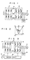
- Fig. 1 The circuit of Fig. 1 is based on natural commutation. This approach, however, still entails many problems which require to be solved.
- reference numeral 11 denotes an input terminal for the AC power source; 12, a rectifier; 13, a DC reactor; 14, an inverter circuit; 15, an induction motor serving as an inductive load; 16, a capacitive load such as a capacitor; 142, a thyristor.
- the AC power supplied from input terminal 11 for the AC power source is converted into DC power by rectifier 12.
- the converted DC power is smoothed by DC reactor 13.
- Inverter circuit 14 converts the smoothed DC power back into AC power, and supplies it to induction motor 15 and capacitive load 16.
- the relation of the currents of induction motor 15 and capacitive load 16 is illustrated in Fig. 2.
- load current IM of induction motor 15 contains active current component IP and delayed reactive current component II with power factor angle ⁇ 1.
- Current IC of capacitive load 16 is an advanced reactive current component. Therefore, if advanced reactive current component IC is larger than delayed reactive current component IL, inverter 14 supplies current II with advanced power factor angle ⁇ 2, as is shown in Fig. 4.
- inverter 14 When inverter 14 is operating to supply advanced current II and power factor ⁇ 2, at the commercial power supply frequency band (50 to 60 Hz), is in the range from 10° to 20°, even if thyristors are used for switching the elements in the arms of inverter circuit 14, these thyristors can be load-commutated or commutated in a natural manner.
- induction motor 15 If it is possible to operate induction motor 15 in a speed-controllable manner while thyristors 142 of inverter circuit 14 are load-commutated, the operating efficiency of the inverter circuit is remarkably improved as compared to that obtained when induction motor 15 operates at a variable speed during the forced commutation of inverter circuit 14. If the motor is operated in the above manner, the circuit arrangement of inverter 14 can be made simple, so that the circuit design of the inverter for high voltage operation becomes easy. Although a synchronous motor may be used as the motor serving as the load, an induction motor will be used in the following description.
- circuit system of Fig. 1 has the advantageous features as mentioned above, but still has problems, which will be described below.
- the current IC of capacitive load 16 is given as: current IC ⁇ (Inverter output frequency)2.
- a self-extinguishing element such as a gate turn-off thyristor (GTO) is inserted in each arm of the inverter.
- a capacitive load is connected to the output terminal of the inverter. In a region where the output frequency of the inverter is low, the self-extinguishing element is forced to be commutated. In a high-frequency region where the output frequency of the inverter is higher than in the low-frequency region, the capacitive load causes the self-extinguishing element to be load-commutated.
- FIG. 3 An embodiment of this invention is shown in Fig. 3.
- the circuit components designated by the same reference numerals as those in Fig. 1, have the same function as those components in Fig. 1.
- numeral 17 denotes a speed reference and 18 denotes a control circuit.
- Numerals 141 are self-extinguishing type power converter elements (e.g., GTOs).
- a snubber circuit (not shown in the drawing) is connected in parallel with each of elements 141.
- the AC power supplied from AC input terminal 11 is converted into DC power by rectifier 12.
- the converted DC power is smoothed by DC reactor 13.
- the smoothed DC power is inverted by inverter 14, and the resulting AC power is supplied to capacitive load 16 and induction motor 15.
- the speed of revolution of induction motor 15 is controlled, via control circuit 18, to be based on the set value of speed reference 17. Details of control circuit 18 will be described later, with reference to Fig. 4.
- inverter 14 which converts the DC power to AC power, performs forced commutation against self-extinguishing type converter elements 141, each constituting an arm of the bridge connection of inverter 14.
- delayed reactive current component IL of inductance motor 15 becomes greater than advanced reactive current component IC of capacitive load 16.
- inverter 14 supplies output current II with a delayed current phase.
- a commutation surge voltage caused by the forced commutation of self-extinguishing power converter elements 141, is suppressed by capacitive load 16.
- control circuit 18 fetches a signal (E183 in Fig. 4) that is synchronized with the output voltage of inverter 14. Then, it outputs gate signals to start the load commutation.
- output current II of inverter 14 is advanced in phase, since no commutation surge voltage appears, the capacity of the snubber circuits for absorbing the surge voltage of self-extinguishing power converter elements 141 can be reduced.
- the capacity of capacitive load 16 can be smaller than that of conventional devices.
- the required output capacity of inverter 14 can be reduced.
- the capacity of the snubber circuits of self-extinguishing power converter elements 141 can be made smaller (made to have smaller loss), and the operating efficiency can be improved.
- Control circuit 18 of Fig. 3 can be constructed as shown in Fig. 4.
- the control circuit of Fig. 4 is designed to control the ratio (V/F) of the output voltage to the output frequency of inverter 14 to a constant value, based on the set value of speed reference 17. More specifically, speed reference 17 applies set value E17 to ramp function circuit 181.
- Circuit 181 generates an output frequency reference E181 having a fixed rate of level-change to be based on set value E17.
- Reference E181 is applied to the positive phase input of adder 182.
- Voltage signal E183 corresponding to the AC output voltage of inverter 14, is applied to the anti-phase input of adder 182, via potential transformer 183.
- Adder 182 supplies difference E182, between reference E181 and signal E183, to voltage-control amplifier 184.
- Output E184 (output current reference) of amplifier 184 is applied to the positive phase input of adder 185.
- Current signal E186 corresponding to the DC input current of rectifier 12, is applied from current transformer 186 to the anti-phase input of adder 185.
- Adder 185 supplies difference E185, between output E184 and signal E186, to current control amplifier 187.
- Output E187 of amplifier 187 is applied to phase controller 188.
- Controller 188 controls rectifier 12, such that the input current of rectifier 12 is rendered to be equal to output current reference E184. Controller 188 also controls rectifier 12, so that the output voltage of inverter 14 corresponds to output frequency reference E181.
- Output frequency reference E181 is input to voltage-controlled oscillator (VCO) 189.
- VCO 189 generates pulse signal E189 having a frequency corresponding to the level of reference E181.
- Pulse signal E189 is input to pulse generator 190, details of which will be described later with reference to Fig. 5.
- circuit 190 According to pulse signal E189, circuit 190 generates twelve sets of 6-phase pulses E190, shown in Figs. 6G to 6R (used for GTO 141 and thyristor 142 in Fig. 8); or it generates six sets of 6-phase pulses E190, shown in Figs. 6G, 6I, 6K, 6M, 6O, and 6Q (used for GTO 141 in Fig. 3). Pulses E190 are applied to inverter 14 via pulse amplifier 191.
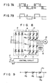
- Fig. 5 shows an example of the internal configuration of pulse generator 190.
- Pulse signal E189 from VCO 189 is input, as a clock signal, to 6-bit ring counter circuit 1900.
- Counter circuit 1900 generates six pulses E1900U, E1900Z, E1900V, E1900X, E1900W, and E1900Y. The phase of each pulse is shifted by 60° from that of the preceding pulse (see Figs. 6A to 6F). These six pulses are respectively input to pulse generators 190U to 190Z.
- the internal configuration of pulse generators 190U to 190Z is the same, so only the configuration of pulse generator 190U will be described in detail below.
- Pulse E1900U from ring counter circuit 1900 is input to delay circuit 1901 in U-phase pulse generator 190U.
- Delay output E1901 from circuit 1901 and pulse E1900U are input to AND gate 1902.
- the output of AND gate 1902 (Fig. 6H) becomes the pulse which turns on U-phase thyristor 142 of inverter 14.
- One shot 1903 is triggered by the trailing edge of pulse E1900U.
- One shot 1903 then generates pulse E1903 having a fixed pulse width.
- Pulse E1903 is input to the first input of AND gate 1904.
- Output E1905 of comparator 1905 is applied to the second input of AND gate 1904.
- AND gate 1904 passes pulse E1903, and AND output E1904 corresponding to E1903 is input to linear amplifier 1906.
- Linear amplifier 1906 is activated by negative power supply -Vss.
- the amplitude of E1906 corresponds to that of E1904.
- Negative OFF pulse E1906 is superposed by adder 1907 onto the trailing edge of positive ON pulse E1900U.
- the resulting signal from adder 1907 is used for forcibly commutating U-phase GTO 141 of inverter 14 (Fig. 6G).
- Comparator 1905 compares, with predetermined reference level Vref, the signal level of output frequency reference E181 from ramp function circuit 181.
- Reference level Vref defines the boundary of frequency reference E181 at which inverter 14 switches from forced commutation to load commutation. This boundary frequency is chosen so that the power factor of the inverter output current will have a value of almost 1.
- comparison output E1905 is at a high level.
- negative OFF pulse E1906 is added to gate control pulse E190 for GTO 141, so that forced commutation occurs.
- the level of comparison output E1905 is low.
- inverter 14 can be made to perform load commutation without reducing E1906 to zero, if the generation timing of E1906 is delayed for more than a certain time behind the trailing edge of E1900U.
- control circuit 18 can control inverter 14 by a forced commutation function or by a natural commutation function.
- Element 141 is a self-extinguishing type (e.g., a GTO).
- Element 142 is a natural-commutation type thyristor whose conduction-start timing is controllable.
- inverter 14 When set value E17 of speed reference 17 is in the low-output frequency range (E181 ⁇ Vref), inverter 14 is controlled with the forced commutation of self-extinguishing semiconductor element 141. At this time, a commutation surge voltage is produced by the forced commutation of self-extinguishing semiconductor element 141. During the initial stage of the forced commutation, most of the commutation surge voltage is applied to self-extinguishing semiconductor element 141. Then, after the natural commutation is performed, a part of the surge voltage is applied to natural-commutation semiconductor element 142.
- advanced reactive current component IC of capacitive load 16 is used by inverter 14. Because of this, the output power factor of output current II of inverter 14 crosses a boundary point near the power factor 1, and the phase of current II changes from a delayed-phase to an advanced-phase. This advanced-phase causes a natural commutation to be performed in natural-commutation semiconductor element 142. Then, it causes a forced commutation to be performed in self-extinguishing semiconductor element 141.
- the characteristics and type of the self-extinguishing semiconductor element 141 are not limited to the particular ones described herein.
- the circuit of one arm of inverter 14 can be made of two natural-commutation type semiconductor elements 142 and one self-extinguishing semiconductor element 141 connected in series to elements 142.
- the reverse voltage rating of self-extinguishing semiconductor element 141 is extremely small, if diode 143, anti-parallel connected to element 141, is provided, all the reverse voltage applied to this arm can be divided by two natural-commutation semiconductor elements 142.
- the turn-on loss of self-extinguishing semiconductor 141 is generally large. As a means for reducing this turn-on loss, if the conduction start time of natural-commutation semiconductor element 142 is delayed behind that of self-extinguishing semiconductor element 141, the turn-on loss will be reduced.
- the delay of the conduction start time can be accomplished by controlling the application timing of gate signals (cf. the leading edges of pulses of Figs. 6G and 6H).
- the self-extinguishing type power converter element is not limited only to a gate turn-off thyristor (GTO). It is evident that various kinds of elements, such as electrostatic induction thyristors, can be adapted.
- GTO gate turn-off thyristor
- the output current waveform of inverter 14 is not limited in this invention.
- pulse-width control (as shown in Fig. 7A) can be used, while in the intermediate-, or high-output frequency range, 120° square wave control (as shown in Fig. 7B) can be used.
- self-extinguishing power converter element 141 can be controlled to be self-extinguished at about the time when the current-overlapping of a load commutation disappears. If controlled in this way, power factor angle ⁇ 2 of the inverter output current can be made smaller, and the required output capacity of inverter 14 can be reduced even further.
- a capacitive load is connected to the output side of the inverter that drives the induction motor.
- the inverter is comprised of self-extinguishing power converter elements.
- the self-extinguishing power converter element is subjected to a forced commutation.
- a load commutation is performed.
Landscapes
- Engineering & Computer Science (AREA)
- Power Engineering (AREA)
- Inverter Devices (AREA)
Claims (10)
- Procédé de commande destiné à commander de façon variable la vitesse d'un moteur à courant alternatif (15) servant de charge inductive, grâce à l'utilisation d'un convertisseur de fréquence qui est constitué par un redresseur (12), une bobine de réactance en courant continu (13) et un onduleur (14) connecté à une charge capacitive (16), consistant essentiellement :
à commuter à force des éléments de commutation (14₁) constituant ledit onduleur (14) quand la fréquence de sortie dudit inverseur est inférieure à une valeur prédéterminée (Vref de la figure 5) ; et
à commuter par charge lesdits éléments de commutation (14₁) quand la fréquence de sortie de l'onduleur est supérieure à ladite valeur prédéterminée (Vref). - Procédé de commande selon la revendication 1, caractérisé en ce que ladite valeur prédéterminée (Vref) correspond à la fréquence de sortie de l'onduleur à laquelle le facteur de puissance du courant de sortie dudit onduleur (14) est environ l'unité.
- Procédé de commande selon la revendication 1, caractérisé en ce que chacun desdits éléments de commutation comporte un élément à auto-blocage (14₁).
- Procédé de commande selon la revendication 3, caractérisé en ce que lesdits éléments de commutation comportent en outre des éléments de commutation à commutation naturelle (14₂) connectés respectivement en série avec lesdits éléments de commutation à autoblocage (14₁).
- Appareil de commande destiné à commander de façon variable la vitesse d'un moteur à courant alternatif (15) servant de charge inductive grâce à l'utilisation d'un convertisseur de fréquence constitué par un redresseur (12), une bobine de réactance en courant continu (13) et un onduleur (14) connecté à une charge capacitive (16), comportant :
un dispositif de détection de fréquence de sortie (1905 sur la figure 5), pour détecter si la fréquence de sortie dudit onduleur est supérieure ou non à une valeur prédéterminée (Vref) ;
un dispositif de commutation forcée (1900, 1903, 1906, 1907) couplé avec ledit dispositif de détection de fréquence de sortie (1905) pour commuter à force les éléments de commutation (14₁) constituant ledit onduleur (14) quand ladite fréquence de sortie est inférieure à ladite valeur prédéterminée (Vref) ; et
un dispositif de commutation par charge (1900, 1904, 1907), couplé avec le dispositif de détection de fréquence de sortie (1905) pour commuter par charge lesdits éléments de commutation (14₁) quand ladite fréquence de sortie est supérieure à ladite valeur prédéterminée (Vref). - Appareil de commande selon la revendication 5, caractérisé en ce que ladite valeur prédéterminée (Vref) correspond à la fréquence de sortie de l'onduleur à laquelle le facteur de puissance du courant de sortie dudit onduleur (14) est à peu près unitaire.
- Appareil de commande selon la revendication 5, caractérisé en ce que chacun desdits éléments de commutation comporte un élément à auto-blocage (14₁).
- Appareil de commande selon la revendication 7, caractérisé en ce que lesdits éléments de commutation comportent en outre des éléments de commutation à commutation naturelle (14₂) connectés respectivement en série avec lesdits éléments de commutation à autoblocage (14₁).
- Appareil de commande selon la revendication 8, caractérisé en ce qu'il comporte en outre :
un dispositif (1901, 1902) couplé avec ledit dispositif de commutation forcée (1900) et le dispositif de commutation par charge (1900) pour débloquer ledit élément de commutation à commutation naturelle (14₂) après que se soit écoulée une période prédéterminée depuis le déblocage desdits éléments de commutation à auto-blocage (14₁). - Appareil de commande selon la revendication 9, caractérisé en ce que ledit élément de commutation à auto-blocage (14₁) est un thyristor à blocage par grille et ledit élément de commutation à commutation naturelle (14₂) est un thyristor.
Applications Claiming Priority (4)
| Application Number | Priority Date | Filing Date | Title |
|---|---|---|---|
| JP60223456A JPS6285691A (ja) | 1985-10-09 | 1985-10-09 | 交流電動機の制御装置 |
| JP60223455A JPS6285693A (ja) | 1985-10-09 | 1985-10-09 | 誘導電動機の制御方法 |
| JP223456/85 | 1985-10-09 | ||
| JP223455/85 | 1985-10-09 |
Publications (2)
| Publication Number | Publication Date |
|---|---|
| EP0218983A1 EP0218983A1 (fr) | 1987-04-22 |
| EP0218983B1 true EP0218983B1 (fr) | 1991-11-13 |
Family
ID=26525486
Family Applications (1)
| Application Number | Title | Priority Date | Filing Date |
|---|---|---|---|
| EP86113425A Expired - Lifetime EP0218983B1 (fr) | 1985-10-09 | 1986-09-30 | Méthode pour commander un moteur à courant alternatif et son appareil de commande |
Country Status (3)
| Country | Link |
|---|---|
| US (1) | US4736148A (fr) |
| EP (1) | EP0218983B1 (fr) |
| DE (1) | DE3682477D1 (fr) |
Families Citing this family (19)
| Publication number | Priority date | Publication date | Assignee | Title |
|---|---|---|---|---|
| US5123080A (en) * | 1987-03-20 | 1992-06-16 | Ranco Incorporated Of Delaware | Compressor drive system |
| JPH01160393A (ja) * | 1987-12-17 | 1989-06-23 | Fanuc Ltd | 3相誘導電動機の結線切換装置 |
| JPH01164294A (ja) * | 1987-12-19 | 1989-06-28 | Fanuc Ltd | 工作機械のスピンドル駆動制御装置 |
| US5010287A (en) * | 1988-02-24 | 1991-04-23 | Matsushita Electric Works, Ltd. | Induction motor control system |
| DE3942710A1 (de) * | 1989-12-22 | 1991-06-27 | Bosch Siemens Hausgeraete | Verfahren und schaltungsaufbau zur ansteuerung von mehreren triacs |
| US5126642A (en) * | 1991-01-31 | 1992-06-30 | Ranco Incorporated Of Delaware | Variable speed motor control |
| US5463300A (en) * | 1993-08-26 | 1995-10-31 | Oximberg; Carol A. | AC motor controller with 180 degree conductive switches |
| US5483140A (en) * | 1993-10-01 | 1996-01-09 | Wisconsin Alumni Research Foundation | Thyristor based DC link current source power conversion system for motor driven operation |
| US5629590A (en) * | 1993-10-19 | 1997-05-13 | Futaba Denshi Kogyo Kabushiki Kaisha | Rotational drive control device for variable speed drive motor |
| JPH07298627A (ja) * | 1994-04-27 | 1995-11-10 | Toshiba Corp | 電力変換器の制御装置 |
| DE19726161A1 (de) * | 1997-06-20 | 1998-12-24 | Alsthom Cge Alcatel | Verfahren zum Betrieb parallel geschalteter Stromzwischenkreisumrichter zur Speisung eines Asynchronmotor und dazugehörige Schaltungsanordnung |
| TW364049B (en) * | 1997-09-24 | 1999-07-11 | Toshiba Corp | Power conversion apparatus and air conditioner using the same |
| JP2000139085A (ja) * | 1998-08-24 | 2000-05-16 | Shibafu Engineering Kk | 電力変換装置 |
| US6717383B1 (en) * | 2000-08-30 | 2004-04-06 | Chris S. Brunt | Fountain control for generating dynamically changing flow patterns |
| US6989650B2 (en) * | 2003-09-11 | 2006-01-24 | Oilfield-Electric-Marine, Inc. | AC motor control system using parallel integrated sub systems |
| US7345449B2 (en) * | 2005-08-29 | 2008-03-18 | Benshaw, Inc. | Method of rotating a polyphase motor at less than rated speed |
| US7696715B2 (en) * | 2006-09-26 | 2010-04-13 | The Boeing Company | Power control for induction motors using variable frequency AC power |
| EP2773032A1 (fr) | 2013-03-01 | 2014-09-03 | GE Energy Power Conversion Technology Ltd | Convertisseur alimenté par une source de courant imposé avec des composants blocable et une commutation spéciale |
| FR3087614B1 (fr) * | 2018-10-19 | 2020-10-09 | Sagemcom Energy & Telecom Sas | Carte electrique comprenant un pont de redressement |
Family Cites Families (8)
| Publication number | Priority date | Publication date | Assignee | Title |
|---|---|---|---|---|
| US4131937A (en) * | 1976-05-14 | 1978-12-26 | Electric Power Research Institute, Inc. | Naturally commutated voltage-fed converter for linking a DC source to an AC system |
| US4288732A (en) * | 1978-11-30 | 1981-09-08 | General Electric Company | Forced commutated starting circuit for load commutated inverter drive system |
| JPS5594583A (en) * | 1979-01-10 | 1980-07-18 | Hitachi Ltd | Frequency converter and its controlling method |
| US4427933A (en) * | 1981-10-30 | 1984-01-24 | Westinghouse Electric Corp. | Load commutated inverter gating control system and motor drive with such control system |
| JPS58222786A (ja) * | 1982-06-18 | 1983-12-24 | Hitachi Ltd | 電流形インバ−タ装置の制御法 |
| JPS5956873A (ja) * | 1982-09-22 | 1984-04-02 | Toshiba Corp | エネルギ−転送装置 |
| US4511835A (en) * | 1982-12-23 | 1985-04-16 | Borg-Warner Corporation | Voltage-controlled, inverter-motor system |
| CA1224245A (fr) * | 1984-03-02 | 1987-07-14 | Suzuo Saito | Convertisseur d'alimentation pour charge a courant alternatif |
-
1986
- 1986-09-30 DE DE8686113425T patent/DE3682477D1/de not_active Expired - Lifetime
- 1986-09-30 EP EP86113425A patent/EP0218983B1/fr not_active Expired - Lifetime
- 1986-10-02 US US06/914,273 patent/US4736148A/en not_active Expired - Fee Related
Non-Patent Citations (3)
| Title |
|---|
| "A New Current Source GTO Inverter with Sinusoidal Output Voltage and Current", 1984, IEEEE, CH 2060/2/84/0000-0807$01.00, pp.807-812 * |
| J.D. Warwick, et al.: "A Variable Frequency Drive for Existing Medium Voltage Induction Motors", Proceedings of the American Power Conference, held on April 22-24, 1985; * |
| Siemens-Zeitschrift, Vol. 43, August 1969, No. 8, pp. 686-690; * |
Also Published As
| Publication number | Publication date |
|---|---|
| EP0218983A1 (fr) | 1987-04-22 |
| US4736148A (en) | 1988-04-05 |
| DE3682477D1 (de) | 1991-12-19 |
Similar Documents
| Publication | Publication Date | Title |
|---|---|---|
| EP0218983B1 (fr) | Méthode pour commander un moteur à courant alternatif et son appareil de commande | |
| US4730242A (en) | Static power conversion and apparatus having essentially zero switching losses | |
| US5483140A (en) | Thyristor based DC link current source power conversion system for motor driven operation | |
| US4934822A (en) | PWM-controlled power supply capable of eliminating modulation-frequency signal components from ground potentials | |
| US4489371A (en) | Synthesized sine-wave static generator | |
| Iimori et al. | New current-controlled PWM rectifier-voltage source inverter without DC link components | |
| Green et al. | Implementation of pulsewidth modulated inverter modulation strategies | |
| Joos et al. | A high performance current source inverter | |
| CA2218738C (fr) | Procede de traitement d'ondes pwm et dispositifs appliquant ce procede | |
| Ishikawa et al. | A novel soft-switched PWM current source inverter with voltage clamped circuit | |
| US5187652A (en) | Turn-off circuit | |
| KR900003483B1 (ko) | 전력 변환장치 | |
| US11757374B2 (en) | Method and apparatus for generating a three-phase voltage | |
| JP2001016857A (ja) | 電力変換装置 | |
| Cho et al. | A new current source inverter with simultaneous recovery and commutation | |
| JPH09233823A (ja) | 交流−直流変換器およびその制御装置 | |
| Rajashekara et al. | Resonant dc link inverter-fed ac machines control | |
| Pomilio et al. | Performance improvement of soft-switched PWM rectifiers with inductive load | |
| JP2549101B2 (ja) | 電力変換装置 | |
| FI20195164A1 (en) | Inverters | |
| CA1293021C (fr) | Methode et appareil de conversion statique de tension | |
| US20240429832A1 (en) | Power converter system | |
| Dewan et al. | The load-independent commutated voltage source inverter for induction heating | |
| KR890000971B1 (ko) | 전력변환 장치 | |
| JPH09312978A (ja) | 直流−交流電流形変換器の制御装置 |
Legal Events
| Date | Code | Title | Description |
|---|---|---|---|
| PUAI | Public reference made under article 153(3) epc to a published international application that has entered the european phase |
Free format text: ORIGINAL CODE: 0009012 |
|
| 17P | Request for examination filed |
Effective date: 19860930 |
|
| AK | Designated contracting states |
Kind code of ref document: A1 Designated state(s): CH DE FR GB LI SE |
|
| 17Q | First examination report despatched |
Effective date: 19890920 |
|
| GRAA | (expected) grant |
Free format text: ORIGINAL CODE: 0009210 |
|
| AK | Designated contracting states |
Kind code of ref document: B1 Designated state(s): CH DE FR GB LI SE |
|
| REF | Corresponds to: |
Ref document number: 3682477 Country of ref document: DE Date of ref document: 19911219 |
|
| ET | Fr: translation filed | ||
| PLBI | Opposition filed |
Free format text: ORIGINAL CODE: 0009260 |
|
| 26 | Opposition filed |
Opponent name: SIEMENS AG GR PA 2 ERL S Effective date: 19920720 |
|
| PLAB | Opposition data, opponent's data or that of the opponent's representative modified |
Free format text: ORIGINAL CODE: 0009299OPPO |
|
| R26 | Opposition filed (corrected) |
Opponent name: SIEMENS AKTIENGESELLSCHAFT, BERLIN UND MUENCHEN Effective date: 19920720 |
|
| PGFP | Annual fee paid to national office [announced via postgrant information from national office to epo] |
Ref country code: GB Payment date: 19940920 Year of fee payment: 9 |
|
| PGFP | Annual fee paid to national office [announced via postgrant information from national office to epo] |
Ref country code: CH Payment date: 19940923 Year of fee payment: 9 |
|
| EAL | Se: european patent in force in sweden |
Ref document number: 86113425.2 |
|
| PGFP | Annual fee paid to national office [announced via postgrant information from national office to epo] |
Ref country code: FR Payment date: 19950911 Year of fee payment: 10 |
|
| PGFP | Annual fee paid to national office [announced via postgrant information from national office to epo] |
Ref country code: SE Payment date: 19950918 Year of fee payment: 10 |
|
| PGFP | Annual fee paid to national office [announced via postgrant information from national office to epo] |
Ref country code: DE Payment date: 19950928 Year of fee payment: 10 |
|
| RDAG | Patent revoked |
Free format text: ORIGINAL CODE: 0009271 |
|
| STAA | Information on the status of an ep patent application or granted ep patent |
Free format text: STATUS: PATENT REVOKED |
|
| 27W | Patent revoked |
Effective date: 19951019 |
|
| GBPR | Gb: patent revoked under art. 102 of the ep convention designating the uk as contracting state |
Free format text: 951019 |
|
| REG | Reference to a national code |
Ref country code: CH Ref legal event code: PL |