EP0215486A2 - Farbbildröhre - Google Patents
Farbbildröhre Download PDFInfo
- Publication number
- EP0215486A2 EP0215486A2 EP86112910A EP86112910A EP0215486A2 EP 0215486 A2 EP0215486 A2 EP 0215486A2 EP 86112910 A EP86112910 A EP 86112910A EP 86112910 A EP86112910 A EP 86112910A EP 0215486 A2 EP0215486 A2 EP 0215486A2
- Authority
- EP
- European Patent Office
- Prior art keywords
- pins
- holding members
- picture tube
- color picture
- edge
- Prior art date
- Legal status (The legal status is an assumption and is not a legal conclusion. Google has not performed a legal analysis and makes no representation as to the accuracy of the status listed.)
- Granted
Links
Images
Classifications
-
- H—ELECTRICITY
- H01—ELECTRIC ELEMENTS
- H01J—ELECTRIC DISCHARGE TUBES OR DISCHARGE LAMPS
- H01J29/00—Details of cathode-ray tubes or of electron-beam tubes of the types covered by group H01J31/00
- H01J29/02—Electrodes; Screens; Mounting, supporting, spacing or insulating thereof
- H01J29/06—Screens for shielding; Masks interposed in the electron stream
- H01J29/07—Shadow masks for colour television tubes
- H01J29/073—Mounting arrangements associated with shadow masks
Definitions
- the invention relates to a color picture tube according to the preamble of claim 1.
- the invention has for its object to provide a simpler securing the holding members on the pins for such a color picture tube.
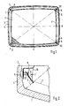
- Fig. 1 only the screen trough 1 with the shadow mask 2 is shown from a conventional color picture tube.
- the x-axis, the y-axis and the diagonals D1 and D2 are shown in this representation.
- the fritting surface on the edge 4 of the screen trough 1 is labeled 3.
- the screen trough 1 carries the luminescent layer, not shown, on its inside.
- pins 5 are arranged which support the shadow mask 2 via holding members 6.
- the holding members 6 engage on the edge 7 of the shadow mask 2.
- the axis of symmetry of the color picture tube is perpendicular to the plane of the drawing at the intersection of the x-axis with the y-axis.
- the shadow mask does not have to be held in the corners of the screen trough 1, but can also be provided at the intersections of the x and y axes with the edge 7 of the shadow mask 2 and the edge 4 of the screen trough 1.
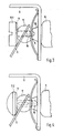
- FIG. 2 A section through the lower left corner of the screen trough 1 in FIG. 1 is shown in FIG. 2.
- the pin 5 is melted at one end.
- the pin 5 is inserted into the edge 4 so that it is perpendicular to the axis of symmetry of the color picture tube.
- a different orientation of the pins is also possible.
- the free end of the pin 5 carries the two-part holding member 6, which is connected to the edge 7 of the shadow mask 2 on the outside via a corner reinforcement 8.
- the holding member 6 is aligned so that it is perpendicular to the electrode beam E directed into this corner.
- the pin 5 also carries a bracket 9, at the free end of which the magnetic shield 10 of the color picture tube is attached.
- a securing element 11 is introduced, which presses the free end of the holding member 6 onto the pin 5.
- the same reference numerals have also been used for the same parts.
- the diameter of the spherical end 12 is larger than the smaller diameter of the conical part 13, so that a constriction 14 is formed between the conical part 13 and the spherical end 12.
- On the spherical end 12 is the holding member 6, which is held in place by the securing element 11.
- Other designs of the free ends of the pins are also possible, e.g. a conical shape.
- the securing element 11 consists in this embodiment example of a cap screw 11.1.
- This cap screw 11.1 is in a threaded blind hole 15 in screwed free end of pin 5.
- the edge of the head of the cap screw 11.1 comes into contact with the holding member 6 and presses it onto the spherical end 12 of the pin 5.
- This edge of the cap screw is chamfered at such an angle that the resulting surface 17 runs parallel to the surface of the holding member 6 .
- the second exemplary embodiment for the securing element 11 shown in FIG. 4 consists of a notch nail 11.2.
- the notch 11.2 is pressed into a blind hole 16 present in the free end 12 of the pin 5.
- the head of the notch nail 11.2 presses on the holding member 6 and holds it on the spherical end 12 of the pin 5.
- the edge of the head of the notch nail 11.2 in contact with the holding member 6 is chamfered at such an angle that the resulting surface 17 is parallel runs to the surface of the holding member 6.
- the securing element 11 ensures simple and inexpensive securing of the holding members against unhooking. This type of protection is less susceptible to overload than safety springs. The pressure forces generated also show smaller fluctuations in comparison with one another.
Landscapes
- Electrodes For Cathode-Ray Tubes (AREA)
Abstract
Description
- Die Erfindung bezieht sich auf eine Farbbildröhre gemäß dem Oberbegriff des Anspruchs 1.
- Aus der DE-A1 31 25 095 ist eine Farbbildröhre bekannt, deren Stifte zum Tragen der Schattenmaske unter einem derartigen Winkel in dem Rand der Schirmwanne eingeschmolzen sind, daß ihre Längsachsen parallel zum zur betreffenden Ecke abgelenkten Elektronenstrahl verlaufen. Die freien Enden der Stifte sind kegelig ausgebildet und die Halteglieder sind länglich und einstückig. Zur Sicherung der Halteglieder auf den Stiften werden aus zwei Teilen bestehende Klemmglieder benutzt.
- Der Erfindung liegt die Aufgabe zugrunde, für eine derartige Farbbildröhre eine einfachere Sicherung der Halteglieder auf den Stiften anzugeben.
- Die Lösung dieser Aufggabe erfolgt mit den im Anspruch 1 genannten Mitteln. Vorteilhafte Ausgestaltunqen können den Ansprüchen 2 bis 4 entnommen werden.
- Die Erfindung wird nun anhand von vier Figuren aufweisenden Zeichnungen zweier Ausführungsbeispiele näher erläutert. Es zeigen:
- Fig. 1 die Draufsicht auf eine Schirmwanne mit einer eingesetzten Schattenmaske;
- Fig. 2 einen Schnitt durch eine Ecke der Schirmwanne;
- Fig. 3 eine vergrößerte Darstellung eines Teiles der Fig. 2 mit einer Kopfschraube als Sicherungselement und
- Fig. 4 das zweite Ausführungsbeispiel des Sicherungselementes.
- In Fig. 1 ist von einer üblichen Farbbildröhre nur die Schirmwanne 1 mit der eingesetzten Schattenmaske 2 dargestellt. Es sind in diese Darstellung die x-Achse, die y-Achse und die Diagonalen D1 und D2 eingezeichnet. Die Frittfläche auf dem Rand 4 der Schirmwanne 1 ist mit 3 bezeichnet. Die Schirmwanne 1 trägt auf ihrer Innenseite die nicht dargestellte Leuchtschicht. Im Schnittpunkt der Diagonalen D1 und D2 mit dem Rand 4 der Schirmwanne 1 sind Stifte 5 angeordnet, die über Halteglieder 6 die Schattenmaske 2 tragen. Die Halteglieder 6 greifen am Rand 7 der Schattenmaske 2 an.
- Die Symmetrieachse der Farbbildröhre steht im Schnittpunkt der x-Achse mit der y-Achse senkrecht auf der Zeichenebene. Die Halterung der Schattenmaske muß nicht in den Ecken der Schirmwanne 1 erfolgen, sondern kann auch in den Schnittpunkten der x- und der y-Achse mit dem Rand 7 der Schattenmaske 2 und dem Rand 4 der Schirmwanne 1 vorgesehen sein.
- Einen Schnitt durch die in Fig. 1 linken unteren Ecke der Schirmwanne 1 ist in Fig. 2 dargestellt. In den Rand 4 der Schirmwanne 1 ist der Stift 5 mit seinem einen Ende eingeschmolzen. Der Stift 5 ist so in den Rand 4 eingesetzt, daß er senkrecht zur Symmetrieachse der Farbbildröhre steht. Es ist aber auch eine andere Ausrichtung der Stifte möglich. Das freie Ende des Stiftes 5 trägt das zweiteilige Halteglied 6, das über eine Eckenverstärkung 8 außen mit dem Rand 7 der Schattenmaske 2 verbunden ist. Das Halteglied 6 ist so ausgerichtet, daß es senkrecht auf dem in diese Ecke gelenkten Elektrodenstrahl E steht. Der Stift 5 trägt weiterhin einen Haltewinkel 9, an dessen freiem Ende die magnetische Abschirmung 10 der Farbbildröhre befestigt ist. In das freie Ende 12 des Stiftes 5 ist ein Sicherungselement 11 eingebracht, das das freie Ende des Haltegliedes 6 auf den Stift 5 drückt.
- Bei der in Fig. 3 gezeigten vergrößerten Darstellung des Sicherungselementes 11 gemäß Fig. 2 sind für gleiche Teile auch gleiche Bezugszeichen verwendet worden. Der mit seinem einen Ende in den Rand der Schirmwanne eingeschmolzene Stift 5 geht nach dem Austritt aus dem Rand in ein konusförmiges Teil 13 über, das das kugelförmige Ende des Stiftes 5 trägt. Der Durchmesser des kugelförmigen Endes 12 ist dabei größer als der kleinere Durchmesser des konusförmigen Teiles 13, so daß zwischen dem konusförmigen Teil 13 und dem kugelförmigen Ende 12 eine Einschnürung 14 entsteht. Auf dem kugelförmigen Ende 12 liegt das Halteglied 6 auf, das durch das Sicherungselement 11 an diesem Ort gehalten wird. Es sind auch andere Ausbildungen der freien Enden der Stifte möglich, z.B. eine kegelförmige Gestaltung.
- Das Sicherungselement 11 besteht in diesem Ausführungs beispiel aus einer Kopfschraube 11.1. Diese Kopfschraube 11.1 ist in ein mit Gewinde versehenes Sackloch 15 im freien Ende des Stiftes 5 eingeschraubt. Dadurch kommt der Rand des Kopfes der Kopfschraube 11.1 mit dem Halteglied 6 in Berührung und drückt dieses auf das kugelförmige Ende 12 des Stiftes 5. Dieser Rand der Kopfschraube ist unter einem derartigen Winkel angefast, daß die entstandene Fläche 17 parallel zur Fläche des Haltegliedes 6 verläuft.
- Das in Fig. 4 dargestellte zweite Ausführungsbeispiel für das Sicherungselement 11 besteht aus einem Kerbnagel 11.2. Der Kerbnael 11.2 ist in ein im freien Ende 12 des Stiftes 5 vorhandenes Sackloch 16 eingepreßt. Dadurch drückt der Kopf des Kerbnagels 11.2 auf das Halteglied 6 und hält es auf dem kugelförmigen Ende 12 des Stiftes 5. Der mit dem Halteglied 6 in Berührung stehende Rand des Kopfes des Kerbnagels 11.2 ist unter einem derartigen Winkel angefast, daß die entstandene Fläche 17 parallel zur Fläche des Haltegliedes 6 verläuft.
- Durch das erfindungsgemäße Sicherungselement 11 ist eine einfache und kostengünstige Sicherung der Halteglieder gegen Aushängen gewährleistet. Diese Art der Sicherung ist weniger anfällig gegen Uberlastung als Sicherungsfedern. Die erzeugten Druckkräfte weisen darüberhinaus in Vergleich miteinander geringere Schwankungen auf.
Claims (4)
Applications Claiming Priority (2)
| Application Number | Priority Date | Filing Date | Title |
|---|---|---|---|
| DE3533564 | 1985-09-20 | ||
| DE19853533564 DE3533564A1 (de) | 1985-09-20 | 1985-09-20 | Farbbildroehre |
Publications (3)
| Publication Number | Publication Date |
|---|---|
| EP0215486A2 true EP0215486A2 (de) | 1987-03-25 |
| EP0215486A3 EP0215486A3 (en) | 1987-12-23 |
| EP0215486B1 EP0215486B1 (de) | 1989-08-30 |
Family
ID=6281476
Family Applications (1)
| Application Number | Title | Priority Date | Filing Date |
|---|---|---|---|
| EP86112910A Expired EP0215486B1 (de) | 1985-09-20 | 1986-09-18 | Farbbildröhre |
Country Status (5)
| Country | Link |
|---|---|
| US (1) | US4730142A (de) |
| EP (1) | EP0215486B1 (de) |
| JP (1) | JPS6276138A (de) |
| CA (1) | CA1262472A (de) |
| DE (2) | DE3533564A1 (de) |
Families Citing this family (2)
| Publication number | Priority date | Publication date | Assignee | Title |
|---|---|---|---|---|
| US6518694B1 (en) | 1999-09-15 | 2003-02-11 | Osram Sylvania Inc. | Stud for cathode ray tube face panel |
| KR20020029873A (ko) * | 2000-05-02 | 2002-04-20 | 요트.게.아. 롤페즈 | 컬러 선택 전극의 개량된 서스펜션을 갖춘 컬러디스플레이 튜브 |
Family Cites Families (8)
| Publication number | Priority date | Publication date | Assignee | Title |
|---|---|---|---|---|
| US2899575A (en) * | 1959-08-11 | Glass-to-metal seals in cathode-ray tubes | ||
| US2899578A (en) * | 1954-05-10 | 1959-08-11 | Magnetic scanning circuits for cathode ray tubes | |
| US2922063A (en) * | 1956-11-07 | 1960-01-19 | Sylvania Electric Prod | Target assembly for cathode ray tubes |
| JPS439618Y1 (de) * | 1964-11-14 | 1968-04-26 | ||
| US3700949A (en) * | 1971-01-21 | 1972-10-24 | Nippon Electric Co | Color television picture tube |
| NL8004173A (nl) * | 1980-07-21 | 1982-02-16 | Philips Nv | Kleurenbeeldbuis. |
| US4506188A (en) * | 1982-11-24 | 1985-03-19 | North American Philips Consumer Electronics Corp. | Laminated metallic means for dampening internal CRT vibrations |
| DE3411330A1 (de) * | 1984-03-28 | 1985-10-10 | Standard Elektrik Lorenz Ag, 7000 Stuttgart | Farbbildroehre |
-
1985
- 1985-09-20 DE DE19853533564 patent/DE3533564A1/de not_active Withdrawn
-
1986
- 1986-09-12 CA CA000518054A patent/CA1262472A/en not_active Expired
- 1986-09-17 US US06/908,315 patent/US4730142A/en not_active Expired - Fee Related
- 1986-09-18 EP EP86112910A patent/EP0215486B1/de not_active Expired
- 1986-09-18 DE DE8686112910T patent/DE3665376D1/de not_active Expired
- 1986-09-19 JP JP61221744A patent/JPS6276138A/ja active Granted
Also Published As
| Publication number | Publication date |
|---|---|
| US4730142A (en) | 1988-03-08 |
| JPH0361978B2 (de) | 1991-09-24 |
| JPS6276138A (ja) | 1987-04-08 |
| DE3665376D1 (en) | 1989-10-05 |
| EP0215486A3 (en) | 1987-12-23 |
| DE3533564A1 (de) | 1987-03-26 |
| CA1262472A (en) | 1989-10-24 |
| EP0215486B1 (de) | 1989-08-30 |
Similar Documents
| Publication | Publication Date | Title |
|---|---|---|
| EP0156362B1 (de) | Farbbildröhre | |
| EP0687635A1 (de) | Flaschen- oder Kanisterverschluss | |
| DE2444699A1 (de) | Anschlussteil fuer eine in dickfilmtechnik ausgefuehrte kleinstbaueinheit | |
| EP0215486B1 (de) | Farbbildröhre | |
| EP0377874A1 (de) | Lötvorrichtung mit mindestens einer Bügelelektrode und zwei einander gegenüberliegenden Lötstegen oder vier paarweise einander gegenüberliegenden Lötstegen | |
| DD260365A5 (de) | Farbbildwiedergaberoehre | |
| EP0237881A1 (de) | Halterung fuer Pads zur Nasenauflage an Brillengestellen | |
| DE3520293C1 (de) | Messlupenanordnung | |
| DE8914460U1 (de) | Kontaktelement zum Anschluß von Litzenleitern | |
| DE3884920T2 (de) | Farbfernsehbildröhre. | |
| DE2525640A1 (de) | Elektrischer kontaktstift | |
| EP0235724A1 (de) | Farbbildröhre | |
| DE1915483A1 (de) | Befestigungsvorrichtung mit Hilfe eines Saugnapfes | |
| DE3233621C1 (de) | Abschirmgehäuse mit einem aufsetzbaren Deckel und/oder aufsetzbaren Boden | |
| DE1811045B2 (de) | Abgleichbare schalenkernspule fuer gedruckte schaltungen | |
| DE69114894T2 (de) | Elektronenstrahlröhre mit Elektronenstrahlerzeugungssystem. | |
| DE4231326A1 (de) | Druckerfassungschip fuer einen halbleiterdruckdetektor | |
| DE10206756B4 (de) | Schalt-Federkontaktstift | |
| EP0180040A2 (de) | Farbbildröhre | |
| EP0172547A1 (de) | Dübel | |
| DE1088187B (de) | Zahnprothese | |
| DE4337861A1 (de) | Modulare keilförmige Halteelemente | |
| DE2812422C2 (de) | ||
| DE3744684A1 (de) | Bezeichnungsschilder-traeger fuer ein steckverbindergehaeuse | |
| DE29704161U1 (de) | Kontaktelement |
Legal Events
| Date | Code | Title | Description |
|---|---|---|---|
| PUAI | Public reference made under article 153(3) epc to a published international application that has entered the european phase |
Free format text: ORIGINAL CODE: 0009012 |
|
| AK | Designated contracting states |
Kind code of ref document: A2 Designated state(s): DE FR GB IT NL |
|
| PUAL | Search report despatched |
Free format text: ORIGINAL CODE: 0009013 |
|
| AK | Designated contracting states |
Kind code of ref document: A3 Designated state(s): DE FR GB IT NL |
|
| 17P | Request for examination filed |
Effective date: 19880427 |
|
| RAP1 | Party data changed (applicant data changed or rights of an application transferred) |
Owner name: NOKIA GRAETZ GESELLSCHAFT MIT BESCHRAENKTER HAFTUN |
|
| 17Q | First examination report despatched |
Effective date: 19881117 |
|
| GRAA | (expected) grant |
Free format text: ORIGINAL CODE: 0009210 |
|
| AK | Designated contracting states |
Kind code of ref document: B1 Designated state(s): DE FR GB IT NL |
|
| ITF | It: translation for a ep patent filed | ||
| REF | Corresponds to: |
Ref document number: 3665376 Country of ref document: DE Date of ref document: 19891005 |
|
| GBT | Gb: translation of ep patent filed (gb section 77(6)(a)/1977) | ||
| ET | Fr: translation filed | ||
| RAP2 | Party data changed (patent owner data changed or rights of a patent transferred) |
Owner name: NOKIA UNTERHALTUNGSELEKTRONIK (DEUTSCHLAND) GMBH |
|
| NLT2 | Nl: modifications (of names), taken from the european patent patent bulletin |
Owner name: NOKIA UNTERHALTUNGSELEKTRONIK (DEUTSCHLAND) GMBH T |
|
| PLBE | No opposition filed within time limit |
Free format text: ORIGINAL CODE: 0009261 |
|
| STAA | Information on the status of an ep patent application or granted ep patent |
Free format text: STATUS: NO OPPOSITION FILED WITHIN TIME LIMIT |
|
| 26N | No opposition filed | ||
| REG | Reference to a national code |
Ref country code: FR Ref legal event code: CD |
|
| NLT1 | Nl: modifications of names registered in virtue of documents presented to the patent office pursuant to art. 16 a, paragraph 1 |
Owner name: NOKIA UNTERHALTUNGSELEKTRONIK (DEUTSCHLAND) GMBH T |
|
| ITPR | It: changes in ownership of a european patent |
Owner name: CAMBIO RAGIONE SOCIALE;NOKIA (DEUTSCHLAND) GMBH |
|
| REG | Reference to a national code |
Ref country code: FR Ref legal event code: CD |
|
| NLT1 | Nl: modifications of names registered in virtue of documents presented to the patent office pursuant to art. 16 a, paragraph 1 |
Owner name: NOKIA (DEUTSCHLAND) GMBH TE PFORZHEIM, BONDSREPUBL |
|
| PGFP | Annual fee paid to national office [announced via postgrant information from national office to epo] |
Ref country code: GB Payment date: 19930908 Year of fee payment: 8 |
|
| ITTA | It: last paid annual fee | ||
| PGFP | Annual fee paid to national office [announced via postgrant information from national office to epo] |
Ref country code: NL Payment date: 19930930 Year of fee payment: 8 |
|
| PGFP | Annual fee paid to national office [announced via postgrant information from national office to epo] |
Ref country code: DE Payment date: 19931112 Year of fee payment: 8 |
|
| PG25 | Lapsed in a contracting state [announced via postgrant information from national office to epo] |
Ref country code: GB Effective date: 19940918 |
|
| PGFP | Annual fee paid to national office [announced via postgrant information from national office to epo] |
Ref country code: FR Payment date: 19940927 Year of fee payment: 9 |
|
| PG25 | Lapsed in a contracting state [announced via postgrant information from national office to epo] |
Ref country code: NL Effective date: 19950401 |
|
| NLV4 | Nl: lapsed or anulled due to non-payment of the annual fee | ||
| GBPC | Gb: european patent ceased through non-payment of renewal fee |
Effective date: 19940918 |
|
| PG25 | Lapsed in a contracting state [announced via postgrant information from national office to epo] |
Ref country code: DE Effective date: 19950601 |
|
| PG25 | Lapsed in a contracting state [announced via postgrant information from national office to epo] |
Ref country code: FR Effective date: 19960531 |
|
| REG | Reference to a national code |
Ref country code: FR Ref legal event code: ST |
|
| PG25 | Lapsed in a contracting state [announced via postgrant information from national office to epo] |
Ref country code: IT Free format text: LAPSE BECAUSE OF NON-PAYMENT OF DUE FEES Effective date: 20050918 |