EP0215330B1 - Kombiniertes Gas- und Dampfturbinenkraftwerk - Google Patents
Kombiniertes Gas- und Dampfturbinenkraftwerk Download PDFInfo
- Publication number
- EP0215330B1 EP0215330B1 EP86111587A EP86111587A EP0215330B1 EP 0215330 B1 EP0215330 B1 EP 0215330B1 EP 86111587 A EP86111587 A EP 86111587A EP 86111587 A EP86111587 A EP 86111587A EP 0215330 B1 EP0215330 B1 EP 0215330B1
- Authority
- EP
- European Patent Office
- Prior art keywords
- gas
- coal
- plant
- drying
- power station
- Prior art date
- Legal status (The legal status is an assumption and is not a legal conclusion. Google has not performed a legal analysis and makes no representation as to the accuracy of the status listed.)
- Expired - Lifetime
Links
- 239000007789 gas Substances 0.000 claims abstract description 142
- 239000003245 coal Substances 0.000 claims abstract description 69
- 238000001035 drying Methods 0.000 claims abstract description 59
- 238000000926 separation method Methods 0.000 claims abstract description 20
- 238000010438 heat treatment Methods 0.000 claims abstract description 19
- 238000002485 combustion reaction Methods 0.000 claims abstract description 15
- QVGXLLKOCUKJST-UHFFFAOYSA-N atomic oxygen Chemical compound [O] QVGXLLKOCUKJST-UHFFFAOYSA-N 0.000 claims abstract description 11
- 229910052760 oxygen Inorganic materials 0.000 claims abstract description 11
- 239000001301 oxygen Substances 0.000 claims abstract description 11
- 238000011144 upstream manufacturing Methods 0.000 claims abstract description 8
- 239000002918 waste heat Substances 0.000 claims abstract description 7
- 239000011261 inert gas Substances 0.000 claims abstract description 6
- 238000002360 preparation method Methods 0.000 claims abstract description 6
- 239000002912 waste gas Substances 0.000 claims abstract 10
- 238000002156 mixing Methods 0.000 claims abstract 5
- 238000000746 purification Methods 0.000 claims abstract 3
- IJGRMHOSHXDMSA-UHFFFAOYSA-N Atomic nitrogen Chemical compound N#N IJGRMHOSHXDMSA-UHFFFAOYSA-N 0.000 claims description 30
- 229910052757 nitrogen Inorganic materials 0.000 claims description 15
- 239000000203 mixture Substances 0.000 claims description 3
- XLYOFNOQVPJJNP-UHFFFAOYSA-N water Substances O XLYOFNOQVPJJNP-UHFFFAOYSA-N 0.000 claims description 3
- 239000000567 combustion gas Substances 0.000 claims description 2
- 239000002737 fuel gas Substances 0.000 claims description 2
- 238000000227 grinding Methods 0.000 description 13
- RAHZWNYVWXNFOC-UHFFFAOYSA-N Sulphur dioxide Chemical compound O=S=O RAHZWNYVWXNFOC-UHFFFAOYSA-N 0.000 description 4
- 238000004140 cleaning Methods 0.000 description 4
- 239000000428 dust Substances 0.000 description 4
- 238000009434 installation Methods 0.000 description 4
- MWUXSHHQAYIFBG-UHFFFAOYSA-N Nitric oxide Chemical compound O=[N] MWUXSHHQAYIFBG-UHFFFAOYSA-N 0.000 description 3
- CURLTUGMZLYLDI-UHFFFAOYSA-N Carbon dioxide Chemical compound O=C=O CURLTUGMZLYLDI-UHFFFAOYSA-N 0.000 description 2
- 230000015572 biosynthetic process Effects 0.000 description 2
- 238000011161 development Methods 0.000 description 2
- 230000018109 developmental process Effects 0.000 description 2
- 239000000446 fuel Substances 0.000 description 2
- 239000000463 material Substances 0.000 description 2
- NINIDFKCEFEMDL-UHFFFAOYSA-N Sulfur Chemical compound [S] NINIDFKCEFEMDL-UHFFFAOYSA-N 0.000 description 1
- 230000000712 assembly Effects 0.000 description 1
- 238000000429 assembly Methods 0.000 description 1
- 229910002092 carbon dioxide Inorganic materials 0.000 description 1
- 239000001569 carbon dioxide Substances 0.000 description 1
- 230000006835 compression Effects 0.000 description 1
- 238000007906 compression Methods 0.000 description 1
- 230000006866 deterioration Effects 0.000 description 1
- 150000002366 halogen compounds Chemical class 0.000 description 1
- 230000001771 impaired effect Effects 0.000 description 1
- 239000012535 impurity Substances 0.000 description 1
- 238000000034 method Methods 0.000 description 1
- 238000003801 milling Methods 0.000 description 1
- 230000003647 oxidation Effects 0.000 description 1
- 238000007254 oxidation reaction Methods 0.000 description 1
- 238000011084 recovery Methods 0.000 description 1
- 238000010079 rubber tapping Methods 0.000 description 1
- 229910052717 sulfur Inorganic materials 0.000 description 1
- 239000011593 sulfur Substances 0.000 description 1
Images

Classifications
-
- F—MECHANICAL ENGINEERING; LIGHTING; HEATING; WEAPONS; BLASTING
- F01—MACHINES OR ENGINES IN GENERAL; ENGINE PLANTS IN GENERAL; STEAM ENGINES
- F01K—STEAM ENGINE PLANTS; STEAM ACCUMULATORS; ENGINE PLANTS NOT OTHERWISE PROVIDED FOR; ENGINES USING SPECIAL WORKING FLUIDS OR CYCLES
- F01K23/00—Plants characterised by more than one engine delivering power external to the plant, the engines being driven by different fluids
- F01K23/02—Plants characterised by more than one engine delivering power external to the plant, the engines being driven by different fluids the engine cycles being thermally coupled
- F01K23/06—Plants characterised by more than one engine delivering power external to the plant, the engines being driven by different fluids the engine cycles being thermally coupled combustion heat from one cycle heating the fluid in another cycle
- F01K23/067—Plants characterised by more than one engine delivering power external to the plant, the engines being driven by different fluids the engine cycles being thermally coupled combustion heat from one cycle heating the fluid in another cycle the combustion heat coming from a gasification or pyrolysis process, e.g. coal gasification
- F01K23/068—Plants characterised by more than one engine delivering power external to the plant, the engines being driven by different fluids the engine cycles being thermally coupled combustion heat from one cycle heating the fluid in another cycle the combustion heat coming from a gasification or pyrolysis process, e.g. coal gasification in combination with an oxygen producing plant, e.g. an air separation plant
-
- F—MECHANICAL ENGINEERING; LIGHTING; HEATING; WEAPONS; BLASTING
- F02—COMBUSTION ENGINES; HOT-GAS OR COMBUSTION-PRODUCT ENGINE PLANTS
- F02C—GAS-TURBINE PLANTS; AIR INTAKES FOR JET-PROPULSION PLANTS; CONTROLLING FUEL SUPPLY IN AIR-BREATHING JET-PROPULSION PLANTS
- F02C6/00—Plural gas-turbine plants; Combinations of gas-turbine plants with other apparatus; Adaptations of gas-turbine plants for special use
- F02C6/04—Gas-turbine plants providing heated or pressurised working fluid for other apparatus, e.g. without mechanical power output
- F02C6/10—Gas-turbine plants providing heated or pressurised working fluid for other apparatus, e.g. without mechanical power output supplying working fluid to a user, e.g. a chemical process, which returns working fluid to a turbine of the plant
-
- Y—GENERAL TAGGING OF NEW TECHNOLOGICAL DEVELOPMENTS; GENERAL TAGGING OF CROSS-SECTIONAL TECHNOLOGIES SPANNING OVER SEVERAL SECTIONS OF THE IPC; TECHNICAL SUBJECTS COVERED BY FORMER USPC CROSS-REFERENCE ART COLLECTIONS [XRACs] AND DIGESTS
- Y02—TECHNOLOGIES OR APPLICATIONS FOR MITIGATION OR ADAPTATION AGAINST CLIMATE CHANGE
- Y02E—REDUCTION OF GREENHOUSE GAS [GHG] EMISSIONS, RELATED TO ENERGY GENERATION, TRANSMISSION OR DISTRIBUTION
- Y02E20/00—Combustion technologies with mitigation potential
- Y02E20/16—Combined cycle power plant [CCPP], or combined cycle gas turbine [CCGT]
- Y02E20/18—Integrated gasification combined cycle [IGCC], e.g. combined with carbon capture and storage [CCS]
Definitions
- the invention relates to a combined gas and steam turbine power plant with a coal gasifier, with a coal preparation plant, with a coal mill and a drying device, with an air separation plant upstream of the coal gasifier, with a heat exchanger plant and gas cleaning plant downstream of the coal gasifier, with one leading to the combustion chamber of the gas turbine Clean gas line and a waste heat boiler connected to the exhaust gas line of the gas turbine, in which the sensible heat of the exhaust gas of the gas turbine is used to dry the ground coal.
- a combined gas and steam turbine power plant in which the combustion chamber of the gas turbine is fed with a clean gas which is previously generated in a coal gasifier assigned to the power plant.
- a coal gasifier assigned to the power plant.
- ground coal and, on the other hand, oxygen from an air separation plant are fed into the coal gasifier.
- the sensible heat of the raw gas leaving the coal gasifier is used via heat exchanger heating surfaces both for heating the clean gas flowing into the combustion chamber of the gas turbine and for generating steam.
- the nitrogen in the air separation unit is mixed with the clean gas flowing into the combustion chamber in order to reduce nitrogen oxide formation by lowering the flame temperature.
- the exhaust gas from the gas turbine is also passed through a heat recovery steam generator.
- the steam turbine of the steam turbine power plant is fed with the steam generated in these two heat exchangers.
- the invention has for its object to provide the drying energy for the milling and tracking system in a manner that does not generate additional sulfur dioxide emissions and moreover as little as possible deteriorates the net efficiency of the entire power plant. In addition, a fire hazard should be eliminated.
- nitrogen is added to the gas turbine exhaust gas from the air separation plant in an embodiment of the invention.
- a gas is used that is generated in the power plant anyway.
- the heating and drying medium can circulate as a so-called recycle gas through the grinding and drying system, partial quantities laden with moisture flowing out and being replaced by new heated heating and drying medium.
- a recirculation of the heating and drying medium can greatly reduce the consumption of the same.
- the coal can be dried by direct contact with an inert gas, the inert gas being conveyed as a so-called recycle gas circuit through a heat exchanger through which the heating medium flows to the grinding / drying system and back through the heat exchanger.
- an inert gas being conveyed as a so-called recycle gas circuit through a heat exchanger through which the heating medium flows to the grinding / drying system and back through the heat exchanger.
- the combined gas and steam turbine power plant 1 essentially consists of a gas turbine power plant part 2, a steam turbine power plant part 3, a coal gasifier 4 connected upstream of the gas turbine power plant part 2, with an air separation unit 5 connected upstream of the coal gasifier, a heat exchanger system 6 connected downstream of the coal gasifier, and a raw gas exchanger the gas cleaning system 7 downstream of the heat exchanger system on the raw gas side.
- the clean gas line 8 leaving the gas cleaning system 7 is guided via a raw gas / clean gas heat exchanger 9 of the heat exchanger system and connected to the combustion chamber 10 of the gas turbine 11.
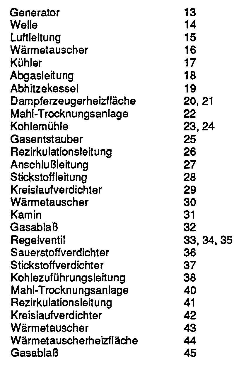
- An air compressor 12 and a generator 13 are coupled to the shaft 14 of the gas turbine 11.
- the air line 15 connected to the air compressor 12 leads both to the combustion chamber 10 of the gas turbine and via a heat exchanger 16 and a cooler 17 to the entrance of the air separation system 5.
- the exhaust line 18 of the gas turbine 11 leads through a waste heat boiler 19.
- the steam generator heating surfaces 20, 21 both Abhitzekesseis 19 and the heat exchanger system 6 are connected to the steam turbine power plant part 3 only indicated here.
- a grinding and drying installation 22 is connected upstream of the coal gasifier on the fuel side.
- This grinding and drying system which contains a number of coal mills 23, 24, a gas deduster 25 and a finished dust bunker (not shown), is flowed through by a circulating drying medium, the so-called recycle gas.
- Whose recirculation line 26 is connected via a connecting line 27 both to the exhaust line 18 of the gas turbine 11 and to the nitrogen line 28 of the air separation plant 5. It contains a circuit compressor 29 for circulating the drying medium.
- a heat exchanger through which a heating medium flows is installed in the nitrogen line 28 leading to the recirculation line 26.
- the heating medium flowing through this heat exchanger 30 can be raw gas branched off in front of the raw gas-pure gas heat exchanger or removed compressed air behind the air compressor 12 and flowing to the air separation plant 5.
- the recirculation line 26 contains a gas outlet 32 leading to the chimney 31. Both in the gas outlet 32 and in the nitrogen line 28 and in the connecting line 27 to the exhaust line 18 of the gas turbine 11 there are control valves 33, 34, 35 installed.
- this clean gas is admixed with nitrogen from the air separation plant 5 via a nitrogen compressor 37.
- the exhaust gas from the gas turbine emits its sensible heat in the waste heat boiler 19 to steam generator heating surfaces 20 and reaches the chimney 31 at a temperature of 100 to 180 °.
- Raw coal reaches the grinding and drying system 22 via the coal feed line 38 and is ground there in a manner not shown here in the coal mills 23, 24 and by means of the drying medium - in the exemplary embodiment a mixture of nitrogen and exhaust gas from the gas turbine - via the deduster 25 in the Finished dust bunker of the grinding and drying system, not shown here.
- the finely ground and dried coal is fed from the finished dust bunker to the coal gasifier 4 in accordance with consumption.
- the above-mentioned hot drying medium flows through the grinding and drying installation 22. This drying medium is heated via the connecting line 27 to the exhaust gas line 18 of the gas turbine by continuous admixing of hot gas turbine exhaust gas.
- the gas turbine exhaust gas is continuously admixed with some preheated nitrogen from the air separation unit 15 in the heat exchanger 30.
- a part of the excess moisture-enriched drying medium leaving the grinding-drying plant 22 is continuously released into the atmosphere or the chimney 31 via the gas outlet 32.
- the throughput of the drying medium can be adapted to the moisture of the coal via the control valves 33, 34, 35.
- FIG. 2 shows another grinding and drying installation 40 which, instead of the grinding and drying installation 22 shown in FIG. 1, can be connected to the otherwise unchanged gas and steam turbine power plant 1 of FIG. 1.
- the drying medium consists of pure nitrogen, which is fed into the recirculation line 41 by the air separation system 5.
- a heat exchanger 43 is switched on, the heat exchanger heating surface 44 of which is flowed through either by gas turbine exhaust gas or by air flowing to the air separation plant 5 and heated by the compression, or by medium-pressure steam.
- the ground material does not come into contact with oxygen and the drying medium consists essentially of nitrogen and water vapor.
- the drying energy is provided in a manner that is emission-neutral.
- gas turbine exhaust gas or end-compressed air is fed into the heat exchanger 43, the net efficiency of the power plant is also not impaired. Only when the heat exchanger 43 is connected to a medium-pressure steam tapping would a slight deterioration in the net efficiency of the power plant be expected.
- this latter solution would have the advantage that the heating output can be increased significantly if very moist coal has to be dried. It would also be possible to increase the drying energy when using very moist coal or other moist fuels by additional combustion of clean gas or coal with the disadvantages described at the beginning.
Landscapes
- Engineering & Computer Science (AREA)
- Chemical & Material Sciences (AREA)
- Combustion & Propulsion (AREA)
- Mechanical Engineering (AREA)
- General Engineering & Computer Science (AREA)
- Chemical Kinetics & Catalysis (AREA)
- General Chemical & Material Sciences (AREA)
- Engine Equipment That Uses Special Cycles (AREA)
Description
- Die Erfindung bezieht sich auf ein kombiniertes Gas- und Dampfturbinenkraftwerk mit einem Kohlevergaser, mit einer Kohlevorbereitungsanlage, mit einer Kohlemühle und einer Trocknungseinrichtung, mit einer dem Kohlevergaser vorgeschalteten Luftzerlegungsanlage, mit einer dem Kohlevergaser gasseitig nachgeschalteten Wärmetauscheranlage und Gasreinigungsanlage, mit einer zur Brennkammer der Gasturbine führenden Reingasleitung und einem an der Abgasleitung der Gasturbine angeschlossenen Abhitzekessel, bei dem die fühlbare Wärme des Abgases der Gasturbine zur Trocknung der gemahlenen Kohle herangezogen wird.
- Durch die DE-OS-3 319 711 ist ein kombiniertes Gas- und Dampfturbinenkraftwerk bekannt, bei dem die Brennkammer der Gasturbine mit einem Reingas gespeist wird, das zuvor in einem dem Kraftwerk zugeordneten Kohlevergaser erzeugt wird. Dazu wird im Kohlevergaser einerseits gemahlene Kohle und andererseits Sauerstoff aus einer Luftzerlegungsanlage zugeführt. Die fühlbare Wärme des den Kohlevergaser verlassenden Rohgases wird über Wärmetauscherheizflächen sowohl zur Aufheizung des der Brennkammer der Gasturbine zuströmenden Reingases als auch zur Dampferzeugung verwendet. Der Stickstoff der Luftzerlegungsanlage wird dem der Brennkammer zuströmenden Reingas zugemischt, um die Stickoxidbildung durch Senkung der Flammtemperatur zu vermindern. Auch wird das Abgas der Gasturbine durch einen Abhitzedampferzeuger geleitet. Mit dem in diesen beiden Wärmetauschern erzeugten Dampf wird die Dampfturbine des Dampfturbinenkraftwerks gespeist.
- Für den Betrieb von Kohlevergasern ist es bekannt, die Rohkohle vor der Einleitung in den Kohlevergaser zu mahlen und zu trocknen. Hierzu wird ein Teil des in dem Kohlevergaser erzeugten Reingases verbrannt und werden die Verbrennungsgase über die in den Fertigstaubbunker beförderte gemahlene Kohle geleitet. Eine solche Mahl-Trocknungsanlage verschlechtert jedoch den Nettowirkungsgrad der gesamten Kraftwerksanlage weil sie einen Teil des erzeugten Reingases verbraucht.
- Zur Bereitstellung der Trocknungsenergie für die Kohle ist es aber auch schon bekannt, einen Teil der gemahlenen Kohle zu verbrennen und damit das in der Trocknungsanlage umlaufende Rückführgas aufzuheizen. Auch bei diesem Verfahren wird der Nettowirkungsgrad der gesamten Kraftwerksanlage verringert. Darüberhinaus wird bei dieser Art der Bereitstellung der Trocknungsenergie die Schwefelemission der Kraftwerksanlage erhöht.
- Durch die DE-OS-2 345 396 ist es außerdem bekannt, das hinter dem Abhitzekessel noch warme Abgas der Gasturbine in die Kohletrocknungsanlage einzuleiten und zur Kohletrocknung heranzuziehen.
- Der Erfindung liegt die Aufgabe zugrunde, die Trocknungsenergie für die Mahl-Tracknungsanlage in einer Weise bereitzustellen, die keine zusätzliche Schwefeldioxydemission erzeugt und darüberhinaus den Nettowirkungsgrad der gesamten Kraftwerksanlage so wenig wie möglich verschlechtert. Darüber hinaus sollte eine Brandgefahr ausgeschaltet werden.
- Diese Aufgabe wird durch die Merkmale der Ansprüche 1 und 4 gelöst. Vorteilhafte Weiterbildungen sind in den Ansprüchen 2, 3 und 5 bis 13 beschrieben.
- Infolge der Ausnutzung der fühlbaren Wärme des Abgases der Gasturbine zur Trocknung der Kohle wird eine Wärmequelle herangezogen, welche im kombinierten Gas- und Dampfturbinenkraftwerk ohnehin vorhanden ist. Außerdam wird so die Emission des Gas- und Dampfturbinenkraftswerks weder hinsichtlich ihrer Qualität noch hinsichtlich ihrer Quantität in irgendeiner Weise verändert. Dabei läßt sich Brandgefahr wirksam ausschalten, wenn die Kohle durch direkten Kontakt mit einem Gas getrocknet wird, welches keinen oder doch nur einen geringen Anteil an Sauerstoff enthält, indem der Mahl- und Trocknungsanlage als Heiz- und Trocknungsmedium Abgas der Gasturbine beigemischt ist, und in direkten Kontakt mit der Kohle gebracht wird.
- Es hat sich als besonders zweckmäßig erweisen, wenn in Ausgestaltung der Erfindung dem Gasturbinenabgas Stickstoff aus der Luftzerlegungsanlage beigemischt wird. Hierbei wird ein Gas verwendet, das ohnehin im Kraftwerk anfällt.
- In zweckmäßiger Weiterbildung der Erfindung kann das Heizund Trocknungsmedium als sogenanntes Rückführgas durch die Mahl-Trocknungsanlage zirkulieren, wobei laufend mit Feuchtigkeit befrachtete Teilmengen abströmen und durch neues aufgeheiztes Heiz- und Trocknungsmedium substituiert werden. Durch eine solche Rückzirkulation des Heiz- und Trocknungsmediums läßt sich der Verbrauch desselben stark vermindern.
- Entsprechend einer anderen besonders vorteilhaften Ausführungsform kann die Kohle durch direkten Kontakt mit einem Inertgas getrocknet werden, wobei das Inertgas als sogenanntes Rückführgas Kreislauf durch einen vom Heizmedium durchströmten Wärmetauscher zur Mahl-Trocknungsanlag und wieder zurück durch den Wärmetauscher gefördert wird. Bei dieser Art der Wärmezufuhr läßt sich jeglicher Kontakt des Mahlgutes mit Sauerstoff und damit jede Teiloxydation vermeiden.
- Dabei ist es besonders vorteilhaft, wenn als Trocknungsmedium ein Gemisch von Stickstoff und Wasserdampf verwendet wird.
- Weitere Einzelheiten der Erfindung werden anhand zweier in den Figuren dargestellter Ausführungsbeispiele erläutert. Es zeigen:
- Fig. 1 eine schematische Darstellung der Anordnung und gegenseitigen Verknüpfung der einzelnen Baugruppen des Gas- und Dampfturbinenkraftwerks mit der vorgeschalteten erfindungsgemäßen Kohlevorbereitungsanlage und
- Fig. 2 eine Variante der Kohlevorbereitungsanlage Fig. 1.
- Wie die Fig. 1 zeigt, besteht das kombinierte Gas- und Dampfturbinenkraftwerk 1 im Wesentlichen aus einem Gasturbinenkraftwerksteil 2, einem Dampfturbinenkraftwerksteil 3, einen dem Gasturbinenkraftwerksteil 2 vorgeschalteten Kohlevergaser 4 mit einer dem Kohlevergaser vorgeschalteten Luftzerlegungsanlage 5, einer dem Kohlevergaser rohgasseitig nachgeschalteten Wärmetauscheranlage 6 und einer dem der Wärmetauscheranlage rohgasseitig nachgeschalteten Gasreinigungsanlage 7. Die die Gasreinigungsanlage 7 verlassende Reingasleitung 8 ist über einen Rohgas-Reingas-Wärmetauscher 9 der Wärmetauscheranlage geführt und an der Brennkammer 10 der Gasturbine 11 angeschlossen. Ein Luftverdichter 12 und einer Generator 13 sind mit der Welle 14 der Gasturbine 11 gekuppelt. Die an den Luftverdichter 12 angeschlossene Luftleitung 15 führt sowohl zur Brennkammer 10 der Gasturbine als auch über einen Wärmetauscher 16 und einem Kühler 17 zum Eingang der Luftzerlegungsanlage 5. Die Abgasleitung 18 der Gasturbine 11 führt durch einen Abhitzekessel 19. Die Dampferzeugerheizflächen 20, 21 sowohl des Abhitzekesseis 19 als auch der Wärmetauscheranlage 6 sind mit dem hier nur angedeuteten Dampfturbinenkraftwerksteil 3 verbunden.
- Dem Kohlevergaser ist brennstoffseitig eine Mahl-Trocknungsanlage 22 vorgeschaltet. Diese Mahl-Trocknungsanlage die mehrere Kohlemühlen 23, 24, einen Gasentstauber 25 und ein Fertigstaubbunker (nicht dargestellt) enthält, wird von einem im Kreis geführten Trocknungsmedium dem sogenannten Rückführgas durchströmt. Dessen Rezirkulationsleitung 26 ist über eine Anschlußleitung 27 sowohl an die Abgasleitung 18 der Gasturbine 11 als auch an die Stickstoffleitung 28 der Luftzerlegungsanlage 5 angeschlossen. Sie enthält einen Kreislaufverdichter 29 für die Umwälzung des Trocknungsmediums. In der zur Rezirkulationsleitung 26 führenden Stickstoffleitung 28 ist ein von einem Heizmedium durchströmter Wärmetauscher 30 eingebaut. Das diesen Wärmetauscher 30 durchströmende Heizmedium kann vor dem Rohgas-Reingas-Wärmetauscher abgezweigtes Rohgas oder hinter dem Luftverdichter 12 entnommene und zur Luftzerlegungsanlage 5 strömende verdichtete Luft sein. In Strömungsrichtung des Trocknungsmediums hinter der Mahl-Trocknungsanlage enthält die Rezirkuiationsieitung 26 einen zum Kamin 31 führenden Gasablaß 32. Sowohl im Gasablaß 32 als auch in der Stickstoffleitung 28 und in der Anschlußleitung 27 zur Abgasleitung 18 der Gasturbine 11 sind je ein Regelventil 33, 34, 35 eingebaut.
- Beim Betrieb dieses Gas- und Dampfturbinenkraftwerks 1 wird durch den auf der Welle 14 der Gasturbine 11 sitzenden Luftverdichter 12 Luft in die Brennkammer 10 und in die zur Luftzerlegungsanlage 5 führende Luftleitung 15 gefördert. Der in der Luftzerlegungsanlage erzeugte Sauerstoff wird über einen Sauerstoffverdichter 36 auf das Druckniveau des mit Überdruck betriebenen Kohlevergasers 4 angehoben und dem Kohlevergaser zugeführt. Das den Kohlevergaser verlassende Rohgas durchströmt die Wärmetauscheranlage 6. In diesem gibt das Rohgas seine Wärme sowohl an Dampferzeugerheizflachen 21 als auch an den Rohgas-Reingas-Wärmetauscher 9 ab. Das die Wärmetauscheranlage 6 verlassende weitgehend abgekühlte Rohgas wird in der Gasreinigungsanlage 7 sowohl von staubförmigen Verunreinigungen als auch von Kohlendioxyd, Schwefeldioxyd und Halogenverbindungen befreit. Es gelangt als Reingas in den Rohgas-Reingas-Wärmetauscher 9 von dem es wieder aufgeheizt in die Brennkammer 10 der Gasturbine 11 strömt. Zur Verminderung der NOx-Bildung wird diesem Reingas Stickstoff aus der Luftzerlegungsanlage 5 über einen Stickstoffverdichter 37 zugemischt. Das Abgas der Gasturbine gibt seine fühlbare Wärme im Abhitzekessel 19 an Dampferzeugerheizflächen 20 ab und gelangt mit einer Temperatur von 100 bis 180° in den Kamin 31.
- Über die Kohlezuführleitung 38 gelangt Rohkohle in die Mahl-Trocknungsanlage 22 und wird dort in hier nicht weiter dargestellter Weise in den Kohlemühlen 23, 24 vermahlen und mittels des Trocknungsmediums - im Ausführungsbeispiel ein Gemisch von Stickstoff und Abgas der Gasturbine - über den Entstauber 25 in den hier nicht weiter dargestellten Fertigstaubbunker der Mahl-Trocknungsanlage befördert. Vom Fertigstaubbunker wird die feingemahlene und getrocknete Kohle entsprechend dem Verbrauch dem Kohlevergaser 4 zugeleitet. Die Mahl-Trocknungsanlage 22 wird von dem vorgenannten heißen Trocknungsmedium durchströmt. Dieses Trocknungsmedium wird über die Anschlußleitung 27 an die Abgasleitung 18 der Gasturbine durch fortlaufende Zumischung von heißem Gasturbinenabgas aufgeheizt. Um den relativ hohen Sauerstoffgehalt des Gasturbinenabgases deutlich unter 10 Volumenprozent zu senken, wird dem Gasturbinenabgas ständig etwas im Wärmetauscher 30 vorerhitzter Stickstoff aus der Luftzerlegungsanlage 15 zugemischt. Ein Teil des die Mahl-Trocknungsanlage 22 verlassenden überschüssigen mit Feuchtigkeit angereicherten Trocknungsmediums wird ständig über den Gasablaß 32 in die Atmosphäre bzw. den Kamin 31 entlassen. Über die Regelventile 33, 34, 35 kann der Durchsatz des Trocknungsmediums der Feuchtigkeit der Kohle angepaßt werden.
- Es ist ein großer Vorteil dieses kombinierten Gases- und Dampfturbinenkraftwerks 1, daß für die Bereitstellung der Trocknungsenergie keine zusätzliche Verbrennung erforderlich wird und somit auch keine zusätzliche Emission entsteht. Dadurch kann die Mahl-Trocknungsanlage 22 völlig emissionsneutral betrieben werden. Darüberhinaus wird zur Bereitstellung der Trocknungsenergie weder Kohle noch Reingas verbrannt - beides Maßnahmen die den Nettowirkungsgrad des Gas- und Dampfturbinenkraftwerks verringern würden - sondern wird die restliche Wärme eines Teils des Abgases der Gasturbine ausgenutzt.
- Die Fig. 2 zeigt eine andere Mahl-Trocknungsanlage 40, die anstelle der in der Fig. 1 dargestellten Mahl-Trocknungsanlage 22 an das im Übrigen unveränderte Gas- und Dampfturbinenkraftwerk 1 der Fig. 1 anschließbar ist. Bei dieser Mahl-Trocknungsanlage 40 besteht das Trocknungsmedium aus reinem Stickstoff, der von der Luftzerlegungsanlage 5 in die Rezirkulationsleitung 41 eingespeist wird. Außerdem ist in diese RezirkuIationsleitung, außer dem Kreislaufverdichter 42, ein Wärmetauscher 43 eingeschaltet, dessen Wärmetauscherheizfläche 44 entweder von Gasturbinenabgas oder von zur Luftzerlegungsanlage 5 strömender und durch die Verdichtung aufgeheizte Luft, oder von Mitteldruckdampf durchströmt wird. Bei dieser Ausführungsvariante der Mahl-Trocknungsanlage kommt das Mahlgut mit keinem Sauerstoff in Berührung und besteht das Trocknungsmedium im Wesentlichen aus Stickstoff und Wasserdampf.
- Auch in diesem letztgenannten Fall wird die Trocknungsenergie in einer Weise bereitgestellt, die emissionsneutral ist. Bei der Zuführung von Gasturbinenabgas oder von endverdichteter Luft in den Wärmetauscher 43 wird auch der Nettowirkungsgrad des Kraftwerkes nicht beeinträchtigt. Lediglich beim Anschluß des Wärmetauscher 43 an eine Mitteldruckdampfanzapfung wäre mit einer geringfügigen Verschlechterung des Nettowirkungsgrades des Kraftwerkes zu rechnen. Diese letztgenannte Lösung hätte jedoch den Vorteil, daß die Heizleistung wesentlich gesteigert werden kann wenn sehr feuchte Kohle getrocknet werden muß. Es wäre auch möglich, bei der Verwertung von sehr feuchter Kohle oder sonstiger feuchter Brennstoffe die erhöhte Trocknungsenergie durch zusätzliche Verbrennung von Reingas oder Kohle mit den eingangs geschilderten Nachteilen zu steigern.
- Statt das feuchte Trocknungsmedium über den Gasablaß 32 oder 45 in die Atmosphäre zu . entlassen, könnte es auch verdichtet und dann dem zur Brennkammer 10 der Gasturbine 11 strömenden Brenngas beigemischt werden.
-

Claims (13)
Priority Applications (1)
| Application Number | Priority Date | Filing Date | Title |
|---|---|---|---|
| AT86111587T ATE49627T1 (de) | 1985-09-02 | 1986-08-21 | Kombiniertes gas- und dampfturbinenkraftwerk. |
Applications Claiming Priority (2)
| Application Number | Priority Date | Filing Date | Title |
|---|---|---|---|
| DE3531305 | 1985-09-02 | ||
| DE3531305 | 1985-09-02 |
Publications (2)
| Publication Number | Publication Date |
|---|---|
| EP0215330A1 EP0215330A1 (de) | 1987-03-25 |
| EP0215330B1 true EP0215330B1 (de) | 1990-01-17 |
Family
ID=6279946
Family Applications (1)
| Application Number | Title | Priority Date | Filing Date |
|---|---|---|---|
| EP86111587A Expired - Lifetime EP0215330B1 (de) | 1985-09-02 | 1986-08-21 | Kombiniertes Gas- und Dampfturbinenkraftwerk |
Country Status (6)
| Country | Link |
|---|---|
| US (1) | US4976101A (de) |
| EP (1) | EP0215330B1 (de) |
| AT (1) | ATE49627T1 (de) |
| AU (1) | AU592821B2 (de) |
| DE (1) | DE3668347D1 (de) |
| ZA (1) | ZA866612B (de) |
Families Citing this family (19)
| Publication number | Priority date | Publication date | Assignee | Title |
|---|---|---|---|---|
| FI80757C (fi) * | 1988-06-30 | 1990-07-10 | Imatran Voima Oy | Kombinerat gasturbins- och aongturbinskraftverk och foerfarande foer att utnyttja braenslets vaerme-energi foer att foerbaettra kraftverksprocessens totala verkningsgrad. |
| US5175993A (en) * | 1988-06-30 | 1993-01-05 | Imatran Voima Oy | Combined gas-turbine and steam-turbine power plant and method for utilization of the thermal energy of the fuel to improve the overall efficiency of the power-plant process |
| DE4103362C1 (de) * | 1991-02-05 | 1992-04-23 | Voest Alpine Ind Anlagen | |
| DE4116065A1 (de) * | 1991-05-16 | 1992-11-19 | Siemens Ag | Gas- und dampfturbinenanlage |
| NZ252644A (en) * | 1992-05-08 | 1995-11-27 | Victoria Elect Commission | Process and apparatus for drying and gasifying a particulate carbonaceous fuel with a high moisture content |
| DE4301100C2 (de) * | 1993-01-18 | 2002-06-20 | Alstom Schweiz Ag Baden | Verfahren zum Betrieb eines Kombikraftwerkes mit Kohle- oder Oelvergasung |
| US5685138A (en) * | 1995-02-09 | 1997-11-11 | Fluor Corporation | Integrated drying of feedstock feed to IGCC plant |
| DE19832294C1 (de) * | 1998-07-17 | 1999-12-30 | Siemens Ag | Gas- und Dampfturbinenanlage |
| US6513317B2 (en) * | 2001-01-11 | 2003-02-04 | General Electric Company | Apparatus for controlling nitrogen injection into gas turbine |
| US8075646B2 (en) * | 2006-02-09 | 2011-12-13 | Siemens Energy, Inc. | Advanced ASU and HRSG integration for improved integrated gasification combined cycle efficiency |
| US20080028634A1 (en) * | 2006-08-07 | 2008-02-07 | Syntroleum Corporation | Method for using heat from combustion turbine exhaust to dry fuel feedstocks |
| US20080028631A1 (en) * | 2006-08-07 | 2008-02-07 | Syntroleum Corporation | System for drying fuel feedstocks |
| US7874139B2 (en) * | 2006-10-13 | 2011-01-25 | Siemens Energy, Inc. | IGCC design and operation for maximum plant output and minimum heat rate |
| US8001788B2 (en) * | 2007-04-06 | 2011-08-23 | Babcock & Wilcox Power Generation Group, Inc. | Method and apparatus for preparing pulverized coal used to produce synthesis gas |
| US20100199558A1 (en) * | 2009-02-10 | 2010-08-12 | Steele Raymond Douglas | System and method for operating power generation systems |
| US20100313442A1 (en) * | 2009-06-12 | 2010-12-16 | Steven Craig Russell | Method of using syngas cooling to heat drying gas for a dry feed system |
| US8349036B2 (en) * | 2010-01-06 | 2013-01-08 | General Electric Company | Systems and method for heating and drying solid feedstock in a gasification system |
| US9011557B2 (en) | 2012-04-03 | 2015-04-21 | General Electric Company | System for drying a gasification feed |
| CN113756900A (zh) * | 2021-09-03 | 2021-12-07 | 靳普科技(北京)有限公司 | 内外混燃机 |
Family Cites Families (8)
| Publication number | Priority date | Publication date | Assignee | Title |
|---|---|---|---|---|
| BE793881A (fr) * | 1972-01-11 | 1973-07-11 | Westinghouse Electric Corp | Appareil pour la desulfurisation et la gazeification complete du charbon |
| DE2345396C3 (de) * | 1973-09-08 | 1982-05-13 | Krupp-Koppers Gmbh, 4300 Essen | Verfahren zum Erzeugen elektrischer Energie |
| DE2400772B2 (de) * | 1974-01-08 | 1977-07-14 | Khizia, Klaus, Dr-Ing, 4600 Dort mund, L & C Stemmuller GmbH, 5270 Gummersbach | Anlage zur herstellung von festen und gasfoermigen schwefelarmen produkten aus kohle fuer die kombinierte strom- und gaserzeugung |
| DE2429993C3 (de) * | 1974-06-22 | 1984-01-05 | Krupp-Koppers Gmbh, 4300 Essen | Verfahren zum Erzeugen elektrischer Energie |
| DE2503193A1 (de) * | 1975-01-27 | 1976-07-29 | Linde Ag | Verfahren zur herstellung eines heizgases durch druckvergasung kohlenstoffhaltiger brennstoffe |
| DE2835852C2 (de) * | 1978-08-16 | 1982-11-25 | Kraftwerk Union AG, 4330 Mülheim | Kombinierte Gas-Dampfkraftanlage mit einer Vergasungseinrichtung für den Brennstoff |
| US4341069A (en) * | 1980-04-02 | 1982-07-27 | Mobil Oil Corporation | Method for generating power upon demand |
| NL8101447A (nl) * | 1981-03-24 | 1982-10-18 | Shell Int Research | Werkwijze voor de bereiding van koolwaterstoffen uit koolstofhoudend materiaal. |
-
1986
- 1986-08-21 AT AT86111587T patent/ATE49627T1/de not_active IP Right Cessation
- 1986-08-21 EP EP86111587A patent/EP0215330B1/de not_active Expired - Lifetime
- 1986-08-21 DE DE8686111587T patent/DE3668347D1/de not_active Expired - Lifetime
- 1986-09-01 AU AU62124/86A patent/AU592821B2/en not_active Ceased
- 1986-09-01 ZA ZA866612A patent/ZA866612B/xx unknown
-
1989
- 1989-03-28 US US07/330,974 patent/US4976101A/en not_active Expired - Fee Related
Also Published As
| Publication number | Publication date |
|---|---|
| DE3668347D1 (de) | 1990-02-22 |
| AU592821B2 (en) | 1990-01-25 |
| EP0215330A1 (de) | 1987-03-25 |
| AU6212486A (en) | 1987-03-05 |
| ATE49627T1 (de) | 1990-02-15 |
| US4976101A (en) | 1990-12-11 |
| ZA866612B (en) | 1987-04-29 |
Similar Documents
| Publication | Publication Date | Title |
|---|---|---|
| EP0215330B1 (de) | Kombiniertes Gas- und Dampfturbinenkraftwerk | |
| DE60006305T2 (de) | Gasturbinensystem | |
| DE60219513T2 (de) | Sauerstoffbefeuerter zirkulierender wirbelschichtdampferzeuger | |
| DE3332928C2 (de) | Verfahren und Vorrichtung zur Rauchgasentschwefelung von Kohlefeuerungen | |
| CH694170A5 (de) | Im kombinierten Zyklus arbeitender Energieerzeuger mit integrierter Kohlevergasung. | |
| EP0276431A1 (de) | Aufgeladener, kohlebefeuerter Dampferzeuger | |
| DE2330127A1 (de) | Verfahren zum trocknen und anschliessenden verbrennen von schlamm, sowie anlage zur ausfuehrung des verfahrens | |
| DE69100679T2 (de) | Vergasende Verbrennungsmethode und vergasende Energieerzeugungsmethode. | |
| DE2400772C3 (de) | ||
| DE4019343C2 (de) | ||
| DE4304124C1 (de) | Verfahren zur Erzeugung von elektrischer Energie in einem Kombi-Kraftwerk und Kombi-Kraftwerk zur Durchführung des Verfahrens | |
| EP0098481A2 (de) | Verfahren zum Erzeugen von elektrischer Energie mit einem mit einer Wirbelschichtfeuerung ausgerüsteten Gasturbinen-Dampfkraftwerk | |
| DE2926524C2 (de) | Verfahren zur Trocknung vorzerkleinerter salzhaltiger Braunkohle bei gleichzeitiger Gewinnung von Dampf | |
| DE2608170A1 (de) | Verfahren zur vergasung und verbrennung von kohle zur gewinnung von nutzwaerme und kohlevergasungs-brenner zur durchfuehrung des verfahrens | |
| DE4308522A1 (de) | Lufterhitzungsanlage zur indirekten Erwärmung von Luft für Trocknungsanlagen | |
| DE2523794A1 (de) | Anlage zur herstellung von zement im trockenverfahren | |
| DE942954C (de) | Verfahren zur Ausnutzung von festen und fluessigen Brennstoffen in Gasturbinen | |
| DE3433313A1 (de) | Integrierte kohlentrocknungseinrichtung fuer dampfkessel oder wirbelschichtfeuerungen | |
| WO1989002564A1 (fr) | Chaufferie a lit fluidise exploitable sous pression | |
| DE2852164C2 (de) | Verfahren und Vorrichtung zum Betrieb eines Heißgaserzeugers innerhalb einer Mahltrocknungsanlage | |
| DE823541C (de) | Verfahren zum Betrieb einer Gasturbinen-Anlage | |
| EP0212311A1 (de) | Kombiniertes Gas- und Dampfturbinenkraftwerk | |
| DE830375C (de) | Kohlenstaubfeuerung mit Mahltrocknung | |
| DE3331674A1 (de) | Feuerungsanlage | |
| DE2533169A1 (de) | Anlage zur herstellung von zement im trockenverfahren |
Legal Events
| Date | Code | Title | Description |
|---|---|---|---|
| PUAI | Public reference made under article 153(3) epc to a published international application that has entered the european phase |
Free format text: ORIGINAL CODE: 0009012 |
|
| AK | Designated contracting states |
Kind code of ref document: A1 Designated state(s): AT BE CH DE FR GB IT LI LU NL SE |
|
| 17P | Request for examination filed |
Effective date: 19870424 |
|
| RAP1 | Party data changed (applicant data changed or rights of an application transferred) |
Owner name: SIEMENS AKTIENGESELLSCHAFT BERLIN UND MUENCHEN |
|
| 17Q | First examination report despatched |
Effective date: 19871008 |
|
| GRAA | (expected) grant |
Free format text: ORIGINAL CODE: 0009210 |
|
| AK | Designated contracting states |
Kind code of ref document: B1 Designated state(s): AT BE CH DE FR GB IT LI LU NL SE |
|
| REF | Corresponds to: |
Ref document number: 49627 Country of ref document: AT Date of ref document: 19900215 Kind code of ref document: T |
|
| REF | Corresponds to: |
Ref document number: 3668347 Country of ref document: DE Date of ref document: 19900222 |
|
| ET | Fr: translation filed | ||
| ITF | It: translation for a ep patent filed | ||
| GBT | Gb: translation of ep patent filed (gb section 77(6)(a)/1977) | ||
| PG25 | Lapsed in a contracting state [announced via postgrant information from national office to epo] |
Ref country code: LU Free format text: LAPSE BECAUSE OF NON-PAYMENT OF DUE FEES Effective date: 19900831 |
|
| PGFP | Annual fee paid to national office [announced via postgrant information from national office to epo] |
Ref country code: LU Payment date: 19900913 Year of fee payment: 5 |
|
| PLBE | No opposition filed within time limit |
Free format text: ORIGINAL CODE: 0009261 |
|
| STAA | Information on the status of an ep patent application or granted ep patent |
Free format text: STATUS: NO OPPOSITION FILED WITHIN TIME LIMIT |
|
| PGFP | Annual fee paid to national office [announced via postgrant information from national office to epo] |
Ref country code: CH Payment date: 19901123 Year of fee payment: 5 |
|
| 26N | No opposition filed | ||
| PGFP | Annual fee paid to national office [announced via postgrant information from national office to epo] |
Ref country code: AT Payment date: 19910726 Year of fee payment: 6 |
|
| PGFP | Annual fee paid to national office [announced via postgrant information from national office to epo] |
Ref country code: FR Payment date: 19910823 Year of fee payment: 6 |
|
| PGFP | Annual fee paid to national office [announced via postgrant information from national office to epo] |
Ref country code: BE Payment date: 19910828 Year of fee payment: 6 |
|
| ITTA | It: last paid annual fee | ||
| PG25 | Lapsed in a contracting state [announced via postgrant information from national office to epo] |
Ref country code: CH Effective date: 19910831 Ref country code: LI Effective date: 19910831 |
|
| REG | Reference to a national code |
Ref country code: CH Ref legal event code: PL |
|
| PG25 | Lapsed in a contracting state [announced via postgrant information from national office to epo] |
Ref country code: AT Effective date: 19920821 |
|
| PG25 | Lapsed in a contracting state [announced via postgrant information from national office to epo] |
Ref country code: BE Effective date: 19920831 |
|
| PGFP | Annual fee paid to national office [announced via postgrant information from national office to epo] |
Ref country code: NL Payment date: 19920831 Year of fee payment: 7 |
|
| BERE | Be: lapsed |
Owner name: SIEMENS A.G. Effective date: 19920831 |
|
| PG25 | Lapsed in a contracting state [announced via postgrant information from national office to epo] |
Ref country code: FR Effective date: 19930430 |
|
| REG | Reference to a national code |
Ref country code: FR Ref legal event code: ST |
|
| PG25 | Lapsed in a contracting state [announced via postgrant information from national office to epo] |
Ref country code: NL Effective date: 19940301 |
|
| NLV4 | Nl: lapsed or anulled due to non-payment of the annual fee | ||
| EAL | Se: european patent in force in sweden |
Ref document number: 86111587.1 |
|
| REG | Reference to a national code |
Ref country code: GB Ref legal event code: IF02 |
|
| PGFP | Annual fee paid to national office [announced via postgrant information from national office to epo] |
Ref country code: GB Payment date: 20050809 Year of fee payment: 20 |
|
| PGFP | Annual fee paid to national office [announced via postgrant information from national office to epo] |
Ref country code: SE Payment date: 20050811 Year of fee payment: 20 |
|
| PG25 | Lapsed in a contracting state [announced via postgrant information from national office to epo] |
Ref country code: IT Free format text: LAPSE BECAUSE OF NON-PAYMENT OF DUE FEES;WARNING: LAPSES OF ITALIAN PATENTS WITH EFFECTIVE DATE BEFORE 2007 MAY HAVE OCCURRED AT ANY TIME BEFORE 2007. THE CORRECT EFFECTIVE DATE MAY BE DIFFERENT FROM THE ONE RECORDED. Effective date: 20050821 |
|
| PGFP | Annual fee paid to national office [announced via postgrant information from national office to epo] |
Ref country code: DE Payment date: 20051021 Year of fee payment: 20 |
|
| PG25 | Lapsed in a contracting state [announced via postgrant information from national office to epo] |
Ref country code: GB Free format text: LAPSE BECAUSE OF EXPIRATION OF PROTECTION Effective date: 20060820 |
|
| REG | Reference to a national code |
Ref country code: GB Ref legal event code: PE20 |
|
| EUG | Se: european patent has lapsed |