EP0214917A1 - Fastener in staple form to join two edges of enveloping clothing - Google Patents
Fastener in staple form to join two edges of enveloping clothing Download PDFInfo
- Publication number
- EP0214917A1 EP0214917A1 EP86440054A EP86440054A EP0214917A1 EP 0214917 A1 EP0214917 A1 EP 0214917A1 EP 86440054 A EP86440054 A EP 86440054A EP 86440054 A EP86440054 A EP 86440054A EP 0214917 A1 EP0214917 A1 EP 0214917A1
- Authority
- EP
- European Patent Office
- Prior art keywords
- fastener according
- fastener
- edges
- points
- enveloping
- Prior art date
- Legal status (The legal status is an assumption and is not a legal conclusion. Google has not performed a legal analysis and makes no representation as to the accuracy of the status listed.)
- Granted
Links
- 239000002184 metal Substances 0.000 claims abstract description 4
- 238000010008 shearing Methods 0.000 claims description 3
- 239000011248 coating agent Substances 0.000 description 7
- 238000000576 coating method Methods 0.000 description 7
- 238000009434 installation Methods 0.000 description 3
- 238000009413 insulation Methods 0.000 description 3
- 239000002390 adhesive tape Substances 0.000 description 2
- 230000000694 effects Effects 0.000 description 2
- 238000010438 heat treatment Methods 0.000 description 2
- 238000012423 maintenance Methods 0.000 description 2
- 230000001681 protective effect Effects 0.000 description 2
- XLYOFNOQVPJJNP-UHFFFAOYSA-N water Substances O XLYOFNOQVPJJNP-UHFFFAOYSA-N 0.000 description 2
- 229920001410 Microfiber Polymers 0.000 description 1
- 241001080024 Telles Species 0.000 description 1
- 230000001070 adhesive effect Effects 0.000 description 1
- 230000003749 cleanliness Effects 0.000 description 1
- 239000004744 fabric Substances 0.000 description 1
- 239000005002 finish coating Substances 0.000 description 1
- 239000006260 foam Substances 0.000 description 1
- 239000011521 glass Substances 0.000 description 1
- 239000011491 glass wool Substances 0.000 description 1
- 230000014759 maintenance of location Effects 0.000 description 1
- 238000004519 manufacturing process Methods 0.000 description 1
- 239000003658 microfiber Substances 0.000 description 1
- 238000012986 modification Methods 0.000 description 1
- 230000004048 modification Effects 0.000 description 1
- 238000004806 packaging method and process Methods 0.000 description 1
Images

Classifications
-
- F—MECHANICAL ENGINEERING; LIGHTING; HEATING; WEAPONS; BLASTING
- F16—ENGINEERING ELEMENTS AND UNITS; GENERAL MEASURES FOR PRODUCING AND MAINTAINING EFFECTIVE FUNCTIONING OF MACHINES OR INSTALLATIONS; THERMAL INSULATION IN GENERAL
- F16L—PIPES; JOINTS OR FITTINGS FOR PIPES; SUPPORTS FOR PIPES, CABLES OR PROTECTIVE TUBING; MEANS FOR THERMAL INSULATION IN GENERAL
- F16L59/00—Thermal insulation in general
- F16L59/10—Bandages or covers for the protection of the insulation, e.g. against the influence of the environment or against mechanical damage
-
- F—MECHANICAL ENGINEERING; LIGHTING; HEATING; WEAPONS; BLASTING
- F16—ENGINEERING ELEMENTS AND UNITS; GENERAL MEASURES FOR PRODUCING AND MAINTAINING EFFECTIVE FUNCTIONING OF MACHINES OR INSTALLATIONS; THERMAL INSULATION IN GENERAL
- F16B—DEVICES FOR FASTENING OR SECURING CONSTRUCTIONAL ELEMENTS OR MACHINE PARTS TOGETHER, e.g. NAILS, BOLTS, CIRCLIPS, CLAMPS, CLIPS OR WEDGES; JOINTS OR JOINTING
- F16B15/00—Nails; Staples
- F16B15/0023—Nail plates
- F16B15/003—Nail plates with teeth cut out from the material of the plate
Definitions
- the present invention relates to a linear fastener of the clip type for joining the edges of a protective or thermal insulation coating to be used more particularly in heating appliances, in particular boilers.
- the thermal insulation of the boilers is carried out by a coating of glass wool or synthetic foam having on one of its faces a finish ensuring cleanliness and aesthetics.
- the heating body and the associated domestic hot water tanks are surrounded laterally by the insulating coating in the manner of a mantle, the retention of which results from the junction and the joining of its lateral edges by an adhesive tape.
- the object of the present invention is to remedy the drawback of the precariousness of the maintenance and to provide ease of installation which is quite advantageous at the same time as a low cost price.
- the invention relates to a linear fastener for maintaining an insulating coating, characterized in that it is formed by a sheet metal strip having symmetrical ends with anti-kickback points, at least one of the ends being extended by a gripping tab intended to facilitate the fitting of the fastener.
- the main advantages of the invention relate to its cost price much lower than that of the adhesive tape and its rapid and easy installation.
- the clip-shaped fastener according to the invention is intended mainly to join and maintain the two edges of an enveloping coating, for example a boiler or hot water tank insulation, but one can consider a lot of other applications such as the maintenance of fabrics or protective or aesthetic canvas on a soft support or any other similar application.
- the fastener according to the invention is in the general form of a staple with a flat body 1 of generally rectangular shape, provided with central part of one or more opening (s), for example circular (s), such as 2 intended to facilitate the folding necessary for use in the bent configuration shown in FIGS. 2 and 9.
- attachment or staple Because of its shape, the terms of attachment or staple will be used interchangeably hereinafter to designate the invention.
- the ends of the body 1 are shaped into foldable fastening tabs 3 and 4 whose general shape may vary slightly.
- the fastening tabs 3 and 4 are formed by the ends of the clip and delimited by two symmetrical convergent cutouts 5 and 6 made at a distance from the end of the order of width of the clip.
- the cutouts are open on the side of the longitudinal edges of the fastener and end on the other side with a rounded end to avoid the shearing effect of the coating.
- cutouts delimit on each hooking lug two divergent symmetrical anti-kickback points 7 and 8.
- the narrower width of the body 1 at the level of the space 9 located between the points 7 and 8 allows the folding of each end by simple lifting as shown in FIGS. 2 and 3.
- FIG. 9 shows an example of use for joining the two vertical end edges 10 and 11 of a thermally insulating covering of the lateral surface 12 in an angled configuration and the joining of the horizontal edges 13 and 14 between a cover panel 15 upper in angled configuration.
- the length of the points 7 and 8 guarantees good attachment efficiency and the rounded end of the cutouts 5 and 6 avoids shearing of the coating.
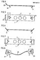
- FIGS. 4 and 5 The two types of variants represented in FIGS. 4 and 5 then 6 and 7 are with a simple triangular hooking point 16 and 17 that can be folded around their base 18 and 19 at a short distance from the end (FIGS. 4 and 5), or foldable around a transverse line 20 and 21 passing through their base ( Figures 6 and 7) allowing easier folding of the ends thus achieving in a single point the equivalent of the latching tabs of the basic variant.
- FIGS. 4 and 5 also has at one of its ends a gripping tab 22 which can be tilted around a transverse line 23.
- the fasteners 3 and 4 are plates 24 and 25 joined by a simple or multifilar elastic link 26.
Abstract
Description
La présente invention se rapporte à une attache linéaire du type agrafe pour la réunion des bords d'un revêtement de protection ou d'isolation thermique à utiliser plus particulièrement dans les appareils de chauffage, notamment les chaudières.The present invention relates to a linear fastener of the clip type for joining the edges of a protective or thermal insulation coating to be used more particularly in heating appliances, in particular boilers.
L'isolation thermique des chaudières est réalisée par un revêtement de laine de verre ou de mousse synthétique présentant sur l'une de ses faces une finition assurant la propreté et l'esthétique.The thermal insulation of the boilers is carried out by a coating of glass wool or synthetic foam having on one of its faces a finish ensuring cleanliness and aesthetics.
Le corps de chauffe et les ballons d'eau chaude sanitaire associés sont entourés latéralement du revêtement isolant à la manière d'un manteau dont le maintien résulte de la jonction et la réunion de ses bords latéraux par un ruban adhésif.The heating body and the associated domestic hot water tanks are surrounded laterally by the insulating coating in the manner of a mantle, the retention of which results from the junction and the joining of its lateral edges by an adhesive tape.
Malheureusement, l'adhérence de ce ruban sur le revêtement de finition s'avère faible en raison des microfibres de verre qui le traversent et de la chaleur dégagée par la chaudière. Il en est de même pour tous les types de fermeture à effet adhésif.Unfortunately, the adhesion of this tape to the finish coating is poor due to the glass microfibers passing through it and the heat given off by the boiler. The same applies to all types of adhesive effect closure.
La présente invention a pour but de remédier à l'inconvénient de la précarité du maintien et d'apporter une facilité de pose tout à fait intéressante en même temps qu'un coût de revient modique.The object of the present invention is to remedy the drawback of the precariousness of the maintenance and to provide ease of installation which is quite advantageous at the same time as a low cost price.
A cet effet, l'invention se rapporte à une attache linéaire pour le maintien d'un revêtement isolant caractérisée en ce qu'elle est formée par une bande de tôle présentant des extrémités symétriques à pointes antirecul, une des extrémités au moins étant prolongée par une patte de préhension destinée à faciliter la pose de l'attache.To this end, the invention relates to a linear fastener for maintaining an insulating coating, characterized in that it is formed by a sheet metal strip having symmetrical ends with anti-kickback points, at least one of the ends being extended by a gripping tab intended to facilitate the fitting of the fastener.
Les principaux avantages de l'invention concernent son prix de revient très inférieur à celui du ruban adhésif et sa mise en place rapide et aisée.The main advantages of the invention relate to its cost price much lower than that of the adhesive tape and its rapid and easy installation.
En effet, elle peut être fabriquée en continu dans une bande de tôle par un outille; découpe., La conjonction de ces deux effets permet de réaliser des économies substantielles sur de grandes séries.Indeed, it can be manufactured continuously in a sheet metal strip by a tool; cutting., The combination of these two effects allows substantial savings to be made on large series.
Les caractéristiques de l'invention et d'autres avantages sont consignés dans la description qui suit effectuée à titre d'exemple non limitatif sur plusieurs variantes d'exécution en référence aux dessins accompagnants dans lesquels :
- . la figure 1 est une vue en perspective de la variante de base de l'agrafe selon l'invention en configuration droite ;
- . la figure 2 est une vue en perspective de la variante de base de l'invention en configuration coudée ;
- . la figure 3 est une vue à plat de l'agrafe en bande telle que sortant de l'outil de découpe ;
- . les figures 4 et 5 sont des vues de profil et en plan d'une autre variante ;
- . les figures 6 et 7 sont des vues de profil et en plan d'une variante supplémentaire ;
- . la figure 8 est une vue en plan d'une variante à lien élastique ;
- . la figure 9 est une vue schématique en perspective de deux exemples d'utilisation.
- . Figure 1 is a perspective view of the basic variant of the clip according to the invention in straight configuration;
- . Figure 2 is a perspective view of the basic variant of the invention in a bent configuration;
- . Figure 3 is a flat view of the strip clip as exiting the cutting tool;
- . Figures 4 and 5 are side and plan views of another variant;
- . Figures 6 and 7 are side and plan views of an additional variant;
- . Figure 8 is a plan view of a variant with elastic link;
- . Figure 9 is a schematic perspective view of two examples of use.
L'attache en forme d'agrafe selon l'invention est destinée principalement à réunir et à maintenir les deux bords d'un revêtement enveloppant, par exemple une isolation de chaudière ou de ballon d'eau chaude, mais on peut envisager beaucoup d'autres applications telles par exemple le maintien de tissus ou de toile de protection ou d'esthétique sur un support mou ou tout autre application analogue.The clip-shaped fastener according to the invention is intended mainly to join and maintain the two edges of an enveloping coating, for example a boiler or hot water tank insulation, but one can consider a lot of other applications such as the maintenance of fabrics or protective or aesthetic canvas on a soft support or any other similar application.
Par ailleurs, sa fabrication par découpage à la presse dans une bande de tôle continue présente un avantage considérable au niveau de son prix de revient ou de son conditionnement. En effet, il suffit d'individualiser les agrafes par fractionnement le long des lignes de prédécoupe pour les trouver directement prêtes à l'emploi.Furthermore, its manufacture by cutting with a press from a continuous sheet strip has a considerable advantage in terms of its cost price or its packaging. Indeed, it suffices to individualize the staples by splitting along the precut lines to find them directly ready for use.
L'attache selon l'invention se présente sous la forme générale d'une agrafe à corps plat 1 de forme générale rectangulaire, pourvu en partie centrale d'une ou de plusieurs ouverture(s), par exemple circulaire(s), telle(s) que 2 destinée(s) à faciliter le pliage nécessaire pour une utilisation en configuration coudée représentée sur les figures 2 et 9.The fastener according to the invention is in the general form of a staple with a
En raison de sa forme, on emploiera ci-après indifféremment les termes d'attache ou d'agrafe pour désigner l'invention.Because of its shape, the terms of attachment or staple will be used interchangeably hereinafter to designate the invention.
Les extrémités du corps 1 sont conformées en pattes d'accrochage pliables 3 et 4 dont la forme générale peut varier légèrement.The ends of the
A titre illustratif, deux exemples de variantes possibles sont représentés en figures de 4 à 7.By way of illustration, two examples of possible variants are shown in figures from 4 to 7.
Dans le mode d'exécution de base, les pattes d'accrochage 3 et 4 sont formées par les extrémités de l'agrafe et délimitées par deux découpes symétriques convergentes 5 et 6 pratiquées à une distance de l'extrémité de l'ordre de la largeur de l'agrafe.In the basic embodiment, the
Les découpes sont ouvertes du côté des bords longitudinaux de l'attache et se terminent de l'autre côté par une extrémité en arrondi pour éviter l'effet de cisaillage du revêtement.The cutouts are open on the side of the longitudinal edges of the fastener and end on the other side with a rounded end to avoid the shearing effect of the coating.
Ces découpes délimitent sur chaque patte d'accrochage deux pointes divergentes symétriques antirecul 7 et 8.These cutouts delimit on each hooking lug two divergent symmetrical
La plus faible largeur du corps 1 au niveau de l'espace 9 situé entre les pointes 7 et 8 permet le pliage de chaque extrémité par simple levage comme le montrent les figures 2 et 3.The narrower width of the
La figure 9 montre un exemple d'utilisation pour la réunion des deux bords verticaux d'extrémité 10 et 11 d'un revêtement thermiquement isolant de surface latérale 12 en configuration coudée et la réunion des bords horizontaux 13 et 14 entre un panneau 15 de couverture supérieur en configuration coudée.FIG. 9 shows an example of use for joining the two
On remarque l'utilisation particulièrement simple et la pose tout à fait aisée.We note the particularly simple use and the installation quite easy.
Par ailleurs, la longueur des pointes 7 et 8 garantit une bonne efficacité d'accrochage et l'arrondi d'extrémité des découpes 5 et 6 évite le cisaillage du revêtement.Furthermore, the length of the
Les deux types de variantes représentées en figure 4 et 5 puis 6 et 7 sont à simple pointe d'accrochage triangulaire 16 et 17 pliable autour de leur base 18 et 19 à une faible distance de l'extrémité (figures 4 et 5), ou pliable autour d'une ligne transversale 20 et 21 passant par leur base (figures 6 et 7) permettant un pliage plus facile des extrémités réalisant ainsi en une seule pointe l'équivalent des pattes d'accrochage de la variante de base.The two types of variants represented in FIGS. 4 and 5 then 6 and 7 are with a simple
La variante représentée en figures 4 et 5 présente en plus à l'une de ses extrémités une patte de préhension 22 inclinable autour d'une ligne transversale 23.The variant shown in FIGS. 4 and 5 also has at one of its ends a
Une dernière variante imaginée par les inventeurs (figure 8) présente une liaison souple élastique entre les deux pattes d'accrochage.A last variant imagined by the inventors (Figure 8) has a flexible elastic connection between the two lugs.
Dans cette variante, les attaches 3 et 4 sont des plaquettes 24 et 25 réunies par un lien élastique 26 simple ou multifilaire.In this variant, the
Dans ces plaquettes, sont découpées des pointes d'accrochage uniques ou doubles comme précédemment.In these plates, are cut single or double attachment points as before.
On a décrit ci-dessus trois variantes à titre d'exemple, il est bien entendu toutefois que diverses autres variantes découlant de celles décrites ou des modifications secondaires et changements sans apport inventif entrent parfaitement dans le cadre de la présente invention.Three variants have been described above by way of example, it is understood, however, that various other variants resulting from those described or secondary modifications and changes without any inventive contribution fall perfectly within the scope of the present invention.
Claims (10)
Applications Claiming Priority (2)
| Application Number | Priority Date | Filing Date | Title |
|---|---|---|---|
| FR8510849 | 1985-07-12 | ||
| FR8510849A FR2584784B1 (en) | 1985-07-12 | 1985-07-12 | CLIP-SHAPED FASTENER FOR JOINING THE TWO EDGES OF AN ENVELOPING COVERING |
Publications (2)
| Publication Number | Publication Date |
|---|---|
| EP0214917A1 true EP0214917A1 (en) | 1987-03-18 |
| EP0214917B1 EP0214917B1 (en) | 1990-11-14 |
Family
ID=9321326
Family Applications (1)
| Application Number | Title | Priority Date | Filing Date |
|---|---|---|---|
| EP19860440054 Expired - Lifetime EP0214917B1 (en) | 1985-07-12 | 1986-07-02 | Fastener in staple form to join two edges of enveloping clothing |
Country Status (3)
| Country | Link |
|---|---|
| EP (1) | EP0214917B1 (en) |
| DE (1) | DE3675614D1 (en) |
| FR (1) | FR2584784B1 (en) |
Cited By (2)
| Publication number | Priority date | Publication date | Assignee | Title |
|---|---|---|---|---|
| FR2737756A1 (en) * | 1995-08-09 | 1997-02-14 | Sogal France | Connecting clip for joining wooden furniture panels - comprises L=shaped pentagonal metal sheet whose two planes are parallel to the part walls, each plane having pointed ends for fixing to parts |
| GB2415474A (en) * | 2004-03-16 | 2005-12-28 | Keith William Bendon | Securement device |
Citations (4)
| Publication number | Priority date | Publication date | Assignee | Title |
|---|---|---|---|---|
| US1921999A (en) * | 1932-11-11 | 1933-08-08 | Fairleigh S Dickinson | Bandage fastener |
| FR1336740A (en) * | 1962-07-06 | 1963-09-06 | Johann Schwab | Retaining clip for dressing bands |
| GB1113656A (en) * | 1965-09-02 | 1968-05-15 | United Carr Inc | Fastener device |
| FR2383587A7 (en) * | 1977-03-11 | 1978-10-06 | Viessmann Hans | Thermal insulation jacket for central heating boiler - has end panels supported by metal frames and cut to accommodate pipes, with slots closed by clamps to block air gaps |
-
1985
- 1985-07-12 FR FR8510849A patent/FR2584784B1/en not_active Expired
-
1986
- 1986-07-02 DE DE8686440054T patent/DE3675614D1/en not_active Expired - Fee Related
- 1986-07-02 EP EP19860440054 patent/EP0214917B1/en not_active Expired - Lifetime
Patent Citations (4)
| Publication number | Priority date | Publication date | Assignee | Title |
|---|---|---|---|---|
| US1921999A (en) * | 1932-11-11 | 1933-08-08 | Fairleigh S Dickinson | Bandage fastener |
| FR1336740A (en) * | 1962-07-06 | 1963-09-06 | Johann Schwab | Retaining clip for dressing bands |
| GB1113656A (en) * | 1965-09-02 | 1968-05-15 | United Carr Inc | Fastener device |
| FR2383587A7 (en) * | 1977-03-11 | 1978-10-06 | Viessmann Hans | Thermal insulation jacket for central heating boiler - has end panels supported by metal frames and cut to accommodate pipes, with slots closed by clamps to block air gaps |
Cited By (3)
| Publication number | Priority date | Publication date | Assignee | Title |
|---|---|---|---|---|
| FR2737756A1 (en) * | 1995-08-09 | 1997-02-14 | Sogal France | Connecting clip for joining wooden furniture panels - comprises L=shaped pentagonal metal sheet whose two planes are parallel to the part walls, each plane having pointed ends for fixing to parts |
| GB2415474A (en) * | 2004-03-16 | 2005-12-28 | Keith William Bendon | Securement device |
| GB2415474B (en) * | 2004-03-16 | 2007-05-23 | Keith William Bendon | Improvements in and relating to securement devices & apparatus |
Also Published As
| Publication number | Publication date |
|---|---|
| DE3675614D1 (en) | 1990-12-20 |
| FR2584784B1 (en) | 1988-08-05 |
| FR2584784A1 (en) | 1987-01-16 |
| EP0214917B1 (en) | 1990-11-14 |
Similar Documents
| Publication | Publication Date | Title |
|---|---|---|
| EP0410822B1 (en) | Metallic roof covering and supports for such covering | |
| EP0214917A1 (en) | Fastener in staple form to join two edges of enveloping clothing | |
| EP0237443B1 (en) | Heat exchanger for a gas-fired water heater | |
| FR2661207A1 (en) | Device for fixing coverings of various types on walls and roof spaces | |
| EP1042571B1 (en) | Threshold bar with level compensation | |
| EP0546971B1 (en) | Invisible junction device, suitable in particular for tight fabrics | |
| EP0371532B1 (en) | Radiator for a central-heating system | |
| EP0399874A1 (en) | Batten assembly, particularly for covering of pitched roofs | |
| FR2766905A1 (en) | Folded section girder for building construction | |
| BE1006537A3 (en) | System for fixing insulation products. | |
| FR2562205A1 (en) | Lagging jacket for hot water tank | |
| EP0767283A1 (en) | Watertight roof covering | |
| BE1000052A7 (en) | Plate roof insulation. | |
| EP0530101A1 (en) | Watertight roof for buildings and method of laying the same | |
| FR2588425A1 (en) | Skirting board having an upper compartment | |
| FR2516964A1 (en) | Stud and clamps for assembling roof top solar energy panels - pref. involving seals and spacers of silicone rubber to tolerate differential expansion | |
| EP0539284A1 (en) | Mounting clamp for a drain pipe | |
| CH629369A5 (en) | Multi-level electric oven | |
| FR3017633A1 (en) | DEVICE FOR DESCENTING AND DRAINING RAINWATER WATER OUT OF A ROOF GUTTER OF A CONSTRUCTION | |
| FR2515323A1 (en) | Hot air recuperator for building - has vented trunking on roof rafters ducted to distribution circuit | |
| FR3052372B1 (en) | SUCTION BELL | |
| FR2685717A1 (en) | Improved fastening joint for edges of urban panels | |
| FR2591306A1 (en) | Method for producing a fixed fluid-transport network in a building, guiding and holding device for producing such a network, and network produced by this method | |
| FR2524518A3 (en) | JOINT FOR OUTDOOR PANELS | |
| FR2537633A1 (en) | Element for fixing a roofing made from sheets |
Legal Events
| Date | Code | Title | Description |
|---|---|---|---|
| PUAI | Public reference made under article 153(3) epc to a published international application that has entered the european phase |
Free format text: ORIGINAL CODE: 0009012 |
|
| AK | Designated contracting states |
Kind code of ref document: A1 Designated state(s): BE CH DE GB IT LI NL |
|
| 17P | Request for examination filed |
Effective date: 19870211 |
|
| 17Q | First examination report despatched |
Effective date: 19880519 |
|
| GRAA | (expected) grant |
Free format text: ORIGINAL CODE: 0009210 |
|
| AK | Designated contracting states |
Kind code of ref document: B1 Designated state(s): BE CH DE GB IT LI NL |
|
| PG25 | Lapsed in a contracting state [announced via postgrant information from national office to epo] |
Ref country code: NL Effective date: 19901114 |
|
| REF | Corresponds to: |
Ref document number: 3675614 Country of ref document: DE Date of ref document: 19901220 |
|
| GBT | Gb: translation of ep patent filed (gb section 77(6)(a)/1977) | ||
| ITF | It: translation for a ep patent filed |
Owner name: ST. ASSOC. MARIETTI & PIPPARELLI |
|
| NLV1 | Nl: lapsed or annulled due to failure to fulfill the requirements of art. 29p and 29m of the patents act | ||
| PG25 | Lapsed in a contracting state [announced via postgrant information from national office to epo] |
Ref country code: GB Effective date: 19910702 |
|
| PG25 | Lapsed in a contracting state [announced via postgrant information from national office to epo] |
Ref country code: LI Effective date: 19910731 Ref country code: CH Effective date: 19910731 Ref country code: BE Effective date: 19910731 |
|
| PLBE | No opposition filed within time limit |
Free format text: ORIGINAL CODE: 0009261 |
|
| STAA | Information on the status of an ep patent application or granted ep patent |
Free format text: STATUS: NO OPPOSITION FILED WITHIN TIME LIMIT |
|
| RAP2 | Party data changed (patent owner data changed or rights of a patent transferred) |
Owner name: DE DIETRICH THERMIQUE, SOCIETE ANONYME |
|
| 26N | No opposition filed | ||
| BERE | Be: lapsed |
Owner name: DE DIETRICH THERMIQUE Effective date: 19910731 |
|
| GBPC | Gb: european patent ceased through non-payment of renewal fee | ||
| REG | Reference to a national code |
Ref country code: CH Ref legal event code: PL |
|
| PGFP | Annual fee paid to national office [announced via postgrant information from national office to epo] |
Ref country code: DE Payment date: 19940802 Year of fee payment: 9 |
|
| PG25 | Lapsed in a contracting state [announced via postgrant information from national office to epo] |
Ref country code: DE Effective date: 19960402 |
|
| PG25 | Lapsed in a contracting state [announced via postgrant information from national office to epo] |
Ref country code: IT Free format text: LAPSE BECAUSE OF NON-PAYMENT OF DUE FEES;WARNING: LAPSES OF ITALIAN PATENTS WITH EFFECTIVE DATE BEFORE 2007 MAY HAVE OCCURRED AT ANY TIME BEFORE 2007. THE CORRECT EFFECTIVE DATE MAY BE DIFFERENT FROM THE ONE RECORDED. Effective date: 20050702 |