EP0767283A1 - Watertight roof covering - Google Patents
Watertight roof covering Download PDFInfo
- Publication number
- EP0767283A1 EP0767283A1 EP96402069A EP96402069A EP0767283A1 EP 0767283 A1 EP0767283 A1 EP 0767283A1 EP 96402069 A EP96402069 A EP 96402069A EP 96402069 A EP96402069 A EP 96402069A EP 0767283 A1 EP0767283 A1 EP 0767283A1
- Authority
- EP
- European Patent Office
- Prior art keywords
- profile
- support element
- rib
- cover according
- added
- Prior art date
- Legal status (The legal status is an assumption and is not a legal conclusion. Google has not performed a legal analysis and makes no representation as to the accuracy of the status listed.)
- Withdrawn
Links
- 239000011248 coating agent Substances 0.000 claims description 4
- 238000000576 coating method Methods 0.000 claims description 4
- 125000006850 spacer group Chemical group 0.000 claims description 2
- 238000004078 waterproofing Methods 0.000 claims 1
- 239000000463 material Substances 0.000 abstract description 3
- 210000002105 tongue Anatomy 0.000 abstract 1
- 239000002184 metal Substances 0.000 description 3
- 238000009413 insulation Methods 0.000 description 2
- 239000011490 mineral wool Substances 0.000 description 2
- 210000002268 wool Anatomy 0.000 description 2
- 241000826860 Trapezium Species 0.000 description 1
- 230000015556 catabolic process Effects 0.000 description 1
- 239000011521 glass Substances 0.000 description 1
- 229910052500 inorganic mineral Inorganic materials 0.000 description 1
- 239000011707 mineral Substances 0.000 description 1
- 230000000284 resting effect Effects 0.000 description 1
- 238000007789 sealing Methods 0.000 description 1
Images


Classifications
-
- E—FIXED CONSTRUCTIONS
- E04—BUILDING
- E04D—ROOF COVERINGS; SKY-LIGHTS; GUTTERS; ROOF-WORKING TOOLS
- E04D13/00—Special arrangements or devices in connection with roof coverings; Protection against birds; Roof drainage ; Sky-lights
- E04D13/16—Insulating devices or arrangements in so far as the roof covering is concerned, e.g. characterised by the material or composition of the roof insulating material or its integration in the roof structure
- E04D13/1606—Insulation of the roof covering characterised by its integration in the roof structure
- E04D13/1643—Insulation of the roof covering characterised by its integration in the roof structure the roof structure being formed by load bearing corrugated sheets, e.g. profiled sheet metal roofs
-
- E—FIXED CONSTRUCTIONS
- E04—BUILDING
- E04D—ROOF COVERINGS; SKY-LIGHTS; GUTTERS; ROOF-WORKING TOOLS
- E04D3/00—Roof covering by making use of flat or curved slabs or stiff sheets
- E04D3/36—Connecting; Fastening
- E04D3/3601—Connecting; Fastening of roof covering supported by the roof structure with interposition of a insulating layer
- E04D3/3603—Connecting; Fastening of roof covering supported by the roof structure with interposition of a insulating layer the fastening means being screws or nails
-
- E—FIXED CONSTRUCTIONS
- E04—BUILDING
- E04D—ROOF COVERINGS; SKY-LIGHTS; GUTTERS; ROOF-WORKING TOOLS
- E04D3/00—Roof covering by making use of flat or curved slabs or stiff sheets
- E04D3/36—Connecting; Fastening
- E04D3/3607—Connecting; Fastening the fastening means comprising spacer means adapted to the shape of the profiled roof covering
Definitions
- the present invention relates to a waterproof roof covering comprising a support element, generally a profiled sheet, an insulating mat and at least one waterproof covering, the whole being fixed to structural elements of the roof, such as breakdowns.
- the invention provides a waterproof roof covering using standard profiled support elements comprising ribs on which at least one insulation mat is mechanically fixed, the fastenings being carried out on a profile attached to at least one of the ribs and of dimensions and shape adapted to the dimensions and shape of the rib and forming with them a space intended in particular to make the mechanical fixing means not visible under the roof, the added profile itself being fixed on the profiled support elements.
- the attached profile used according to the invention has a structure adapted to the structure of the rib and, preferably, a structure allowing mounting by at least partial interlocking in the rib of the profiled support, the face on which the fixing takes place. disposed in the attached position at a level substantially equal to the upper level of the ribs.
- the added profile has, where appropriate, an elasticity allowing in particular an interlocking that is at least partial.
- the added profile is a substantially planar profile bearing on parts of the upper edges of the rib.
- this profile may have one or more longitudinal ribs, that is to say parallel to the rib of the profiled support.
- This planar profile can also have a structure facilitating its centering and its positioning in the rib of the profiled support. It is thus possible to provide punctures folded over the sides of the rib or at least one folding which can match this side of the rib.
- the attached profile can be fixed to the edges of the rib of the profiled support by screws of small dimensions which are almost invisible.
- the added profile has a structure allowing a total or almost total fitting in a rib of the support element by forming a closed space.
- the added profile can then have the shape of an inverted U, the two wings of the U, advantageously made of thin sheet metal, coming if necessary to bear on the inclined sides of the rib, adapting by virtue of the elasticity of the wings. at this inclination of the sides of the rib.
- the profile fixing system attached to the support element can then use the same fixing system as the support element in the structure of the roof.
- the added profile can be formed of two elements joining together to form a closed space in a rib of the support element.
- the waterproof cover 1 is a cover for the roof of a room, based on purlins 2.
- the cover 1 comprises a support element 3 formed from contiguous profiled sheets 4 which may have small ribs longitudinal 5 to improve their rigidity.
- the support element 3 has ribs 6 whose base 7 is supported and fixed by mechanical means 8 on the purlins 2. On the support element 3 are arranged panels 9 thermal and / or acoustic insulation, in particular wool mineral.
- the insulating panel 9 can advantageously include a bonding coating 10 in particular based on a bituminous material. On this panel 9 is finally arranged and bonded at least one layer 11 of a waterproof coating which can also be based on a bituminous material.
- the insulating panels are mechanically fixed, for example using plates 12 and screws 13 or studs in added profiles 14 made of sheet metal, for example, which cover at least one of the ribs 6 of the support element.
- the ribs 6 covered by the added profiles are regularly spaced. Generally, at least one rib 6 is covered by an attached profile for each profiled sheet.
- the attached profile 14 made of sheet metal 1 mm thick bears on the upper edges 15 of the rib and advantageously has two longitudinal folds 16 which facilitate good centering of the profile added on the rib.
- the added profile 14 may also have a central fold 17 improving the rigidity of the profile.
- the added profile 14 can be fixed to the support element 3 by screws 18 of small dimensions which are almost invisible under the roof.
- the insulating panel 9 is fixed to the added profile using plates 12 and screws 13 which pass through this profile. The end of the screws is then located in the closed space 19 created by the association of the profile and the rib, and is not visible under the roof.
- the number of plates 12 and screws 13 may vary from one cover to another depending in particular on the type of panel used, the geographic location of the cover, etc. It is understood that the screws for fixing the panels will be arranged according to lines that correspond to the arrangement of the profiles reported.
- FIG. 3 shows a variant of an attached profile 20 according to the invention.
- the added profile 20 is fully fitted into a rib 6 of the support element 3.
- the profile 20 has a substantially trapezoidal shape 21, the large base 22 serving for fixing in particular by plates 12 and screws 13 of the insulating panels 9.
- the attachment of the added profile 20 to the support element 3 can be carried out by the same means as those used for the attachment of the support element to the purlin. These are for example screws 8 which here are provided with spacers 23 and washers 24 forming a housing 26 and allowing mounting by “clipping”, that is to say by pinching and / or imprisonment of the two curved wings 25 forming the small base of the trapezoid.
- the two sides 27 of the trapezium are substantially parallel and, where appropriate, in contact with the sides 28 of the rib.
- the establishment of the added profile is facilitated by an elasticity of the sides and of the wings thereof which can engage under the washer 24 during the establishment of the profile by simple push from top to bottom.
- FIG. 4 shows a third variant of an attached profile used in accordance with the invention.
- the profile 29 is formed of two parts 30, 31 which can be mounted one on the other by pinching and together forming a shape with a trapezoidal section.
- a base part 30 is fixed to the support element 3 using the means 8 used for fixing the support element 3 to the purlin 2.
- This base part 30 has the shape of a U whose base of the branches is inclined to follow the slope of the sides 28 of the rib 6.
- the upper end 32 of the U is bent outward so as to fix the top piece 31 which to this end also has ends 33 of curved arms.
- the insulating panel is fixed by means of plates 12 and screws 13 to the upper base 34 of the top piece 31.
- the ends 35 of the fixing screws are arranged in the closed space 19 formed here by the attached profile.
- FIG. 5 shows a fourth variant of an attached profile according to the invention.
- the added profile 36 is fully fitted into a rib 6 of the support element.
- the profile 36 has a substantially trapezoidal shape 37, the small base formed by two wings 38 resting on the support element 3, the large base 39 is fixed to the support element 3 by the same screws which fix the element on failure 2.
- the insulating panel is fixed to the added profile 36 by plates 12 and screws 13, the ends of which open into the interior space 19 and are therefore not visible under the roof.
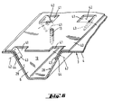
- FIG. 6 another variant of an attached profile 40 according to the invention is shown, which in combination with a rib 6 forms a space 19 intended to make the ends of the fixing screws not visible, on the underside of the cover. 13 insulating panels (not shown).
- the substantially flat attached profile 40 has punctures 41 arranged in two longitudinal lines, parallel to the upper edges of the rib, separated by the distance corresponding to the upper opening of said rib, so as to allow the centering of the profile attached to said rib and on the other hand its fixing by screws 42, the folded parts or tabs 43 of the punctures coming to bear on the upper ends 44 of the inclined blanks 28 of the rib.
- Small longitudinal ribs (not shown) can be provided in order to improve the rigidity of the added profile 40.
- the cover according to the invention can use, as insulating panel, any type of panel known in this type of application and in particular panels made of mineral wool, for example rock wool or wool of glass. These panels can be bare panels or advantageously panels provided with at least one waterproof coating, for example based on a bituminous product, capable of receiving known covering sealing systems and in particular systems based on bituminous products. or others.
Landscapes
- Engineering & Computer Science (AREA)
- Architecture (AREA)
- Civil Engineering (AREA)
- Structural Engineering (AREA)
- Mechanical Engineering (AREA)
- Roof Covering Using Slabs Or Stiff Sheets (AREA)
Abstract
Description
La présente invention est relative à une couverture étanche pour toiture comprenant un élément de support, généralement une tôle profilée, un matelas isolant et au moins un revêtement d'étanchéité, l'ensemble étant fixé à des éléments de structure de la toiture, tels que des pannes.The present invention relates to a waterproof roof covering comprising a support element, generally a profiled sheet, an insulating mat and at least one waterproof covering, the whole being fixed to structural elements of the roof, such as breakdowns.
Pour résister aux efforts en compression ou en arrachement notamment en cas de violentes tempêtes, il est d'usage de fixer mécaniquement au moins le matelas isolant à la tôle profilée. Cette fixation mécanique à l'aide de vis par exemple traverse la tôle profilée et est visible en sous-face de la couverture, ce qui n'est pas satisfaisant.To resist compressive or tearing forces, particularly in the event of severe storms, it is customary to mechanically fix at least the insulating mat to the profiled sheet. This mechanical fixing using screws for example passes through the profiled sheet and is visible on the underside of the cover, which is not satisfactory.
Pour rendre ces fixations non invisible, on a déjà proposé par exemple dans la publication de brevet EP 0 553 012 d'utiliser, en tant qu'élément de support, des tôles contiguës comportant des bords se superposant mutuellement de l'une à l'autre dans une zone de recouvrement marginale formant un logement fermé dans lequel s'étend l'extrémité des moyens de fixation.To make these fasteners non-invisible, it has already been proposed for example in patent publication EP 0 553 012 to use, as a support element, contiguous sheets having edges overlapping each other from one to the another in a marginal overlap zone forming a closed housing in which extends the end of the fixing means.
Cette solution nécessite néanmoins l'utilisation de tôles profilées spécifiques.This solution nevertheless requires the use of specific profiled sheets.
L'invention propose une couverture étanche pour toiture utilisant des éléments de supports profilés standard comportant des nervures sur lesquels sont fixés mécaniquement au moins un matelas d'isolation, les fixations s'effectuant sur un profil rapporté sur au moins une des nervures et de dimensions et forme adaptées aux dimensions et forme de la nervure et formant avec elles un espace destiné notamment à rendre non visibles en sous-toiture les moyens mécaniques de fixation, le profil rapporté étant lui-même fixé sur les éléments de support profilés.The invention provides a waterproof roof covering using standard profiled support elements comprising ribs on which at least one insulation mat is mechanically fixed, the fastenings being carried out on a profile attached to at least one of the ribs and of dimensions and shape adapted to the dimensions and shape of the rib and forming with them a space intended in particular to make the mechanical fixing means not visible under the roof, the added profile itself being fixed on the profiled support elements.
Le profil rapporté utilisé selon l'invention présente une structure adaptée à la structure de la nervure et, de préférence, une structure permettant un montage par emboîtement au moins partiel dans la nervure du support profilé, la face sur laquelle s'effectue la fixation étant disposée en position rapportée à un niveau sensiblement égal au niveau supérieur des nervures. Le profil rapporté présente le cas échéant une élasticité permettant notamment un emboitement au moins partiel.The attached profile used according to the invention has a structure adapted to the structure of the rib and, preferably, a structure allowing mounting by at least partial interlocking in the rib of the profiled support, the face on which the fixing takes place. disposed in the attached position at a level substantially equal to the upper level of the ribs. The added profile has, where appropriate, an elasticity allowing in particular an interlocking that is at least partial.
Selon une première forme de réalisation de l'invention, le profil rapporté est un profil sensiblement plan prenant appui sur des parties des bords supérieures de la nervure. Afin d'augmenter sa rigidité, ce profil peut présenter une ou plusieurs nervures longitudinales, c'est-à-dire parallèles à la nervure du support profilé. Ce profil plan peut aussi présenter une structure facilitant son centrage et sa mise en place dans la nervure du support profilé. On peut ainsi prévoir des crevés rabattus sur les flancs de la nervure ou encore au moins un pliage pouvant épouser ce flanc de la nervure. Le profil rapporté peut être fixé sur les bords de la nervure du support profilé par des vis de petites dimensions quasi invisibles.According to a first embodiment of the invention, the added profile is a substantially planar profile bearing on parts of the upper edges of the rib. In order to increase its rigidity, this profile may have one or more longitudinal ribs, that is to say parallel to the rib of the profiled support. This planar profile can also have a structure facilitating its centering and its positioning in the rib of the profiled support. It is thus possible to provide punctures folded over the sides of the rib or at least one folding which can match this side of the rib. The attached profile can be fixed to the edges of the rib of the profiled support by screws of small dimensions which are almost invisible.
Selon une autre forme de réalisation de l'invention, le profil rapporté présente une structure permettant un emboîtement total ou quasi total dans une nervure de l'élément de support en formant un espace fermé. Le profil rapporté peut alors présenter la forme d'un U inversé, les deux ailes du U, avantageusement en tôle mince, venant le cas échéant s'appuyer sur les flancs inclinés de la nervure en s'adaptant grâce à l'élasticité des ailes à cette inclinaison des flancs de la nervure. Le système de fixation du profil rapporté sur l'élément support peut alors utiliser le même système de fixation que l'élément support dans la structure de la toiture.According to another embodiment of the invention, the added profile has a structure allowing a total or almost total fitting in a rib of the support element by forming a closed space. The added profile can then have the shape of an inverted U, the two wings of the U, advantageously made of thin sheet metal, coming if necessary to bear on the inclined sides of the rib, adapting by virtue of the elasticity of the wings. at this inclination of the sides of the rib. The profile fixing system attached to the support element can then use the same fixing system as the support element in the structure of the roof.
Selon une autre forme de réalisation de l'invention, le profil rapporté peut être formé de deux élément s'assemblant pour former un espace fermé dans une nervure de l'élément de support.According to another embodiment of the invention, the added profile can be formed of two elements joining together to form a closed space in a rib of the support element.
D'autre avantages et caractéristiques de l'invention apparaîtront dans la description suivante d'exemples de réalisation de couverture étanche pour toiture faits en référence aux figures.
- La figure 1 représente une couverture selon l'invention utilisant une première variante d'un profil rapporté,
- La figure 2 représente une vue en section d'un détail de la figure 1 en particulier du profil rapporté,
- La figure 3 représente en section une deuxième variante d'un profil rapporté,
- La figure 4 représente en section une troisième variante d'un profil rapporté,
- La figure 5 représente en section une quatrième variante de profil rapporté.
- La figure 6 représente une cinquième variante d'un profil rapporté.
- FIG. 1 represents a cover according to the invention using a first variant of an attached profile,
- FIG. 2 represents a section view of a detail of FIG. 1 in particular of the attached profile,
- FIG. 3 shows in section a second variant of an attached profile,
- FIG. 4 shows in section a third variant of an attached profile,
- FIG. 5 shows in section a fourth variant of the added profile.
- FIG. 6 represents a fifth variant of an attached profile.
Sur la figure 1, la couverture étanche 1 selon l'invention est une couverture pour toiture d'un local, reposant sur des pannes 2. La couverture 1 comprend un élément de support 3 formé de tôles profilées 4 contiguës qui peuvent présenter des petites nervures longitudinales 5 en vue d'améliorer leur rigidité.In FIG. 1 , the
L'élément de support 3 présente des nervures 6 dont la base 7 est en appui et fixée par des moyens mécaniques 8 sur les pannes 2. Sur l'élément de support 3 sont disposés des panneaux 9 isolants thermiques et/ou acoustiques notamment en laine minérale.The
Le panneau isolant 9 peut avantageusement comporter un revêtement de liaison 10 notamment à base d'un matériau bitumineux. Sur ce panneau 9 est enfin disposée et liée au moins une couche 11 d'un revêtement étanche qui peut également être à base d'un matériau bitumineux.The
Les panneaux isolants sont fixés mécaniquement par exemple à l'aide de plaquettes 12 et de vis 13 ou de goujons dans des profils rapportés 14 en tôle par exemple, qui recouvrent au moins une des nervures 6 de l'élément support. Les nervures 6 recouvertes par les profils rapportés sont espacées régulièrement. Généralement, au moins une nervure 6 est recouverte par un profil rapporté pour chaque tôle profilée.The insulating panels are mechanically fixed, for
Sur la figure 2, le profil rapporté 14 en tôle de 1 mm d'épaisseur par exemple prend appui sur les bords supérieurs 15 de la nervure et présente avantageusement deux plis longitudinaux 16 qui facilitent un bon centrage du profil rapporté sur la nervure. Le profil rapporté 14 peut aussi présenter un pli central 17 améliorant la rigidité du profil. Le profil rapporté 14 peut être fixé à l'élément de support 3 par des vis 18 de petites dimensions quasi invisibles en sous-toiture. Comme représenté sur la figure, le panneau isolant 9 est fixé sur le profil rapporté à l'aide de plaquettes 12 et de vis 13 qui traversent ce profil. L'extrémité des vis est alors située dans l'espace fermé 19 créé par l'association du profil et de la nervure, et est non visible en sous-toiture. Le nombre de plaquettes 12 et de vis 13 peut varier d'une couverture à l'autre selon notamment le type de panneau utilisé, la situation géographique de la couverture, etc... On comprend que les vis de fixation des panneaux seront disposés selon des lignes qui correspondent à la disposition des profils rapportés.In FIG. 2 , the attached
Sur la figure 3 on a représenté une variante d'un profil rapporté 20 selon l'invention. Dans cette variante, le profil rapporté 20 est entièrement emboîté dans une nervure 6 de l'élément support 3. Le profil 20 présente une forme sensiblement trapézoïdale 21, la grande base 22 servant à la fixation notamment par des plaquettes 12 et des vis 13 des panneaux isolants 9. La fixation du profil rapporté 20 sur l'élément support 3 peut être réalisée par les mêmes moyens que ceux utilisés pour la fixation de l'élément support sur la panne. Il s'agit par exemple de vis 8 qui ici sont munies d'entretoises 23 et rondelles 24 formant un logement 26 et permettant un montage par « clipsage » c'est-à-dire par pincement et/ou emprisonnement des deux ailes recourbées 25 formant la petite base du trapèze. Les deux côtés 27 du trapèze sont sensiblement parallèles et le cas échéant au contact des flancs 28 de la nervure. La mise en place du profil rapporté est facilité par une élasticité des côtés et des ailes de celui-ci qui peuvent s'engager sous la rondelle 24 lors de la mise en place du profil par simple poussée de haut en bas. FIG. 3 shows a variant of an attached
Sur la figure 4 est représentée une troisième variante d'un profil rapporté utilisé conformément à l'invention. Dans cette variante, le profil 29 est formé de deux pièces 30, 31 pouvant se monter l'une sur l'autre par pincement et formant ensemble une forme à section trapézoïdale. Une pièce de base 30 est fixée sur l'élément de support 3 à l'aide des moyens 8 utilisés pour la fixation de l'élément de support 3 sur la panne 2. Cette pièce de base 30 présente la forme d'un U dont la base des branches est inclinée pour épouser la pente des flancs 28 de la nervure 6. L'extrémité supérieure 32 du U est recourbée vers l'extérieur de manière à fixer la pièce de dessus 31 qui à cette fin présente également des extrémités 33 de bras recourbés. FIG. 4 shows a third variant of an attached profile used in accordance with the invention. In this variant, the
Le panneau isolant est fixé par l'intermédiaire de plaquettes 12 et de vis 13 sur la base supérieure 34 de la pièce de dessus 31.The insulating panel is fixed by means of
Les extrémités 35 des vis de fixation sont disposées dans l'espace fermé 19 constitué ici par le profil rapporté.The
Sur la figure 5 est représentée une quatrième variante d'un profil rapporté selon l'invention. Dans cette variante, le profil rapporté 36 est entièrement emboîté dans une nervure 6 de l'élément support. Le profil 36 présente une forme sensiblement trapézoïdale 37, la petite base formée de deux ailes 38 reposant sur l'élément support 3, la grande base 39 est fixée à l'élément de support 3 par les mêmes vis qui assurent la fixation de cet élément à la panne 2. Le panneau isolant est fixé sur le profil rapporté 36 par des plaquettes 12 et des vis 13 dont les extrémités débouchent dans l'espace intérieur 19 et sont donc non visibles en sous- toiture. FIG. 5 shows a fourth variant of an attached profile according to the invention. In this variant, the added
Sur la figure 6, est représentée une autre variante d'un profil rapporté 40 selon l'invention qui en combinaison avec une nervure 6 forme un espace 19 destiné à rendre non visibles, en sous face de la couverture, les extrémités des vis de fixation 13 des panneaux isolants (non représentés). Le profil rapporté 40 sensiblement plat, présente des crevés 41 disposés selon deux lignes longitudinales, parallèles aux bords supérieurs de la nervure, séparées de la distance correspondant à l'ouverture supérieure de ladite nervure, de manière à permettre d'une part un centrage du profil rapporté sur ladite nervure et d'autre part sa fixation par vis 42, les parties rabattues ou languettes 43 des crevés venant s'appuyer sur les extrémités supérieures 44 des flans inclinés 28 de la nervure.In FIG. 6, another variant of an attached
Des petites nervures longitudinales (non représentées) peuvent être prévues afin d'améliorer la rigidité du profil rapporté 40.Small longitudinal ribs (not shown) can be provided in order to improve the rigidity of the added
La couverture selon l'invention peut utiliser, en tant que panneau isolant, tout type de panneau connu dans ce type d'application et notamment des panneaux en laine minérale, par exemple en laine de roche ou en laine de verre. Ces panneaux peuvent être des panneaux nus ou avantageusement des panneaux munis d'au moins un revêtement étanche, par exemple à base d'un produit bitumineux, susceptible de recevoir des systèmes d'étanchéïté de recouvrement connus et notamment des systèmes à base de produits bitumineux ou autres.The cover according to the invention can use, as insulating panel, any type of panel known in this type of application and in particular panels made of mineral wool, for example rock wool or wool of glass. These panels can be bare panels or advantageously panels provided with at least one waterproof coating, for example based on a bituminous product, capable of receiving known covering sealing systems and in particular systems based on bituminous products. or others.
Claims (10)
Applications Claiming Priority (2)
| Application Number | Priority Date | Filing Date | Title |
|---|---|---|---|
| FR9511594 | 1995-10-03 | ||
| FR9511594 | 1995-10-03 |
Publications (1)
| Publication Number | Publication Date |
|---|---|
| EP0767283A1 true EP0767283A1 (en) | 1997-04-09 |
Family
ID=9483171
Family Applications (1)
| Application Number | Title | Priority Date | Filing Date |
|---|---|---|---|
| EP96402069A Withdrawn EP0767283A1 (en) | 1995-10-03 | 1996-09-27 | Watertight roof covering |
Country Status (3)
| Country | Link |
|---|---|
| EP (1) | EP0767283A1 (en) |
| CZ (1) | CZ289096A3 (en) |
| PL (1) | PL316366A1 (en) |
Cited By (4)
| Publication number | Priority date | Publication date | Assignee | Title |
|---|---|---|---|---|
| DE19943661A1 (en) * | 1999-09-13 | 2001-03-15 | Zahn Harald Gmbh | Fastening system for mounting insulation and sealing materials on flat roofs with trapezium-shaped sheet metal supports uses screw inserted through bearer plate into counter panel fitted over retaining components on supports |
| DE10164653A1 (en) * | 2001-11-19 | 2003-06-05 | Zahn Harald Gmbh | Butt joint between two sheet metal roof elements is formed by profiled walls of elements overlapping in joining area with grooves removed from one area of roof element |
| ITCR20090013A1 (en) * | 2009-04-29 | 2010-10-30 | Marco Pietro Borrini | SYSTEM FOR PREPARING FIXING POINTS FOR SUPPORT STRUCTURES OF PHOTOVOLTAIC MODULES ON PREFABRICATED COVERS WITH Y-RODS OR TEGOLI ALARI. |
| WO2012143035A1 (en) * | 2011-04-18 | 2012-10-26 | Fibrecem Holding Ag | Reinforcing plate |
Citations (11)
| Publication number | Priority date | Publication date | Assignee | Title |
|---|---|---|---|---|
| US2849756A (en) * | 1953-07-02 | 1958-09-02 | Airtherm Mfg Company | Insulation clip |
| US2910155A (en) * | 1956-05-07 | 1959-10-27 | Dominion Fasteners Ltd | Fasteners |
| US3284117A (en) * | 1964-06-23 | 1966-11-08 | Illinois Tool Works | Multi-piece clip |
| US3499673A (en) * | 1969-01-22 | 1970-03-10 | Illinois Tool Works | Roof decking clip |
| WO1981001436A1 (en) * | 1979-11-13 | 1981-05-28 | Encon Products Inc | Support spacer apparatus |
| EP0219402A1 (en) * | 1985-09-24 | 1987-04-22 | Haironville S.A. | Protection and insulation unit for buildings |
| FR2590610A1 (en) * | 1985-11-25 | 1987-05-29 | Smac Acieroid Sa | Composite roofing assembly based on metal elements in particular, forming a waterproof, flat and smooth covering |
| EP0297956A1 (en) * | 1987-06-25 | 1989-01-04 | L.R. Etanco | Fastening head with spacer used in the covering of various buildings |
| FR2671818A1 (en) * | 1991-01-22 | 1992-07-24 | Haironville Sa | Covering (roofing) assembly, especially cladding, for buildings |
| EP0553012A1 (en) * | 1992-01-24 | 1993-07-28 | Siplast S.A. | Watertight roof covering device |
| FR2718772A1 (en) * | 1994-04-14 | 1995-10-20 | Guetta Claude | Sealed and hidden fixing for construction cladding and cover |
-
1996
- 1996-09-27 EP EP96402069A patent/EP0767283A1/en not_active Withdrawn
- 1996-10-01 CZ CZ962890A patent/CZ289096A3/en unknown
- 1996-10-02 PL PL31636696A patent/PL316366A1/en unknown
Patent Citations (11)
| Publication number | Priority date | Publication date | Assignee | Title |
|---|---|---|---|---|
| US2849756A (en) * | 1953-07-02 | 1958-09-02 | Airtherm Mfg Company | Insulation clip |
| US2910155A (en) * | 1956-05-07 | 1959-10-27 | Dominion Fasteners Ltd | Fasteners |
| US3284117A (en) * | 1964-06-23 | 1966-11-08 | Illinois Tool Works | Multi-piece clip |
| US3499673A (en) * | 1969-01-22 | 1970-03-10 | Illinois Tool Works | Roof decking clip |
| WO1981001436A1 (en) * | 1979-11-13 | 1981-05-28 | Encon Products Inc | Support spacer apparatus |
| EP0219402A1 (en) * | 1985-09-24 | 1987-04-22 | Haironville S.A. | Protection and insulation unit for buildings |
| FR2590610A1 (en) * | 1985-11-25 | 1987-05-29 | Smac Acieroid Sa | Composite roofing assembly based on metal elements in particular, forming a waterproof, flat and smooth covering |
| EP0297956A1 (en) * | 1987-06-25 | 1989-01-04 | L.R. Etanco | Fastening head with spacer used in the covering of various buildings |
| FR2671818A1 (en) * | 1991-01-22 | 1992-07-24 | Haironville Sa | Covering (roofing) assembly, especially cladding, for buildings |
| EP0553012A1 (en) * | 1992-01-24 | 1993-07-28 | Siplast S.A. | Watertight roof covering device |
| FR2718772A1 (en) * | 1994-04-14 | 1995-10-20 | Guetta Claude | Sealed and hidden fixing for construction cladding and cover |
Cited By (6)
| Publication number | Priority date | Publication date | Assignee | Title |
|---|---|---|---|---|
| DE19943661A1 (en) * | 1999-09-13 | 2001-03-15 | Zahn Harald Gmbh | Fastening system for mounting insulation and sealing materials on flat roofs with trapezium-shaped sheet metal supports uses screw inserted through bearer plate into counter panel fitted over retaining components on supports |
| DE19943661B4 (en) * | 1999-09-13 | 2004-10-21 | Harald Zahn Gmbh | Fastening system for the application of insulation material and sealing sheets |
| DE10164653A1 (en) * | 2001-11-19 | 2003-06-05 | Zahn Harald Gmbh | Butt joint between two sheet metal roof elements is formed by profiled walls of elements overlapping in joining area with grooves removed from one area of roof element |
| DE10164653B4 (en) * | 2001-11-19 | 2004-01-29 | Harald Zahn Gmbh | Frontal butt joint between two sheet metal roof elements of a flat roof |
| ITCR20090013A1 (en) * | 2009-04-29 | 2010-10-30 | Marco Pietro Borrini | SYSTEM FOR PREPARING FIXING POINTS FOR SUPPORT STRUCTURES OF PHOTOVOLTAIC MODULES ON PREFABRICATED COVERS WITH Y-RODS OR TEGOLI ALARI. |
| WO2012143035A1 (en) * | 2011-04-18 | 2012-10-26 | Fibrecem Holding Ag | Reinforcing plate |
Also Published As
| Publication number | Publication date |
|---|---|
| CZ289096A3 (en) | 1997-04-16 |
| PL316366A1 (en) | 1997-04-14 |
Similar Documents
| Publication | Publication Date | Title |
|---|---|---|
| EP0119114B1 (en) | Device for creating double claddings or curtain walls, and supporting parts, supports and pincers for using this device | |
| EP0553012B1 (en) | Watertight roof covering device | |
| EP3303723A1 (en) | Panel, assembly of panels, and associated roof | |
| FR2957953A1 (en) | Device for supporting e.g. photovoltaic solar panel integrated in roof of dwelling, has membrane whose width is adapted in manner to extend above upper parts of sections to obtain overlapping zone at level of junction zone of elements | |
| EP2591508A2 (en) | Device for supporting and attaching panels or the like, and roof system comprising such a device | |
| EP3074578A1 (en) | Panel, panel assembly, and related roofing | |
| EP0767283A1 (en) | Watertight roof covering | |
| EP0557170B1 (en) | Insulating and impervious roof for buildings | |
| CH618229A5 (en) | Self-supporting sandwich panel | |
| FR2742186A1 (en) | Quick assembly door joint for double swing doors | |
| FR2861410A1 (en) | Veranda or conservatory roof has rafters made with side channels for sliding shades | |
| FR2809127A1 (en) | Fixing for cover panel to cement building roof has curved bracket to fit onto panel and be retained by clipping onto profiled mounting rail | |
| FR2800113A1 (en) | Insulating cover support plate for corrugated tiled roof comprises hole for screw fixing tiles to support structure and flanges with heel supported in undulation and section in neighboring hollow for connection of cover | |
| EP0636752A1 (en) | Set of sandwich panels for facing buildings | |
| FR2546948A1 (en) | Composite insulating panel for roofing | |
| EP0442810A1 (en) | Watertight roofing including a supporting element, an insulating layer and a cladding | |
| WO1998044213A1 (en) | Self-bracing insulating panel for roofing | |
| EP0530101A1 (en) | Watertight roof for buildings and method of laying the same | |
| FR2998317A1 (en) | Skylight frame for reception of frame of roof window, has belt walls, where one belt wall and insertion walls are coplanar so as to be able to successively inserted through opening in hopper in plate for contacting internal face of sheet | |
| FR3076310A1 (en) | ANTICYCLONIC CONSTRUCTION COMPRISING A ROOF RESISTANT TO SEVERY WINDS | |
| EP0285479A1 (en) | Set for the preparation of building walls | |
| EP1194661A1 (en) | Device for fixing an insulating covering to a roof | |
| FR2544361A3 (en) | Bitumen covering for surfaces of structures | |
| EP0496690A1 (en) | Translucid covering panel and roof comprising such panel | |
| FR2744157A1 (en) | Building roof with insulating material and metal sheets |
Legal Events
| Date | Code | Title | Description |
|---|---|---|---|
| PUAI | Public reference made under article 153(3) epc to a published international application that has entered the european phase |
Free format text: ORIGINAL CODE: 0009012 |
|
| AK | Designated contracting states |
Kind code of ref document: A1 Designated state(s): AT BE CH DE ES FR GB IE IT LI NL PT |
|
| 17P | Request for examination filed |
Effective date: 19971222 |
|
| 17Q | First examination report despatched |
Effective date: 20020204 |
|
| STAA | Information on the status of an ep patent application or granted ep patent |
Free format text: STATUS: THE APPLICATION IS DEEMED TO BE WITHDRAWN |
|
| 18D | Application deemed to be withdrawn |
Effective date: 20020615 |