EP0213564A1 - Transmission hydrostatique avec différentiation verrouillable et frein à cet effet - Google Patents
Transmission hydrostatique avec différentiation verrouillable et frein à cet effet Download PDFInfo
- Publication number
- EP0213564A1 EP0213564A1 EP86111601A EP86111601A EP0213564A1 EP 0213564 A1 EP0213564 A1 EP 0213564A1 EP 86111601 A EP86111601 A EP 86111601A EP 86111601 A EP86111601 A EP 86111601A EP 0213564 A1 EP0213564 A1 EP 0213564A1
- Authority
- EP
- European Patent Office
- Prior art keywords
- engagement
- gear
- fluid
- assembly
- motor
- Prior art date
- Legal status (The legal status is an assumption and is not a legal conclusion. Google has not performed a legal analysis and makes no representation as to the accuracy of the status listed.)
- Granted
Links
Images


Classifications
-
- F—MECHANICAL ENGINEERING; LIGHTING; HEATING; WEAPONS; BLASTING
- F16—ENGINEERING ELEMENTS AND UNITS; GENERAL MEASURES FOR PRODUCING AND MAINTAINING EFFECTIVE FUNCTIONING OF MACHINES OR INSTALLATIONS; THERMAL INSULATION IN GENERAL
- F16H—GEARING
- F16H48/00—Differential gearings
- F16H48/12—Differential gearings without gears having orbital motion
- F16H48/18—Differential gearings without gears having orbital motion with fluid gearing
-
- B—PERFORMING OPERATIONS; TRANSPORTING
- B60—VEHICLES IN GENERAL
- B60K—ARRANGEMENT OR MOUNTING OF PROPULSION UNITS OR OF TRANSMISSIONS IN VEHICLES; ARRANGEMENT OR MOUNTING OF PLURAL DIVERSE PRIME-MOVERS IN VEHICLES; AUXILIARY DRIVES FOR VEHICLES; INSTRUMENTATION OR DASHBOARDS FOR VEHICLES; ARRANGEMENTS IN CONNECTION WITH COOLING, AIR INTAKE, GAS EXHAUST OR FUEL SUPPLY OF PROPULSION UNITS IN VEHICLES
- B60K17/00—Arrangement or mounting of transmissions in vehicles
- B60K17/04—Arrangement or mounting of transmissions in vehicles characterised by arrangement, location, or kind of gearing
- B60K17/14—Arrangement or mounting of transmissions in vehicles characterised by arrangement, location, or kind of gearing the motor of fluid or electric gearing being disposed in or adjacent to traction wheel
-
- Y—GENERAL TAGGING OF NEW TECHNOLOGICAL DEVELOPMENTS; GENERAL TAGGING OF CROSS-SECTIONAL TECHNOLOGIES SPANNING OVER SEVERAL SECTIONS OF THE IPC; TECHNICAL SUBJECTS COVERED BY FORMER USPC CROSS-REFERENCE ART COLLECTIONS [XRACs] AND DIGESTS
- Y10—TECHNICAL SUBJECTS COVERED BY FORMER USPC
- Y10T—TECHNICAL SUBJECTS COVERED BY FORMER US CLASSIFICATION
- Y10T74/00—Machine element or mechanism
- Y10T74/19—Gearing
- Y10T74/19023—Plural power paths to and/or from gearing
- Y10T74/19074—Single drive plural driven
- Y10T74/19112—Aligned
- Y10T74/19116—Vehicle
Definitions
- the present invention relates to hydrostatic transaxle assemblies, and more particularly, to such assemblies which have the capability for the operator to select from among various operating modes.
- Certain vehicles such as lawn and garden tractors, have used hydrostatic transaxle assemblies for transmitting engine torque to a pair of ground-engaging drive wheels to propel the vehicle.
- a typical transaxle assembly which has been used commercially includes a variable displacement hydraulic pump, such that the ratio of pump output flow to pump input speed (engine speed) could be infinitely varied by the vehicle operator. This ability to infinitely vary the output-input ratio, without interrupting torque transmission, makes transaxle assemblies greatly preferred over conventional clutch and gear transmission arrangements for vehicles of the type referred to above.
- vehicles of this type In addition to dealing with the loss of traction situation, there are various other operating conditions which occur with such vehicles. For example, it is normally desirable for vehicles of this type to have some sort of parking brake to be applied only when the vehicles is at a standstill, and it is especially desirable to incorporate such a parking brake into the transaxle assembly to be used to propel such a vehicle.
- the commercially used transaxle assemblies Prior to the time of the present invention, the commercially used transaxle assemblies have included a hydrostatic transmission (HST) and a mechanical axle assembly.
- the HST would typically be a light-duty HST such as the Model ll sold by Eaton Corporation and comprising a variable displacement, radial ball pump and a fixed displacement radial ball motor.
- the HST would transmit engine torque to the input of the mechanical axle assembly, which would include a spur and/or bevel gear reduction unit and a pair of output axles for connection to the drive wheels.
- the mechanical axle assembly would typically include some sort of differential to permit normal differentiation between the left and right drive wheels.
- differential to permit normal differentiation between the left and right drive wheels.
- it is known to provide an automotive-type limited slip or locking differential to prevent spinout of one drive wheel relative to the other during loss of traction situations.
- a transaxle assembly of the type described above has provided generally satisfactory performance, the excessive weight, size, and cost of such units make them commercially less desirable.
- the above and other objects of the present invention are accomplished by the provision of an improved hydrostatic transaxle assembly for use on a vehicle having a source of motive power, a fluid pump driven by said source of power, and a pair of driven wheels.
- the transaxle assembly comprises manifold means and first and second motor assemblies.
- the manifold means defines a fluid inlet adapted to be in fluid communication with the fluid output of the pump, and a fluid outlet adapted to be in fluid communication with the fluid inlet of the pump.
- the manifold means further defines first and second fluid passage means communicating between the fluid inlet and the fluid outlet of the manifold means and flowing through the first and second motor assemblies, respectively.
- Each of the first and second motor assemblies includes a rotary fluid pressure actuated device, and axle means operable to transmit the rotary output of the motor assembly to the respective driven wheel.
- Each of the first and second motor assemblies further includes a housing and a gear set operably disposed between the fluid pressure actuated device and the axle means to transmit the rotary output of the fluid pressure actuated device to the axle means.
- Each of the first and second motor assemblies includes a gear member having its axis of rotation fixed relative to the housing of the respective motor assembly, and having a speed of rotation which is representative of the speed of rotation of the respective motor assembly.
- the improved transaxle assembly is characterized by interwheel differential means comprising first and second lock gear members in toothed-engagement with the gear members of the first and second motor assemblies, respectively.
- the differential further comprises engagement means operably associated with the first and second lock gear members, and actuation means operably associated with the engagement means and selectively operable to move the engagement means between two positions:
- the improved transaxle assembly is characterized by the engagement means and the actuation means further comprising a braking mechanism operable to fix the first and second lock gear members relative to each other, and relative to the housing, thus preventing rotation of the first and second lock gear members and of the first and second axle means.
- FIG. 1 is a top plan view showing the transaxle of the present invention, installed on a typical garden tractor.
- the tractor includes a vehicle frame F, which supports the vehicle engine E, disposed adjacent the front end of the vehicle and supported in a known manner.
- the tractor also includes a pair of ground-engaging drive wheels W which are adapted to be driven by the transaxle assembly, generally designated T.
- the transaxle assembly T includes a variable displacement radial ball pump, generally designated 11, a central manifold portion 13, and right and left motor axle assemblies 15 and 17, respectively. Extending out of the right motor axle assembly 15 is a right axle shaft 19, and extending out the left motor axle assembly is a left axle shaft 21. As is well known in the art, the right and left axle shafts 19 and 21 extend into and are drivingly connected to the drive wheels W.
- the drive wheels W comprise the sole source of propulsion for the vehicle shown in FIG. 1, and the transaxle assembly T comprises the sole source of propulsion for the drive wheels W.
- the engine includes an engine driven pulley EP which transmits engine torque by means of a V-belt B to the input pulley IP, which in turn drives the input shaft of the variable pump 11.
- variable displacement radial ball pump 11 Disposed on top of the manifold portion 13 is the variable displacement radial ball pump 11 including an input shaft 23 which receives input torque by means of the input pulley IP (not shown in FIG. 2) as described in connection with FIG. 1. Because the pump 11 is of a type well known in the art, and not essential to the present invention, it will not be described further herein.
- transaxle assembly T was described, in connection with FIG. 1, as comprising a central manifold portion 13, and right and left motor axle assemblies 15 and 17, it should be noted in connection with FIG. 2 that the central manifold portion 13 comprises a manifold casting 25 which also surrounds the two motor elements, as will be described further hereinafter. Because the right and left motor axle assemblies 15 and 17 are substantially identical, only one will be described in detail, and that description will be understood to apply to the other as well.
- the motor axle assemblies 15 and 17 each include a relatively inexpensive high-speed, low-torque motor element which, in the subject embodiment, comprises a fixed displacement, radial ball motor, generally designated 41.
- the manifold casting 25 defines an axially-extending bore 27 in which is received a nonrotatable pintle assembly 29.
- the manifold casting 25 also defines an inlet passage 31 which receives pressurized fluid from the outlet of the pump 11, as well as an outlet passage 33 which communicates low-pressure exhaust fluid from the motor 41 back to the inlet of the pump 11.
- the pintle 29 defines a slot-like fluid passage 35 which receives high-pressure fluid from the inlet passage 31, and communicates the high-pressure fluid to a motor timing slot 37 by means of an axially-extending bore 39.
- the motor 41 includes a rotor 43 which is rotatably disposed about the pintle 29 by means of a journal sleeve 45.
- the rotor 43 defines a plurality of radial cylinders, and in each of the cylinders is a ball member 47 which is biased by a compression spring 49 into engagement with the inner surface of a race 51 which is pressed into place within a stepped opening in the manifold casting 25.
- the manner in which pressurized fluid is communicated through the timing slots 37 into each of the cylinders containing the balls 47, thus causing rotation of the rotor 43 is well known to those skilled in the art and will not be described further herein.
- each of the motor axle assemblies 15 and 17 also includes a gear reduction section, generally designated 53.
- the gear reduction section 53 includes primary and secondary planetary gear sets, generally designated 55 and 57, respectively.
- the gear reduction section 53 further includes a ring gear 59 which is fixed between the manifold casting 25 and an axle housing 61 by a plurality of bolts 63.
- the primary planetary gear set 55 includes a sun gear 65 which is in splined engagement, at its left end in FIG. 3, with the rotor 43.
- the sun gear 65 is in toothed engagement with a plurality of planet pinion gears 67, which are also in toothed engagement with the ring gear 59, as is well known in the art.
- Each of the pinion gears 67 is jounaled for rotation on a pinion shaft 69 (only one of the pinion gears 67 and pinion shafts 69 being shown in FIG. 3).
- the pinion shafts 69 are received in a planet carrier 71 which is internally splined to a coupling member 73 which serves as both the output for the primary planetary set 55 and the input sun gear for the secondary planetary set 57.
- a plurality of planet pinion gears 75 In toothed engagement with the left end of the sun gear 73 is a plurality of planet pinion gears 75, which are also in toothed engagement with the ring gear 59.
- Each of the pinion gears 75 is journaled on a pinion shaft 77, with all of the pinion shafts 77 being received in a planet carrier 79.
- the planet carrier 79 differs from the carrier 71 in that it has both internal teeth, as well as a set of external teeth 81, the purpose of which will be described in connection with FIG. 4.
- the internal teeth of the planet carrier 79 are in toothed engagement with the left end of the right axle shaft 19, which extends outwardly (to the right in FIG. 3) through the axle housing 61.
- the high-speed, low-torque output of the radial ball motor will be transmitted into a low-speed, high-torque output of the right axle shaft 19 by means of the primary and secondary planetary gear sets 55 and 57, respectively.
- the gear reduction section 53 includes some sort of speed reduction gearing, and the use of planetary gear sets, specifically, as well as the use of two reduction gear sets in series is by way of example only.
- FIG. 4 in conjunction with FIG. 3, a portion of the locking differential and parking brake mechanism, generally designated 87, of the present invention will now be described. It should be noted that, although FIG. 4 is similar to FIG. 3 in illustrating the gear reduction section 53, FIG. 4 is taken on a different plane than FIG. 3. It should also be noted that in FIG. 4, for purposes of simplicity, not all of the housing surrounding the mechanism 87 has been shown.
- the locking differential and parking brake mechanism 87 of the subject embodiment includes an engagement mechanism 89 and an actuation mechanism 91.
- the general purpose of the engagement mechanism 89 is to prevent relative rotation between the planet carrier 79 of the right motor axle assembly 15 and the planet carrier 79 of the left motor axle assembly 17.
- the general purpose of the actuation mechanism is simply to actuate the engagement mechanism 89.
- the actuation mechanism 91 can provide either of two different engaged conditions of the engagement mechanism 89, one of which is the locking differential mode of operation, and the other of which is the parking brake mode of operation, both of which will be described in greater detail subsequently.
- the external teeth 81 of the planet carrier 79 are in toothed engagement with the external teeth of a lock gear 93 which is mounted for rotation about an elongated locking shaft 95.
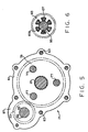
- FIG. 5 is a transverse cross section of a portion of the left motor axle assembly 17, there is illustrated the remainder of the engagement mechanism 89, i.e., the portion not shown in FIG. 4.
- the axle housing 61 of the left motor axle assembly 17 includes a shaft support portion 97 which receives and supports the end of the locking shaft 95.
- a lock gear 101 mounted on the locking shaft 95, and fixed thereto by means of a key 99 is a lock gear 101 which is in toothed engagement with the planet carrier 79 of the left gear reduction section 53.
- the ring gear 59 and manifold casting 25 cooperate to define a shaft support portion 98, configured similar to the portion 97 in FIG. 5, such that the locking shaft 95 is supported and enclosed over its full axial extent from the mechanism 87 of FIG. 4 to the left axle housing 61 of FIG. 5.
- a clutch element 103 including a cylindrical hub portion 105 which terminates at its left end in FIG. 4 in a dog clutch 107 which is permanently disposed within a plurality of openings 109 defined by the lock gear 93, whereby the clutch element 103 and lock gear 93 rotate together (see FIG. 6).
- Disposed adjacent the clutch element 103 is a clutch element 111 on which is mounted a friction element 113.
- the right end of the locking shaft 95 has a reduced diameter portion 115 which includes a plurality of external splines 117, and the clutch element 111 is in splined engagement with the external splines 117, such that the clutch element 111 can move axially relative to the locking shaft 95 but cannot rotate relative thereto.
- the clutch element 111 also includes a thrust washer 119, the function of which will be described subsequently.
- the actuation mechanism 91 is in the subject embodiment, a ball ramp cam actuator which can actuate the engagement mechanism 89 in either of two different ways.
- the mechanism 91 includes a cover plate 121 which is fixed relative to the axle housing 61 and includes a set of internal splines 123.
- an annular cam member 125 In splined engagement with the cover plate 121 is an annular cam member 125 which, because of the splined connection to the cover plate 121 is able to move axially relative to the cover plate 121, but is prevented from rotation.
- the cam member 125 is supported relative to the reduced diameter portion 115 of the locking shaft 95 by means of a needle bearing set 127.
- an annular cam ring 129 Disposed between the cam member 125 and the cover plate 121 is an annular cam ring 129, the member 125 and ring 129 cooperating to define mating ramp surfaces, between which are disposed a plurality of balls 131 (only one of which is shown in FIG. 4).
- the cam ring 129 may be manually rotated, relative to the cam member 125, by means of a handle 133.
- an annular cam ring 135. Disposed to the left of the cam ring 135 is an annular splined disk 137 having its splines in engagement with a set of external splines 139 defined by the cam member 125. Attached to the splined disk 137 is a friction disk 141, and received in a recess disposed at the left end of the cam member 125 is a radial thrust bearing set 143, which is positioned for engagement with the thrust washer 119.
- the cam member 125 and the cam ring 135 cooperate to define mating ramp surfaces, and disposed between the ramp surfaces is a plurality of cam balls 145 (only one of which is shown in FIG. 4).
- the cam ring 135 may be rotated, relative to the cam member 125, by means of a handle 147. It should be understood by those skilled in the art that some means other than the handles 133 and 147 may be used for rotating the cam rings 129 and 135. In addition, it may be desirable to have the handle (or other actuation means) biased to their unactuated position shown in FIG. 4.
- the parking brake mode of operation will be described. If the vehicle is operating on a slope, and the operator wishes to stop the vehicle and then apply a parking brake to prevent the vehicle from rolling on the slope, the operator can displace the handle 147 to rotate the cam ring 135.
- the cam member 125 does not move axially as during the locking differential mode of FIG. 8, but instead remains in the position shown in FIG. 4.
- the cam ring 135 is rotated, it "ramps up" relative to the cam member 125 on the cam balls 145, thus moving the splined disk 137 and friction disk 145 into engagement with the clutch element 111.
- the clutch element 111 and its friction element 113 are moved into frictional engagement with the clutch element 103.
- the clutch element 111 is engaged by the friction disk 141 on the spline disk 137, and because the spline disk 137 cannot rotate relative to the cam member 125 which in turn cannot rotate relative to the cover plate 121 and housing 61, the clutch elements 103 and 111 are in engagement, but are also prevented from rotating.
- the shaft 95 is splined to the clutch element 111, the left lock gear 101 is prevented from rotating, as is the right lock gear 93.
- neither lock gear 93 or 101 can rotate and therefore neither of the planet carriers 79 can rotate, thus preventing the right and left axle shafts 19 and 21 from rotating.
Landscapes
- Engineering & Computer Science (AREA)
- General Engineering & Computer Science (AREA)
- Mechanical Engineering (AREA)
- Chemical & Material Sciences (AREA)
- Combustion & Propulsion (AREA)
- Transportation (AREA)
- Motor Power Transmission Devices (AREA)
- Control Of Fluid Gearings (AREA)
- Retarders (AREA)
- Arrangement And Driving Of Transmission Devices (AREA)
Applications Claiming Priority (2)
| Application Number | Priority Date | Filing Date | Title |
|---|---|---|---|
| US769033 | 1985-08-26 | ||
| US06/769,033 US4696164A (en) | 1985-08-26 | 1985-08-26 | Hydrostatic transaxle and locking differential and brake therefor |
Publications (2)
| Publication Number | Publication Date |
|---|---|
| EP0213564A1 true EP0213564A1 (fr) | 1987-03-11 |
| EP0213564B1 EP0213564B1 (fr) | 1990-12-19 |
Family
ID=25084220
Family Applications (1)
| Application Number | Title | Priority Date | Filing Date |
|---|---|---|---|
| EP86111601A Expired - Lifetime EP0213564B1 (fr) | 1985-08-26 | 1986-08-21 | Transmission hydrostatique avec différentiation verrouillable et frein à cet effet |
Country Status (4)
| Country | Link |
|---|---|
| US (1) | US4696164A (fr) |
| EP (1) | EP0213564B1 (fr) |
| JP (1) | JPH0811490B2 (fr) |
| DE (1) | DE3676253D1 (fr) |
Families Citing this family (20)
| Publication number | Priority date | Publication date | Assignee | Title |
|---|---|---|---|---|
| AT395396B (de) * | 1987-04-28 | 1992-12-10 | Steyr Daimler Puch Ag | Antriebsanordnung fuer kraftfahrzeuge mit angetriebener vorder- und hinterachse |
| JP2535022B2 (ja) * | 1987-06-26 | 1996-09-18 | 株式会社 神崎高級工機製作所 | Hst一体形車軸駆動装置 |
| US4979583A (en) * | 1987-07-04 | 1990-12-25 | Thoma Christian H | Variable speed transaxle |
| US20030027676A1 (en) | 1991-05-28 | 2003-02-06 | Sauer-Danfoss Inc. | Axle driving apparatus |
| US4903545A (en) * | 1989-03-03 | 1990-02-27 | Sundstrand-Sauer | Hydrostatic transmission center section |
| US5087227A (en) * | 1990-06-01 | 1992-02-11 | Eaton Corporation | Hydrostatic transaxle and brake arrangement therefor |
| US5201692A (en) * | 1991-07-09 | 1993-04-13 | Hydro-Gear Limited Partnership | Rider transaxle having hydrostatic transmission |
| US5330394A (en) * | 1991-07-09 | 1994-07-19 | Hydro-Gear Limited Partnership | Rider transaxle having improved hydrostatic transmission |
| US5673776A (en) * | 1996-03-08 | 1997-10-07 | Dana Corporation | Pinion mounted parking brake |
| US6122996A (en) | 1998-11-20 | 2000-09-26 | Hydro-Gear Limited Partnership | Hydrostatic transmission |
| JP3868586B2 (ja) * | 1997-08-08 | 2007-01-17 | 株式会社 神崎高級工機製作所 | 車軸駆動装置 |
| US7454907B1 (en) | 1998-11-20 | 2008-11-25 | Hydro-Gear Limited Partnership | Hydrostatic transmission |
| US6575868B1 (en) | 2000-04-14 | 2003-06-10 | Hydro-Gear Limited Partnership | Transaxle with differential lock mechanism |
| US6616563B2 (en) * | 2000-09-04 | 2003-09-09 | Kanzaki Kokyukoki Mfg. Co., Ltd. | Transmission of working vehicle |
| US6662538B2 (en) * | 2001-08-28 | 2003-12-16 | Commerical Turf Products, Ltd. | Lawn mower main frame and sub-frame assembly |
| US6780137B1 (en) | 2002-07-26 | 2004-08-24 | Hydro-Gear Limited Partnership | Differential lock mechanism |
| EP2174816B1 (fr) * | 2008-02-13 | 2012-06-06 | Kanzaki Kokyukoki Mfg. Co., Ltd. | Dispositif de moteur de roue |
| US20100084225A1 (en) * | 2008-10-08 | 2010-04-08 | Thomas George Ore | Secondary Brake For A Work Machine Including An Adjustable Ball Ramp Assembly |
| US8820066B1 (en) * | 2009-11-13 | 2014-09-02 | Hydro-Gear Limited Partnership | Steerable transaxle |
| US11739838B2 (en) | 2021-06-02 | 2023-08-29 | Dana Graziano S.R.L. | Park lock with dog clutch and ball ramp |
Citations (8)
| Publication number | Priority date | Publication date | Assignee | Title |
|---|---|---|---|---|
| CH281003A (de) * | 1949-03-31 | 1952-02-15 | E Salzmann Willi | Differentialsperre an Traktoren. |
| CH287435A (de) * | 1949-04-08 | 1952-11-30 | Nowak Karl Ing | Einrichtung an Kraftfahrzeugen zum Hemmen des Differentials. |
| US2874790A (en) * | 1957-07-03 | 1959-02-24 | Int Harvester Co | Steering by driving with differential lock-out bull gear coupling |
| GB853197A (en) * | 1958-06-06 | 1960-11-02 | Daimler Benz Ag | Improvements relating to hydrostatic power transmission arrangements on motor vehicles |
| FR1487479A (fr) * | 1966-05-09 | 1967-07-07 | Dispositif de blocage de différentiel d'un véhicule | |
| DE1816183A1 (de) * | 1968-12-20 | 1970-06-25 | Linde Ag | Hydrostatisches Getriebe |
| DE1945439A1 (de) * | 1969-09-08 | 1971-03-11 | Linde Ag | Hydrostatisches Getriebe mit nachgeschaltetem Stufenschaltgetriebe |
| FR2478766A1 (en) * | 1980-03-24 | 1981-09-25 | Voisin Marc | External differential lock for motor vehicle - has two gears with keyed ends on common axle which descend to enmesh gears keyed to respective half-shafts |
Family Cites Families (9)
| Publication number | Priority date | Publication date | Assignee | Title |
|---|---|---|---|---|
| US2424942A (en) * | 1942-11-26 | 1947-07-29 | Der Eisenund Stahlwerke Vormal | Self-locking equalizing drive |
| CH281033A (de) * | 1947-05-08 | 1952-02-15 | Koller Ernst | Vorrichtung zur Herstellung von Eckverbindungen von Rahmen. |
| US2978929A (en) * | 1959-01-12 | 1961-04-11 | Arthur M Smith | Locking differential |
| US3474689A (en) * | 1967-05-31 | 1969-10-28 | Kenneth A Young | Torque transmitting differential |
| US3538790A (en) * | 1968-10-02 | 1970-11-10 | Gen Motors Corp | Power train |
| GB1314254A (en) * | 1970-10-08 | 1973-04-18 | Hydro Mite Ltd | Hydrostatic transmissions |
| US3814222A (en) * | 1973-01-29 | 1974-06-04 | Gen Motors Corp | Differential and brake assembly with parking brake for differential outputs |
| US4031780A (en) * | 1974-11-29 | 1977-06-28 | Chrysler Corporation | Coupling apparatus for full time four wheel drive |
| US3994354A (en) * | 1975-08-08 | 1976-11-30 | Haumaier Automotive Energy Saver, Inc. | Constant speed vehicle drive unit |
-
1985
- 1985-08-26 US US06/769,033 patent/US4696164A/en not_active Expired - Lifetime
-
1986
- 1986-08-21 EP EP86111601A patent/EP0213564B1/fr not_active Expired - Lifetime
- 1986-08-21 DE DE8686111601T patent/DE3676253D1/de not_active Expired - Lifetime
- 1986-08-26 JP JP61199870A patent/JPH0811490B2/ja not_active Expired - Lifetime
Patent Citations (8)
| Publication number | Priority date | Publication date | Assignee | Title |
|---|---|---|---|---|
| CH281003A (de) * | 1949-03-31 | 1952-02-15 | E Salzmann Willi | Differentialsperre an Traktoren. |
| CH287435A (de) * | 1949-04-08 | 1952-11-30 | Nowak Karl Ing | Einrichtung an Kraftfahrzeugen zum Hemmen des Differentials. |
| US2874790A (en) * | 1957-07-03 | 1959-02-24 | Int Harvester Co | Steering by driving with differential lock-out bull gear coupling |
| GB853197A (en) * | 1958-06-06 | 1960-11-02 | Daimler Benz Ag | Improvements relating to hydrostatic power transmission arrangements on motor vehicles |
| FR1487479A (fr) * | 1966-05-09 | 1967-07-07 | Dispositif de blocage de différentiel d'un véhicule | |
| DE1816183A1 (de) * | 1968-12-20 | 1970-06-25 | Linde Ag | Hydrostatisches Getriebe |
| DE1945439A1 (de) * | 1969-09-08 | 1971-03-11 | Linde Ag | Hydrostatisches Getriebe mit nachgeschaltetem Stufenschaltgetriebe |
| FR2478766A1 (en) * | 1980-03-24 | 1981-09-25 | Voisin Marc | External differential lock for motor vehicle - has two gears with keyed ends on common axle which descend to enmesh gears keyed to respective half-shafts |
Also Published As
| Publication number | Publication date |
|---|---|
| JPS6264625A (ja) | 1987-03-23 |
| JPH0811490B2 (ja) | 1996-02-07 |
| US4696164A (en) | 1987-09-29 |
| EP0213564B1 (fr) | 1990-12-19 |
| DE3676253D1 (de) | 1991-01-31 |
Similar Documents
| Publication | Publication Date | Title |
|---|---|---|
| US4696164A (en) | Hydrostatic transaxle and locking differential and brake therefor | |
| EP0838606B1 (fr) | Transmission de vitesse variable et unité essieu-engrenage (transaxle) | |
| US6837819B2 (en) | Transfer case with two planetary gear sets having a common carrier | |
| US4526063A (en) | Three mode differential | |
| US5984822A (en) | Integrated hydrostatic transaxle with controlled traction differential | |
| US4632207A (en) | Mechanism to engage part time drive system in a moving vehicle | |
| US6203465B1 (en) | Transfer case with four-wheel underdrive operating mode | |
| EP0392391B1 (fr) | Boîte de vitesses transversale à quatre rapports et différentiel pour véhicule automobile | |
| US4346622A (en) | Four speed transaxle with mid-position transfer drive | |
| US6033334A (en) | Transfer case having speed proportional clutch | |
| US5267915A (en) | Planetary wheel drive assembly | |
| EP1143169A2 (fr) | Dispositif de commande pour le blocage d'un différentiel | |
| US4648492A (en) | Mechanism to engage part time drive system in a moving vehicle | |
| US6935986B2 (en) | Two speed gearbox | |
| GB2097078A (en) | Parking lock arrangement for continuously variable v-belt transmission | |
| CA2030950C (fr) | Arbre de transmission sectionnel avec boite de vitesses a trois rapports | |
| CA1316371C (fr) | Engrenage differentiel | |
| EP0528547B1 (fr) | Ensemble d'entraînement en "T" | |
| US5195933A (en) | Friction drive transmission | |
| EP0459470B1 (fr) | Essieu moteur hydrostatique et dispositif de frein pour cet essieu | |
| US4722243A (en) | Vehicle transaxle and locking differential and brake assembly therefor | |
| EP0022779A1 (fr) | Moyen de direction a engrenage | |
| US4420069A (en) | Automatic clutch | |
| JP2508097B2 (ja) | 四輪駆動車用駆動装置 | |
| CA2187585C (fr) | Debrayage mecanique pour variateur de vitesse hydrostatique |
Legal Events
| Date | Code | Title | Description |
|---|---|---|---|
| PUAI | Public reference made under article 153(3) epc to a published international application that has entered the european phase |
Free format text: ORIGINAL CODE: 0009012 |
|
| AK | Designated contracting states |
Kind code of ref document: A1 Designated state(s): DE FR GB IT SE |
|
| 17P | Request for examination filed |
Effective date: 19870611 |
|
| 17Q | First examination report despatched |
Effective date: 19880629 |
|
| GRAA | (expected) grant |
Free format text: ORIGINAL CODE: 0009210 |
|
| AK | Designated contracting states |
Kind code of ref document: B1 Designated state(s): DE FR GB IT SE |
|
| ITF | It: translation for a ep patent filed |
Owner name: ING. C. GREGORJ S.P.A. |
|
| REF | Corresponds to: |
Ref document number: 3676253 Country of ref document: DE Date of ref document: 19910131 |
|
| ET | Fr: translation filed | ||
| PLBE | No opposition filed within time limit |
Free format text: ORIGINAL CODE: 0009261 |
|
| STAA | Information on the status of an ep patent application or granted ep patent |
Free format text: STATUS: NO OPPOSITION FILED WITHIN TIME LIMIT |
|
| 26N | No opposition filed | ||
| ITTA | It: last paid annual fee | ||
| EAL | Se: european patent in force in sweden |
Ref document number: 86111601.0 |
|
| PGFP | Annual fee paid to national office [announced via postgrant information from national office to epo] |
Ref country code: GB Payment date: 20000703 Year of fee payment: 15 |
|
| PGFP | Annual fee paid to national office [announced via postgrant information from national office to epo] |
Ref country code: SE Payment date: 20000802 Year of fee payment: 15 |
|
| PGFP | Annual fee paid to national office [announced via postgrant information from national office to epo] |
Ref country code: FR Payment date: 20000803 Year of fee payment: 15 |
|
| PGFP | Annual fee paid to national office [announced via postgrant information from national office to epo] |
Ref country code: DE Payment date: 20000830 Year of fee payment: 15 |
|
| PG25 | Lapsed in a contracting state [announced via postgrant information from national office to epo] |
Ref country code: GB Free format text: LAPSE BECAUSE OF NON-PAYMENT OF DUE FEES Effective date: 20010821 |
|
| PG25 | Lapsed in a contracting state [announced via postgrant information from national office to epo] |
Ref country code: SE Free format text: LAPSE BECAUSE OF NON-PAYMENT OF DUE FEES Effective date: 20010822 |
|
| EUG | Se: european patent has lapsed |
Ref document number: 86111601.0 |
|
| GBPC | Gb: european patent ceased through non-payment of renewal fee |
Effective date: 20010821 |
|
| PG25 | Lapsed in a contracting state [announced via postgrant information from national office to epo] |
Ref country code: FR Free format text: LAPSE BECAUSE OF NON-PAYMENT OF DUE FEES Effective date: 20020430 |
|
| PG25 | Lapsed in a contracting state [announced via postgrant information from national office to epo] |
Ref country code: DE Free format text: LAPSE BECAUSE OF NON-PAYMENT OF DUE FEES Effective date: 20020501 |
|
| REG | Reference to a national code |
Ref country code: FR Ref legal event code: ST |
|
| PG25 | Lapsed in a contracting state [announced via postgrant information from national office to epo] |
Ref country code: IT Free format text: LAPSE BECAUSE OF NON-PAYMENT OF DUE FEES;WARNING: LAPSES OF ITALIAN PATENTS WITH EFFECTIVE DATE BEFORE 2007 MAY HAVE OCCURRED AT ANY TIME BEFORE 2007. THE CORRECT EFFECTIVE DATE MAY BE DIFFERENT FROM THE ONE RECORDED. Effective date: 20050821 |