EP0213486A2 - Verfahren zur Betriebsbereichsanzeige einer logischen Sprache - Google Patents
Verfahren zur Betriebsbereichsanzeige einer logischen Sprache Download PDFInfo
- Publication number
- EP0213486A2 EP0213486A2 EP86111186A EP86111186A EP0213486A2 EP 0213486 A2 EP0213486 A2 EP 0213486A2 EP 86111186 A EP86111186 A EP 86111186A EP 86111186 A EP86111186 A EP 86111186A EP 0213486 A2 EP0213486 A2 EP 0213486A2
- Authority
- EP
- European Patent Office
- Prior art keywords
- procedure
- call
- term
- operation range
- clause
- Prior art date
- Legal status (The legal status is an assumption and is not a legal conclusion. Google has not performed a legal analysis and makes no representation as to the accuracy of the status listed.)
- Granted
Links
Images




Classifications
-
- G—PHYSICS
- G06—COMPUTING OR CALCULATING; COUNTING
- G06F—ELECTRIC DIGITAL DATA PROCESSING
- G06F11/00—Error detection; Error correction; Monitoring
- G06F11/36—Prevention of errors by analysis, debugging or testing of software
- G06F11/3698—Environments for analysis, debugging or testing of software
-
- G—PHYSICS
- G06—COMPUTING OR CALCULATING; COUNTING
- G06F—ELECTRIC DIGITAL DATA PROCESSING
- G06F11/00—Error detection; Error correction; Monitoring
- G06F11/30—Monitoring
- G06F11/32—Monitoring with visual or acoustical indication of the functioning of the machine
- G06F11/321—Display for diagnostics, e.g. diagnostic result display, self-test user interface
-
- G—PHYSICS
- G06—COMPUTING OR CALCULATING; COUNTING
- G06F—ELECTRIC DIGITAL DATA PROCESSING
- G06F11/00—Error detection; Error correction; Monitoring
- G06F11/30—Monitoring
- G06F11/32—Monitoring with visual or acoustical indication of the functioning of the machine
- G06F11/323—Visualisation of programs or trace data
-
- G—PHYSICS
- G06—COMPUTING OR CALCULATING; COUNTING
- G06F—ELECTRIC DIGITAL DATA PROCESSING
- G06F8/00—Arrangements for software engineering
- G06F8/30—Creation or generation of source code
- G06F8/31—Programming languages or programming paradigms
- G06F8/313—Logic programming, e.g. PROLOG programming language
Definitions
- the present invention relates to a test and debug support method for a logical language, and in particular to an operation range display method of program suitable to the test and debug based upon declarative program understanding.
- operation grasp models for each clause taken as a unit, for each head term of a clause taken as a unit, and for each body term of a clause taken as a unit are proposed in a paper entitled “Function and Effect of Logical Basic Processing system LONLI” presented by Hirose et al. at the 29th National Conference of the Information Processing Society of Japan (l984).
- FIG. l For example, an example of programming using the logical language PROLOG as shown in Fig. l is assumed.
- a program d-letter (X) determines whether a part of the list includes two consecutive identical elements or two alternate identical elements. This program is more easily understood by using the declarative understanding method described below. A number of programmers produce programs on the basis of this understanding method.
- Fig. 2 shows an example of display of the operation path when the "clause" model is used.
- Arrows in Fig. 2 faithfully show the processing procedure of the processing system of the logical language prolog. That is to say, the arrows are displays corresponding to the procedural understanding method. It is difficult to make these displays correspond to understanding of the above described (clause l), (clause 2) and (clause 3), i.e., the declarative understanding method. Because the displayed entire operation path extending from the program start to the program end must be tracked for reading out of the display of Fig. 2 the necessary information representing which clause has been used.
- An object of the present invention is to provide a program operation range display method suitable to the test and debugging work based upon the declarative program understanding of the program described by the logical language.
- the present invention is based upon the fact that the principal information used in the declarative understanding method is the cumulative information obtained by overlapping the operation paths extending from the program start to the program end for each procedure, each head term and each body term.
- the operation range is displayed for each procedure, each head term and each body term.
- Fig. 3 shows an example of display according to the present invention when the execution as shown in Fig. 2 has been conducted.
- the displays are associated with four sides of box-shaped figures surrounding respective terms and are easy for programmers knowing the conventional operation path display (Fig. 2) to learn.
- Fig. 4 shows the block configuration of entire system whereto the present invention is applied.
- An arithmetic unit 3l, a memory unit 32, a CRT display unit 33, and a keyboard input unit 34 are connected via a bus 35.
- Fig. 5 shows the configuration of software of this embodiment stored in the memory unit 32.
- a control section 4l, an input/output section 42, an inference section 43, a debugger display section 44, a user program section 46 and an execution management stack section 47 are included in the software configuration.
- the control section 4l is at first activated by a system start signal 45.
- the control section 4l analyzes a command 4ll supplied from the keyboard input unit 34 by the user and issues either a signal 45l for activating the input/output section 42 or a signal 452 for activating the inference section 43.
- the input/output section 42 stores a program 42l supplied by the user into the user program section 46.
- the inference section 43 refers to the user program section 46, and produces a solution to a question supplied by the user while using the execution management stack section 47.
- the debugger display section 44 successively supervises the progress of processing conducted in the inference section 43 and sends the supervision result 442 to the user.
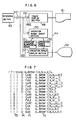
- the operation of the debugger display section 44 will now be described by referring to Fig. 6.
- the debugger display section 44 includes a trace display section 49, an operation range grasp section 50, an operation situation supervision stack 5l, an operation range table 52, and an operation range display section 53.
- the inference section 43 produces a starting signal 49l for the trace display section 49 and the operation range grasp section 50 at the time when the "clause mode" passes through the control point.
- the inference section sends out a signal 492 relating to a class 7l of a transit point shown in Fig. 7, a procedure name 72 during execution, a consistent call number 73 generated whenever a procedure call is produced, and a call level 74 for indicating the nest level of the call.
- the trace display section 49 traces the signal 492 to successively send out the trace display result 6l.
- Fig. 7 shows output examples of trace displays resulting from applying the operation shown in Fig. 2 to the program of Fig. l.
- the operation range grasp section 50 grasps operations executed for each procedure, each head term, and each body term, and records them on the operation range table 52.
- the inference section 43 sends out a start signal 53l to start the operation range display section 53.
- the operation range display section 53 displays the operation ranges of each procedure, each head term and each body term on a display 62 by making thick only sides which have actually been activated among upper, right, left and lower sides of box-shaped figures surrounding each procedure, each head term, and each body term.
- Fig. 3 shows a display example of operation range for the procedure d-letter (X) derived after the operation shown in Fig. 2.
- Fig. 8A shows the detailed structure of the operation situation supervision stack 5l.
- Fig. 8B shows the detailed structure of the operation range table 52.
- the operation situation supervision stack 5l stores therein a record 77 composed of six kinds of information.
- the six kinds of information are a call procedure name 72, a consistent call number 73, a control point class 7l distinguishing between call (hereafter referred to as C), exit (successful end, hereafter referred to as E), redo (recall, hereafter referred to as R), and tail (unsuccessful end, hereafter referred to as F), a call level 74, a current clause number 75 (hereafter referred to as L number) representing the number of clause now under execution, and a current term number 76 (hereafter referred to as C number) representing the number of term now under execution.
- L number current clause number
- C number current term number
- the operation range table 52 is composed of a collection of records 80.
- the record 80 is composed of the procedure name 72 and an arrangement 79 of four kinds of operation flags (C-E, C-F, R-E and R-F flags) for each term (head term and body term) of each clause included in that procedure.
- the C-E, C-F, R-E and R-F flags are l-bit flags set to "l" when C-E, C-F, R-E and R-F operation has been effected upon the corresponding term, respectively.
- the operation range grasp section 50 is activated by the inference section 43 when the control point in the "clause model" of the program is passed through. Then the section 50 performs the processing as follows.
- Figs. l0A and l0B respectively show the contents of the operation situation supervision stack 5l and the operation range table 52 when the operation range grasp section 50 has processed the first information to the eighth information shown in Fig. 7. Since the L number 75 and C number 76 of the first record of the operation situation supervision stack 5l are respectively 3 and 2, it is known that the call source of the second record is the second term of the third clause of the procedure d-letter.
- Fig. ll shows another example of display of program execution range derived by the present embodiment.
- the first clause is not used, and back tracking is incurred between s (X, Y) and r (A, Y) of the third clause. It is also understood that recall for this predicate has not been effected, and the call for the predicate has not brought about unsuccessful end.
- the display of the operation range agrees with the declarative understanding method of the program described by a logical language, i.e., the program understanding method based on the standpoint that each procedure and each clause represent identical facts. That is to say, identical facts which have been used are displayed. As a result, the efficiency in test and debugging work is improved.
Landscapes
- Engineering & Computer Science (AREA)
- Theoretical Computer Science (AREA)
- General Engineering & Computer Science (AREA)
- Physics & Mathematics (AREA)
- General Physics & Mathematics (AREA)
- Software Systems (AREA)
- Quality & Reliability (AREA)
- Computing Systems (AREA)
- Computer Hardware Design (AREA)
- Data Mining & Analysis (AREA)
- Human Computer Interaction (AREA)
- Debugging And Monitoring (AREA)
- Devices For Executing Special Programs (AREA)
Applications Claiming Priority (2)
| Application Number | Priority Date | Filing Date | Title |
|---|---|---|---|
| JP60195848A JPH079628B2 (ja) | 1985-09-06 | 1985-09-06 | 論理型言語の動作範囲表示方法 |
| JP195848/85 | 1985-09-06 |
Publications (3)
| Publication Number | Publication Date |
|---|---|
| EP0213486A2 true EP0213486A2 (de) | 1987-03-11 |
| EP0213486A3 EP0213486A3 (en) | 1989-05-10 |
| EP0213486B1 EP0213486B1 (de) | 1995-06-21 |
Family
ID=16348014
Family Applications (1)
| Application Number | Title | Priority Date | Filing Date |
|---|---|---|---|
| EP86111186A Expired - Lifetime EP0213486B1 (de) | 1985-09-06 | 1986-08-12 | Verfahren zur Betriebsbereichsanzeige einer logischen Sprache |
Country Status (4)
| Country | Link |
|---|---|
| US (1) | US4794529A (de) |
| EP (1) | EP0213486B1 (de) |
| JP (1) | JPH079628B2 (de) |
| DE (1) | DE3650337T2 (de) |
Cited By (1)
| Publication number | Priority date | Publication date | Assignee | Title |
|---|---|---|---|---|
| WO1995002863A1 (de) * | 1993-07-15 | 1995-01-26 | Siemens Aktiengesellschaft | Verfahren zum test eines objektorientierten programms |
Families Citing this family (2)
| Publication number | Priority date | Publication date | Assignee | Title |
|---|---|---|---|---|
| JP2696210B2 (ja) * | 1987-03-20 | 1998-01-14 | 株式会社日立製作所 | 論理型言語プログラムの実行トレース表示方法 |
| US4943968A (en) * | 1987-03-04 | 1990-07-24 | Hitachi, Ltd. | Method of displaying execution trace in a logic programming language processing system |
Family Cites Families (1)
| Publication number | Priority date | Publication date | Assignee | Title |
|---|---|---|---|---|
| US4481602A (en) * | 1981-04-06 | 1984-11-06 | International Business Machines Corporation | Font compression and decompression for character generation |
-
1985
- 1985-09-06 JP JP60195848A patent/JPH079628B2/ja not_active Expired - Lifetime
-
1986
- 1986-08-12 EP EP86111186A patent/EP0213486B1/de not_active Expired - Lifetime
- 1986-08-12 DE DE3650337T patent/DE3650337T2/de not_active Expired - Fee Related
- 1986-08-13 US US06/895,954 patent/US4794529A/en not_active Expired - Fee Related
Non-Patent Citations (4)
| Title |
|---|
| IEEE PROCEEDINGS, THE 14TH CONVENTION OF ELECTRICAL & ELECTRONICS ENGINEERS IN ISRAEL, Tel Aviv, 26th - 28th March 1985, paper 3.2.5, pages 1-5; J. KATZENELSON et al.: "SDE: a symbolic debugger for macro-oriented data abstractions" * |
| INTERNATIONAL SYMPOSIUM ON NEW DIRECTIONS IN COMPUTING, Trondheim, 12th - 14th August 1985, pages 344-351, IEEE; M. MORAN et al.: "Toward graphical animated debugging of concurrent programs in ADA" * |
| PROCEEDINGS OF THE 8TH INTERNATIONAL CONFERENCE ON SOFTWARE ENGINEERING, London, 28th - 30th August 1985, pages 320-325, IEEE; N. DE FRANCESCO et al.: "An interactive debugger for a concurrent language" * |
| PROCEEDINGS OF THE ACM SIGPLAN 85: SYMPOSIUM ON LANGUAGE ISSUES IN PROGRAMMING ENVIRONMENTS, Seattle, WA, 25th - 28th June 1985, vol. 20, no. 7, July 1985, pages 179-190, ACM; N. FRANCEZ et al.: "An enviroment for logic programming" * |
Cited By (1)
| Publication number | Priority date | Publication date | Assignee | Title |
|---|---|---|---|---|
| WO1995002863A1 (de) * | 1993-07-15 | 1995-01-26 | Siemens Aktiengesellschaft | Verfahren zum test eines objektorientierten programms |
Also Published As
| Publication number | Publication date |
|---|---|
| JPH079628B2 (ja) | 1995-02-01 |
| JPS6257033A (ja) | 1987-03-12 |
| EP0213486A3 (en) | 1989-05-10 |
| DE3650337T2 (de) | 1996-03-07 |
| US4794529A (en) | 1988-12-27 |
| EP0213486B1 (de) | 1995-06-21 |
| DE3650337D1 (de) | 1995-07-27 |
Similar Documents
| Publication | Publication Date | Title |
|---|---|---|
| US5732277A (en) | Graphical system for modelling a process and associated method | |
| JPH04337843A (ja) | プログラム動作表示方法 | |
| JPH02232152A (ja) | 生産システムシミュレータ生成装置 | |
| Duisberg | Visual programming of program visualizations: a gestural interface for animating algorithms | |
| US4794529A (en) | Method for displaying operation range of logical language | |
| JPH0120771B2 (de) | ||
| JPH02275539A (ja) | デバッグ処理方式 | |
| JPH09330212A (ja) | プログラミング言語処理システム | |
| Addison et al. | Manuals as structured programs | |
| Cox et al. | Advanced programming aids in PROGRAPH | |
| JPS6254337A (ja) | プログラムの階層指定表示方式 | |
| JPH0731309Y2 (ja) | シミュレ−ション機能を備える情報処理装置 | |
| JPH04274519A (ja) | プログラム高速化自動実行方式 | |
| Diederich et al. | NEMISYS: An expert-system for nematode identification | |
| JPS61220061A (ja) | プロセス制御系向きブロツク図形式シミユレ−タ・システム | |
| JPS58223837A (ja) | 端末機のブロツクガイダンス制御方式 | |
| JPH0749935A (ja) | 画像処理の装置及び方法 | |
| JPH01288930A (ja) | 離散事象型シミュレーション方式 | |
| Beicky et al. | Tools for Validation of CBL Principles | |
| JPS6186846A (ja) | プログラムデバツグ装置 | |
| JPH0724022B2 (ja) | プログラム言語変換方法 | |
| JPH01123369A (ja) | プレゼンテーション装置 | |
| JPH01291328A (ja) | インタプリタ形言語システム | |
| CN114035767A (zh) | 一种tec-xp16组合逻辑控制器指令设计方法 | |
| JPS62117042A (ja) | 情報処理装置の試験方法 |
Legal Events
| Date | Code | Title | Description |
|---|---|---|---|
| PUAI | Public reference made under article 153(3) epc to a published international application that has entered the european phase |
Free format text: ORIGINAL CODE: 0009012 |
|
| AK | Designated contracting states |
Kind code of ref document: A2 Designated state(s): DE FR GB |
|
| PUAL | Search report despatched |
Free format text: ORIGINAL CODE: 0009013 |
|
| AK | Designated contracting states |
Kind code of ref document: A3 Designated state(s): DE FR GB |
|
| 17P | Request for examination filed |
Effective date: 19891027 |
|
| 17Q | First examination report despatched |
Effective date: 19920205 |
|
| GRAA | (expected) grant |
Free format text: ORIGINAL CODE: 0009210 |
|
| AK | Designated contracting states |
Kind code of ref document: B1 Designated state(s): DE FR GB |
|
| REF | Corresponds to: |
Ref document number: 3650337 Country of ref document: DE Date of ref document: 19950727 |
|
| ET | Fr: translation filed | ||
| PLBE | No opposition filed within time limit |
Free format text: ORIGINAL CODE: 0009261 |
|
| STAA | Information on the status of an ep patent application or granted ep patent |
Free format text: STATUS: NO OPPOSITION FILED WITHIN TIME LIMIT |
|
| 26N | No opposition filed | ||
| PGFP | Annual fee paid to national office [announced via postgrant information from national office to epo] |
Ref country code: FR Payment date: 19980616 Year of fee payment: 13 |
|
| PGFP | Annual fee paid to national office [announced via postgrant information from national office to epo] |
Ref country code: GB Payment date: 19980731 Year of fee payment: 13 |
|
| PGFP | Annual fee paid to national office [announced via postgrant information from national office to epo] |
Ref country code: DE Payment date: 19981027 Year of fee payment: 13 |
|
| PG25 | Lapsed in a contracting state [announced via postgrant information from national office to epo] |
Ref country code: GB Free format text: LAPSE BECAUSE OF NON-PAYMENT OF DUE FEES Effective date: 19990812 |
|
| GBPC | Gb: european patent ceased through non-payment of renewal fee |
Effective date: 19990812 |
|
| PG25 | Lapsed in a contracting state [announced via postgrant information from national office to epo] |
Ref country code: FR Free format text: LAPSE BECAUSE OF NON-PAYMENT OF DUE FEES Effective date: 20000428 |
|
| PG25 | Lapsed in a contracting state [announced via postgrant information from national office to epo] |
Ref country code: DE Free format text: LAPSE BECAUSE OF NON-PAYMENT OF DUE FEES Effective date: 20000601 |
|
| REG | Reference to a national code |
Ref country code: FR Ref legal event code: ST |