EP0212262A2 - Anordnung eines Handbremshebels in einem Kraftfahrzeug - Google Patents
Anordnung eines Handbremshebels in einem Kraftfahrzeug Download PDFInfo
- Publication number
- EP0212262A2 EP0212262A2 EP86109798A EP86109798A EP0212262A2 EP 0212262 A2 EP0212262 A2 EP 0212262A2 EP 86109798 A EP86109798 A EP 86109798A EP 86109798 A EP86109798 A EP 86109798A EP 0212262 A2 EP0212262 A2 EP 0212262A2
- Authority
- EP
- European Patent Office
- Prior art keywords
- arrangement according
- hand brake
- handle
- brake lever
- armrest
- Prior art date
- Legal status (The legal status is an assumption and is not a legal conclusion. Google has not performed a legal analysis and makes no representation as to the accuracy of the status listed.)
- Granted
Links
Images

Classifications
-
- B—PERFORMING OPERATIONS; TRANSPORTING
- B60—VEHICLES IN GENERAL
- B60T—VEHICLE BRAKE CONTROL SYSTEMS OR PARTS THEREOF; BRAKE CONTROL SYSTEMS OR PARTS THEREOF, IN GENERAL; ARRANGEMENT OF BRAKING ELEMENTS ON VEHICLES IN GENERAL; PORTABLE DEVICES FOR PREVENTING UNWANTED MOVEMENT OF VEHICLES; VEHICLE MODIFICATIONS TO FACILITATE COOLING OF BRAKES
- B60T7/00—Brake-action initiating means
- B60T7/02—Brake-action initiating means for personal initiation
- B60T7/08—Brake-action initiating means for personal initiation hand actuated
- B60T7/10—Disposition of hand control
- B60T7/102—Disposition of hand control by means of a tilting lever
-
- B—PERFORMING OPERATIONS; TRANSPORTING
- B60—VEHICLES IN GENERAL
- B60N—SEATS SPECIALLY ADAPTED FOR VEHICLES; VEHICLE PASSENGER ACCOMMODATION NOT OTHERWISE PROVIDED FOR
- B60N2/00—Seats specially adapted for vehicles; Arrangement or mounting of seats in vehicles
- B60N2/75—Arm-rests
- B60N2/79—Adaptations for additional use of the arm-rests
Definitions
- the invention relates to the arrangement of a handbrake lever in a motor vehicle, which is pivotally mounted about a transverse axis next to a vehicle seat and is provided with a handle at the front end.
- Handbrake levers of this type are widely known. Hand brake levers are already known (DE-PS 27 08 993, vehicles of the "Alfa 90" type) which have a transverse handle. In the last-mentioned case, a storage tray located in the area of the hand brake lever is also provided with a padded cover.
- the invention has for its object to provide an arrangement and design of a hand brake lever for a motor vehicle fen, which ensures good grip of the handbrake lever, offers good support for the driver's arm and is stylish.
- the handbrake lever is designed as an armrest in its area behind the handle.
- the armrest which also forms the handbrake lever, is then generally swiveled up and is then no longer required as an armrest when the driver parks and leaves the vehicle. If the vehicle is put into operation again and the handbrake is released, the armrest integrated in the handbrake lever is again in the position in which it can fully perform its function as an armrest, namely in the essentially horizontal rest position.
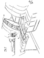
- the handbrake lever 1 for a motor vehicle shown in FIG. 1 of the drawing is arranged next to the vehicle seat 2 intended for the driver and is pivotably mounted about a transverse axis 3. It is also provided with a handle 4 at the front end.
- the hand brake lever 1 is designed as an armrest 5 in its area behind the handle. As can also be seen, the hand brake lever 1 has a transverse handle 4 and the armrest support 6 has approximately the width b of the handle 4 and adjoins the handle 4 directly.
- the handle 4 is designed as a flat handle 7, which has a release button 8 in the middle for unlocking the hand brake lever 1.
- the handle 4' is directed downward at the front. In this way, the shift lever / can be gripped better and, if necessary, push buttons 10 or the like which are present in this area can also be better reached.
- the entire hand brake lever 1 or 1 ' has approximately the width of the armrest support 6 or 6'. It is therefore essentially designed as a box-shaped or U-shaped component.
- a second armrest 11 or 11' for the passenger is arranged on the passenger side immediately next to the handbrake lever 1 or 1 ', with the armrest 5 or 5' of the handbrake lever 1 or 1 1 - at least in side view - is largely the same shape.
- the second armrest 11 or 11 ' is designed as a cover for a storage tray 12 which is located next to the hand brake lever 1.
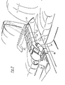
- This cover that is to say the second armrest 11, can be pivoted upward about an axis which is coaxial with the pivot axis 3 of the hand brake lever 1, as can be seen in FIG. 2. She is in the upwardly pivoted position in side view approximately the same contour as the adjacent seat back 13 of the front passenger seat.
- the second armrest 11 forming the cover is subdivided on its underside into compartments 14, 15, which can optionally also be designed for more stable mounting of glasses or the like.
- the second armrest 11 which forms the cover of the storage tray 12, can also be lockable, for example with a key. It can also be locked in such a way that it is locked electromagnetically or similarly when the ignition key is removed.
- the cover also ensures that, for example in the case of an open passenger car designed as a convertible, the objects stored in the storage tray 12 are not only secured against theft, but are also protected against rain or dust.
Landscapes
- Engineering & Computer Science (AREA)
- Transportation (AREA)
- Mechanical Engineering (AREA)
- Aviation & Aerospace Engineering (AREA)
- Seats For Vehicles (AREA)
- Braking Elements And Transmission Devices (AREA)
Abstract
Description
- Die Erfindung bezieht sich auf die Anordnung eines Handbremshebels in einem Kraftfahrzeug, der neben einem Fahrzeugsitz um eine Querachse schwenkbar gelagert und am vorderen Ende mit einem Griff versehen ist.
- Derartige Handbremshebel sind vielfach bekannt. Es sind auch schon Handbremshebel bekannt (DE-PS 27 08 993, Fahrzeuge des Typs "Alfa 90"), die einen querverlaufenden Griff haben. In dem zuletzt erwähnten Fall ist auch schon eine im Bereich des Handbremshebels gelegene Ablageschale mit einer gepolsterten Abdeckung versehen.
- Die bekannten Anordnungen und Ausbildungen eines Handbremshebels und einer Armstütze haben den Nachteil, daß sie sich gegenseitig in dem für ihre Funktion erforderlichen Bauraum ungünstig beeinflussen. Ist die Armsützte genügend groß, so verbleibt für den Handbremshebel nur mehr wenig Raum, weshalb seine Zugänglichkeit beeinträchtigt ist. Wird dagegen auf gute Ergreifbarkeit des Handbremshebels größerer Wert gelegt, so hat die gepolsterte Abdeckung der Ablageschale nur eine unzureichende Größe, um als gute Armstütze fungieren zu können.
- Der Erfindung liegt die Aufgabe zugrunde, eine Anordnung und Ausbildung eines Handbremshebels für ein Kraftfahrzeug zu schaffen, die eine gute Ergreifbarkeit des Handbremshebels gewährleistet, eine gute Abstützmöglichkeit für den Arm des Fahrers bietet und stilistisch ansprechend ist.
- Diese Aufgabe wird mit einem Handbremshebel der eingangs erwähnten Gattung dadurch gelöst, daß der Handbremshebel in seinem hinter dem Griff liegenden Bereich als Armstütze ausgebildet ist. Auf diese Weise braucht bei der Dimensionierung der Armstütze nicht auf die Platzierung und Ausbildung des (im Stand der Technik separaten) Handbremshebels so viel Rücksicht genommen zu werden. Die Armstütze, die zugleich den Handbremshebel bildet, wird in der Regel dann hochgeschwenkt und ist dann als Armstütze nicht mehr vonnöten, wenn der Fahrer das Fahrzeug abstellt und verläßt. Wird das Fahrzeug wieder in Betrieb genommen und die Handbremse gelöst, so befindet sich die in den Handbremshebel integrierte Armstütze wieder in der Position, in der sie als Armstütze ihre Funktion voll erfüllen kann, nämlich in der im wesentlichen waagrechten Ruhelage.
- Mehrere Ausführungsbeispiele der Erfindung und zweckmäßige Weiterbildungen sind im folgenden anhand der Zeichnung näher erläutert. Es zeigen
- Fig. 1 die perspektivische Ansicht eines ersten Ausführungsbeispiels der Erfindung;
- Fig. 2 eine der Fig. 1 entsprechende Ansicht, jedoch mit hochgeklappter Beifahrer-Armstütze und
- Fig. 3 eine der Fig. 1 entsprechende Ansicht eines etwas abgewandelten Ausführungsbeispiels.
- Der in Fig. 1 der Zeichnung dargestellte Handbremshebel 1 für ein Kraftfahrzeug ist neben dem für den Fahrer bestimmten Fahrzeugsitz 2 angeordnet und um eine Querachse 3 schwenkbar gelagert. Er ist ferner am vorderen Ende mit einem Griff 4 versehen.
- Der Handbremshebel 1 ist in seinem hinter dem Griff liegenden Bereich als Armstütze 5 ausgebildet. Wie man ferner erkennt hat der Handbremshebel 1 einen querverlaufenden Griff 4 und die Armstützenauflage 6 weist etwa die Breite b des Griffes 4 auf und schließt sich unmittelbar an dem Griff 4 an. Der Griff 4 ist als flächige Handhabe 7 ausgebildet, die in der Mitte eine Lösetaste 8 zum entriegeln des Handbremshebels 1 aufweist.
- Bei dem in Fig. 3 dargestellten Ausführungsbeispiel eines Handbremshebels 1' ist der Griff 4' nach vorne unten gerichtet. Auf diese Weise läßt sich der Schalthebel/besser ergreifen und auch gegebenenfalls in diesem Bereich vorhandene Drucktasten 10 oder ähnliches besser erreichen.
- Bei den in der Zeichnung dargestellten Ausführungsbeispielen hat der gesamte Handbremshebel 1 bzw. l' etwa die Breite der Armstützenauflage 6 bzw. 6'. Er ist daher im wesentlichen als kastenförmiges oder U-förmiges Bauteil ausgebildet.
- Bei der bevorzugten Anordnung und Ausbildung der Handbremshebel 1 bzw. 1' ist auf der Beifahrerseite unmittelbar neben dem Handbremshebel 1 bzw. 1' eine zweite Armstütze 11 bzw. 11' für den Beifahrer angeordnet die mit der Armstütze 5 bzw. 5' des Handbremshebels 1 bzw. 11 - zumindest in Seitenansicht - weitgehend konturengleich ist. Die zweite Armstütze 11 bzw. 11' ist als Abdeckung einer Ablageschale 12 ausgebildet, die sich neben dem Handbremshebel 1 befindet. Diese Abdeckung, also die zweite Armstütze 11, ist um eine zur Schwenkachse 3 des Handbremshebels 1 koaxiale Achse nach oben schwenkbar, wie man in Fig. 2 erkennt. Sie ist in der nach oben geschwenkten Stellung in Seitenansicht etwa konturengleich mit der angrenzenden Sitzlehne 13 des Beifahrersitzes.
- Die die Abdeckung bildende zweite Armstütze 11 ist an ihrer Unterseite in Fächer 14, 15 unterteilt, die gegebenenfalls auch zur stabileren Halterung von Gläsern oder ähnlichem ausgebildet sein können.
- Die zweite Armstütze 11, die die Abdeckung der Ablegeschale 12 bildet, kann auch verschließbar sein, etwa mit einem Schlüssel. Sie kann auch in der Weise verriegelt sein, daß sie bei abgezogenem Zündschlüssel elektromagnetisch oder ähnlich verriegelt ist. Die Abdeckung gewährleistet schließlich noch, daß beispielsweise bei einem offenen, als Cabrio ausgebildeten Personenkaftwagen die in der Ablegeschale 12 aufbewahrten Gegenstände nicht nur gegen Diebstahl gesichert, sondern auch vor Regen oder Staub geschützt sind.
Claims (12)
Applications Claiming Priority (2)
| Application Number | Priority Date | Filing Date | Title |
|---|---|---|---|
| DE3528568 | 1985-08-08 | ||
| DE3528568A DE3528568C1 (de) | 1985-08-08 | 1985-08-08 | Anordnung eines Handbremshebels in einem Kraftfahrzeug |
Publications (3)
| Publication Number | Publication Date |
|---|---|
| EP0212262A2 true EP0212262A2 (de) | 1987-03-04 |
| EP0212262A3 EP0212262A3 (en) | 1987-09-02 |
| EP0212262B1 EP0212262B1 (de) | 1988-12-21 |
Family
ID=6278086
Family Applications (1)
| Application Number | Title | Priority Date | Filing Date |
|---|---|---|---|
| EP86109798A Expired EP0212262B1 (de) | 1985-08-08 | 1986-07-17 | Anordnung eines Handbremshebels in einem Kraftfahrzeug |
Country Status (2)
| Country | Link |
|---|---|
| EP (1) | EP0212262B1 (de) |
| DE (2) | DE3528568C1 (de) |
Cited By (5)
| Publication number | Priority date | Publication date | Assignee | Title |
|---|---|---|---|---|
| FR2724609A1 (fr) * | 1994-09-20 | 1996-03-22 | Peugeot | Agencement combine pour console disposee entre les sieges avant d'un vehicule automobile |
| FR2798343A1 (fr) | 1999-09-10 | 2001-03-16 | Renault | Levier de frein a main pour vehicule automobile |
| EP1083092A3 (de) * | 1999-09-08 | 2002-02-27 | Volkswagen Aktiengesellschaft | Mitteltunnel eines Kraftfahrzeugs |
| DE10355895A1 (de) * | 2003-11-29 | 2005-06-30 | Daimlerchrysler Ag | Armstütze |
| DE102008056628A1 (de) * | 2008-11-10 | 2009-08-20 | Audi Ag | Ablagefach für die Aufbewahrung einer Brille in einem Kraftfahrzeug |
Families Citing this family (6)
| Publication number | Priority date | Publication date | Assignee | Title |
|---|---|---|---|---|
| AT403146B (de) * | 1996-03-06 | 1997-11-25 | Dallamassl Franz | Handbremshebel für die feststellbremse von fahrzeugen, insbesondere von personenkraftwagen |
| DE10029750C1 (de) | 2000-06-16 | 2001-11-15 | Edscha Ag | Feststellbremse |
| DE10236129A1 (de) * | 2002-08-07 | 2004-02-26 | Daimlerchrysler Ag | Handbremshebelgriff als Armauflage |
| DE102007006198A1 (de) * | 2007-02-08 | 2008-08-14 | GM Global Technology Operations, Inc., Detroit | Mittelkonsole |
| DE102010004369B4 (de) * | 2010-01-12 | 2018-07-05 | Audi Ag | Lösbares Ablagebehältnis für die Aufbewahrung eines Gegenstandes, insbesondere einer Brille oder eines Mobiltelefons in einem Kraftfahrzeug |
| CN106004582B (zh) * | 2016-05-24 | 2018-12-21 | 上汽通用汽车有限公司 | 中央扶手组件 |
Citations (4)
| Publication number | Priority date | Publication date | Assignee | Title |
|---|---|---|---|---|
| DE1108085B (de) * | 1958-07-26 | 1961-05-31 | Daimler Benz Ag | Getriebeschaltvorrichtung fuer Kraftfahrzeuge |
| DE1220266B (de) * | 1963-08-27 | 1966-06-30 | Hermann K Weihe | Handgasbetaetigungsvorrichtung, insbesondere fuer Kraftfahrzeuge |
| DE1813417A1 (de) * | 1967-12-22 | 1969-07-03 | Lueck Arthur M | Armstuetze fuer Kraftfahrzeuge |
| DE2708993C2 (de) * | 1977-03-02 | 1981-09-17 | Bayerische Motoren Werke AG, 8000 München | Anordnung eines Handhebels für die Feststellbremse von Kraftfahrzeugen, insbesondere von Personenkraftwagen |
-
1985
- 1985-08-08 DE DE3528568A patent/DE3528568C1/de not_active Expired
-
1986
- 1986-07-17 DE DE8686109798T patent/DE3661469D1/de not_active Expired
- 1986-07-17 EP EP86109798A patent/EP0212262B1/de not_active Expired
Patent Citations (4)
| Publication number | Priority date | Publication date | Assignee | Title |
|---|---|---|---|---|
| DE1108085B (de) * | 1958-07-26 | 1961-05-31 | Daimler Benz Ag | Getriebeschaltvorrichtung fuer Kraftfahrzeuge |
| DE1220266B (de) * | 1963-08-27 | 1966-06-30 | Hermann K Weihe | Handgasbetaetigungsvorrichtung, insbesondere fuer Kraftfahrzeuge |
| DE1813417A1 (de) * | 1967-12-22 | 1969-07-03 | Lueck Arthur M | Armstuetze fuer Kraftfahrzeuge |
| DE2708993C2 (de) * | 1977-03-02 | 1981-09-17 | Bayerische Motoren Werke AG, 8000 München | Anordnung eines Handhebels für die Feststellbremse von Kraftfahrzeugen, insbesondere von Personenkraftwagen |
Cited By (5)
| Publication number | Priority date | Publication date | Assignee | Title |
|---|---|---|---|---|
| FR2724609A1 (fr) * | 1994-09-20 | 1996-03-22 | Peugeot | Agencement combine pour console disposee entre les sieges avant d'un vehicule automobile |
| EP1083092A3 (de) * | 1999-09-08 | 2002-02-27 | Volkswagen Aktiengesellschaft | Mitteltunnel eines Kraftfahrzeugs |
| FR2798343A1 (fr) | 1999-09-10 | 2001-03-16 | Renault | Levier de frein a main pour vehicule automobile |
| DE10355895A1 (de) * | 2003-11-29 | 2005-06-30 | Daimlerchrysler Ag | Armstütze |
| DE102008056628A1 (de) * | 2008-11-10 | 2009-08-20 | Audi Ag | Ablagefach für die Aufbewahrung einer Brille in einem Kraftfahrzeug |
Also Published As
| Publication number | Publication date |
|---|---|
| EP0212262B1 (de) | 1988-12-21 |
| DE3528568C1 (de) | 1987-01-15 |
| DE3661469D1 (en) | 1989-01-26 |
| EP0212262A3 (en) | 1987-09-02 |
Similar Documents
| Publication | Publication Date | Title |
|---|---|---|
| DE3143957C2 (de) | Mittelarmlehne für die Vordersitze eines Kraftfahrzeuges | |
| DE3420574C2 (de) | ||
| EP0212262B1 (de) | Anordnung eines Handbremshebels in einem Kraftfahrzeug | |
| DE2848268C2 (de) | ||
| EP0946376A1 (de) | Tischeinrichtung für einen kraftfahrzeugsitz | |
| EP0710585A1 (de) | Transportvorrichtung für Kraftfahrzeuge, wie z.B. für Kombinationskraftwagen oder Grossraum-Personenkraftwagen | |
| DE102007020190A1 (de) | Fahrzeugsitz mit Staufach | |
| EP0286038B1 (de) | Ablage für Kraftfahrzeuge, insbesondere im Tunnelbereich eines Lastkraftwagens zwischen Fahrer- und Beifahrersitz | |
| EP0084107B1 (de) | Elektrisch verstellbarer Fahrzeugsitz | |
| DE60309302T2 (de) | Machienensteuerungsvorrichtung und Verfahren | |
| DE3539258C2 (de) | Hintersitzanordnung in einem Kraftfahrzeug mit aus der Rückenlehne herausklappbarer Armlehne | |
| DE112006001302T5 (de) | Kopfstütze für ein Cabrio-Kraftfahrzeug | |
| DE102020207456A1 (de) | Mittelkonsole für ein Kraftfahrzeug | |
| EP1258397A2 (de) | Aufnahmevorrichtung für einen Laderaum eines Kraftfahrzeuges | |
| DE19518393C2 (de) | Kraftfahrzeug | |
| DE3729642A1 (de) | Ruecksitzanordnung mit kopfstuetze fuer kraftfahrzeuge | |
| DE19607398C1 (de) | Handbetätigte Stellvorrichtung für einen Bedienungssitz eines Flurförderzeugs | |
| EP0589188A1 (de) | Personenkraftwagen mit einem zusätzlichen Stauraum | |
| EP0960777B1 (de) | Fahrzeug mit einem Ablagefach | |
| DE10220029A1 (de) | Windschott für ein Cabriolet | |
| DE10238888B4 (de) | Fahrzeugsitz mit zugeordnetem Laderaum | |
| DE102014000026A1 (de) | Verstellbare Armlehne für ein Fahrzeug sowie Fahrzeug mit mindestens einer derartigen Armlehne | |
| DE60126463T2 (de) | Sitzanordnung für Kraftfahrzeuge | |
| DE4111634C2 (de) | Sitzanordnung für ein Kraftfahrzeug mit herausnehmbarem Sitz | |
| DE19805872C1 (de) | Ablagefach für Fahrzeuginnenräume |
Legal Events
| Date | Code | Title | Description |
|---|---|---|---|
| PUAI | Public reference made under article 153(3) epc to a published international application that has entered the european phase |
Free format text: ORIGINAL CODE: 0009012 |
|
| AK | Designated contracting states |
Kind code of ref document: A2 Designated state(s): DE FR GB IT SE |
|
| PUAL | Search report despatched |
Free format text: ORIGINAL CODE: 0009013 |
|
| AK | Designated contracting states |
Kind code of ref document: A3 Designated state(s): DE FR GB IT SE |
|
| 17P | Request for examination filed |
Effective date: 19870929 |
|
| 17Q | First examination report despatched |
Effective date: 19880610 |
|
| GRAA | (expected) grant |
Free format text: ORIGINAL CODE: 0009210 |
|
| AK | Designated contracting states |
Kind code of ref document: B1 Designated state(s): DE FR GB IT SE |
|
| REF | Corresponds to: |
Ref document number: 3661469 Country of ref document: DE Date of ref document: 19890126 |
|
| ET | Fr: translation filed | ||
| ITF | It: translation for a ep patent filed |
Owner name: STUDIO JAUMANN |
|
| GBT | Gb: translation of ep patent filed (gb section 77(6)(a)/1977) | ||
| PLBE | No opposition filed within time limit |
Free format text: ORIGINAL CODE: 0009261 |
|
| STAA | Information on the status of an ep patent application or granted ep patent |
Free format text: STATUS: NO OPPOSITION FILED WITHIN TIME LIMIT |
|
| 26N | No opposition filed | ||
| PGFP | Annual fee paid to national office [announced via postgrant information from national office to epo] |
Ref country code: SE Payment date: 19910704 Year of fee payment: 6 |
|
| PGFP | Annual fee paid to national office [announced via postgrant information from national office to epo] |
Ref country code: DE Payment date: 19910712 Year of fee payment: 6 |
|
| PGFP | Annual fee paid to national office [announced via postgrant information from national office to epo] |
Ref country code: GB Payment date: 19910717 Year of fee payment: 6 |
|
| PGFP | Annual fee paid to national office [announced via postgrant information from national office to epo] |
Ref country code: FR Payment date: 19910730 Year of fee payment: 6 |
|
| PG25 | Lapsed in a contracting state [announced via postgrant information from national office to epo] |
Ref country code: GB Effective date: 19920717 |
|
| PG25 | Lapsed in a contracting state [announced via postgrant information from national office to epo] |
Ref country code: SE Effective date: 19920718 |
|
| ITTA | It: last paid annual fee | ||
| GBPC | Gb: european patent ceased through non-payment of renewal fee |
Effective date: 19920717 |
|
| PG25 | Lapsed in a contracting state [announced via postgrant information from national office to epo] |
Ref country code: FR Effective date: 19930331 |
|
| PG25 | Lapsed in a contracting state [announced via postgrant information from national office to epo] |
Ref country code: DE Effective date: 19930401 |
|
| REG | Reference to a national code |
Ref country code: FR Ref legal event code: ST |
|
| EUG | Se: european patent has lapsed |
Ref document number: 86109798.8 Effective date: 19930204 |
|
| PG25 | Lapsed in a contracting state [announced via postgrant information from national office to epo] |
Ref country code: IT Free format text: LAPSE BECAUSE OF NON-PAYMENT OF DUE FEES;WARNING: LAPSES OF ITALIAN PATENTS WITH EFFECTIVE DATE BEFORE 2007 MAY HAVE OCCURRED AT ANY TIME BEFORE 2007. THE CORRECT EFFECTIVE DATE MAY BE DIFFERENT FROM THE ONE RECORDED. Effective date: 20050717 |