EP0211748A1 - Vorrichtung und Verfahren zum gleichzeitigen Aufspulen mehrfacher Einzelfäden auf einen rotierenden Träger - Google Patents
Vorrichtung und Verfahren zum gleichzeitigen Aufspulen mehrfacher Einzelfäden auf einen rotierenden Träger Download PDFInfo
- Publication number
- EP0211748A1 EP0211748A1 EP86401647A EP86401647A EP0211748A1 EP 0211748 A1 EP0211748 A1 EP 0211748A1 EP 86401647 A EP86401647 A EP 86401647A EP 86401647 A EP86401647 A EP 86401647A EP 0211748 A1 EP0211748 A1 EP 0211748A1
- Authority
- EP
- European Patent Office
- Prior art keywords
- spindle
- wires
- winding
- guide
- notches
- Prior art date
- Legal status (The legal status is an assumption and is not a legal conclusion. Google has not performed a legal analysis and makes no representation as to the accuracy of the status listed.)
- Granted
Links
Images

Classifications
-
- B—PERFORMING OPERATIONS; TRANSPORTING
- B65—CONVEYING; PACKING; STORING; HANDLING THIN OR FILAMENTARY MATERIAL
- B65H—HANDLING THIN OR FILAMENTARY MATERIAL, e.g. SHEETS, WEBS, CABLES
- B65H57/00—Guides for filamentary materials; Supports therefor
-
- B—PERFORMING OPERATIONS; TRANSPORTING
- B65—CONVEYING; PACKING; STORING; HANDLING THIN OR FILAMENTARY MATERIAL
- B65H—HANDLING THIN OR FILAMENTARY MATERIAL, e.g. SHEETS, WEBS, CABLES
- B65H57/00—Guides for filamentary materials; Supports therefor
- B65H57/006—Traversing guides
-
- B—PERFORMING OPERATIONS; TRANSPORTING
- B65—CONVEYING; PACKING; STORING; HANDLING THIN OR FILAMENTARY MATERIAL
- B65H—HANDLING THIN OR FILAMENTARY MATERIAL, e.g. SHEETS, WEBS, CABLES
- B65H57/00—Guides for filamentary materials; Supports therefor
- B65H57/16—Guides for filamentary materials; Supports therefor formed to maintain a plurality of filaments in spaced relation
-
- B—PERFORMING OPERATIONS; TRANSPORTING
- B65—CONVEYING; PACKING; STORING; HANDLING THIN OR FILAMENTARY MATERIAL
- B65H—HANDLING THIN OR FILAMENTARY MATERIAL, e.g. SHEETS, WEBS, CABLES
- B65H57/00—Guides for filamentary materials; Supports therefor
- B65H57/28—Reciprocating or oscillating guides
-
- B—PERFORMING OPERATIONS; TRANSPORTING
- B65—CONVEYING; PACKING; STORING; HANDLING THIN OR FILAMENTARY MATERIAL
- B65H—HANDLING THIN OR FILAMENTARY MATERIAL, e.g. SHEETS, WEBS, CABLES
- B65H65/00—Securing material to cores or formers
-
- B—PERFORMING OPERATIONS; TRANSPORTING
- B65—CONVEYING; PACKING; STORING; HANDLING THIN OR FILAMENTARY MATERIAL
- B65H—HANDLING THIN OR FILAMENTARY MATERIAL, e.g. SHEETS, WEBS, CABLES
- B65H67/00—Replacing or removing cores, receptacles, or completed packages at paying-out, winding, or depositing stations
- B65H67/04—Arrangements for removing completed take-up packages and or replacing by cores, formers, or empty receptacles at winding or depositing stations; Transferring material between adjacent full and empty take-up elements
- B65H67/044—Continuous winding apparatus for winding on two or more winding heads in succession
- B65H67/048—Continuous winding apparatus for winding on two or more winding heads in succession having winding heads arranged on rotary capstan head
-
- B—PERFORMING OPERATIONS; TRANSPORTING
- B65—CONVEYING; PACKING; STORING; HANDLING THIN OR FILAMENTARY MATERIAL
- B65H—HANDLING THIN OR FILAMENTARY MATERIAL, e.g. SHEETS, WEBS, CABLES
- B65H2701/00—Handled material; Storage means
- B65H2701/30—Handled filamentary material
- B65H2701/31—Textiles threads or artificial strands of filaments
- B65H2701/312—Fibreglass strands
- B65H2701/3122—Fibreglass strands extruded from spinnerets
-
- B—PERFORMING OPERATIONS; TRANSPORTING
- B65—CONVEYING; PACKING; STORING; HANDLING THIN OR FILAMENTARY MATERIAL
- B65H—HANDLING THIN OR FILAMENTARY MATERIAL, e.g. SHEETS, WEBS, CABLES
- B65H2701/00—Handled material; Storage means
- B65H2701/30—Handled filamentary material
- B65H2701/38—Thread sheet, e.g. sheet of parallel yarns or wires
Definitions
- the invention relates to a winding device and method for manufacturing windings from several continuous wires.
- the invention relates to a winding device and method for obtaining straight flank windings formed from several separate wires.
- continuous wires extracted from windings or coils formed on cylindrical supports are used.
- the extraction of these threads is carried out by unwinding them by scrolling from the outside or inside of the winding.
- the regular extraction of the wire or wires is essentially conditioned by the method of construction of the winding. This is formed by winding at least one wire on a rotating support and simultaneously moving said wire in a back-and-forth movement, parallel to the axis of rotation of said support. This movement of the wire can be ensured by different guide members which give the final winding such and such a shape.
- Some windings have a relatively thick central part extending towards the ends of the winding by zones whose thickness decreases regularly. This type of winding does not ensure regular extraction when several separate wires have been wound simultaneously; in fact, the wires unwound together come from turns deposited on zones of different diameters, hence differences in length between the wires causing the formation of loops.
- windings obtained using a movable wire guide, have substantially the shape of a cylinder whose lateral flanks are more or less regular.
- the wire guide driving the wire (s) in a back-and-forth movement arrives at the end of the race, it marks a very brief stop time before setting off again in the opposite direction.
- the turns are superimposed and can be distributed on either side of a plane, perpendicular to the axis of rotation of the support, marking the end of the race of the wire guide.
- the bonding thus produced remains on scrolling and modifies the presentation of the wire, which affects the quality of the products produced subsequently.
- the separation ratio is the ratio between the number of single wires obtained during extraction and the number of single wires initially wound.
- the higher or lower value of the separation rate is linked to the partial and completely irregular bonding of the wires between them during winding, bonding which increases with the enlargement of the windings and which has led to limiting their dimensions and their weights .
- the end of the wire guide which is generally planar, has a part cut in the shape of a triangle, of diamond.
- This cutting can even be semi-circular or semi-elliptical; it has a central opening through which the wires are introduced at the start of the winding operation.
- the fiberizing installation comprises a die filled with molten glass, the orifices from which flow a large number of mechanically drawn glass nets in the form of elementary filaments. These filaments are combined into at least two separate plies which pass over a sizing device, then over an assembly device, each ply giving rise to a thread.
- the different wires thus obtained pass through at least one device provided with notches or any other means making it possible to ensure and maintain the separation of the wires during their journey.
- Stops consisting of two cylindrical rods, are arranged on the drive device of the thread guide, transverse to the back and forth movement and near each end of stroke. These stops have the function of gathering the wires into a single wire at the ends of the winding. This operation makes it possible to obtain clear lateral flanks and practically at right angles.
- the stops arranged at the end of the travel on the thread guide displacement device serve to increase the tension of the threads which, during the period of time in which they are in contact with said stops, are wound on the same turn at the ends of the winding. These stops make it possible to obtain clear lateral flanks and practically right angle.
- Two stops are fixed on the embedding device controlling the movement of the thread guide, near the end stops of the latter. These stops, provided with a slot, are arranged so as to gather part of the wires at the bottom of said slot when the wire guide reaches the end of its travel.
- the subject of the present invention is a device and a method which make it possible to wind several separate continuous wires simultaneously and to ensure the separation of said wires during the whole winding operation.
- the invention particularly relates to a device and a method which make it possible to obtain a cylindrical winding formed from several separate wires, the lateral flanks of which are straight and the constituent wires of which remain separate from the start to the end of the winding. .
- the invention has as a particularity an arrangement of the guide members of the wires which also ensure the tension of the said wires throughout the duration of the winding.
- the invention also has the particularity of a distribution member making it possible to positively guide several continuous wires se trimmed, and capable of being used in an installation equipped with a device for automatic transfer of said wires from a rotating support to another rotating support.
- the device according to the invention intended for the manufacture and simultaneous winding on the same support of several separate continuous wires, made of thermoplastic material such as glass, comprises at least one die receiving the material and keeping it in the molten state, at least one rotary spindle carrying said support and ensuring the mechanical drawing of the threads of material coming from the orifices of the die in the form of elementary filaments, then their winding in the form of separate wires, at least one assembly and guide device for group the elementary filaments into at least two separate threads and guide said threads towards the spindle, an embedding device, kept close to the spindle, comprising at least one thread guide moving back and forth to distribute the wires on the support and two stops placed at the end of the course of said wire guide, the guide device being placed outside the zone between the 2 planes perpendicular to the movement d e back and forth of the wire guide which pass through the limit switches of said wire guide, the end of the wire guide having an opening facing the spindle communicating with an internal zone for guiding the wires, said zone
- the dimensions of the opening and of the internal zone of the wire guide can be very varied, but the opening must always have a sufficient width to allow the passage of the wires.
- the opening can be quite narrow and give access to a much wider internal area; on the contrary, the opening can be wider than the internal area itself. This is, for example, the case when the end of the thread guide is cut into a V shape.
- the notches are then made on at least one of the edges delimiting one of the branches of the V.
- the edges of the internal zone are not not necessarily straight as in the previous example; they can be curved.
- the notches are preferably distributed regularly on either side of the plane passing through the center of the wire guide and perpendicular to the axis of rotation of the spindle.
- the bottom of the notches is preferably inclined relative to a vertical plane. This inclination is such that the straight lines passing through the bottom of two opposite notches converge below the wire guide.
- the width of the sheet formed by the wound wires, each of them being placed in a notch, is desirable for the width of the sheet formed by the wound wires, each of them being placed in a notch, to be fairly small, it is preferable that the ends of the bottom of the notches are located in different vertical planes parallel to the axis of rotation of the spindle.
- the vertical planes passing through the ends of the bottom of the extreme notches of each group make an angle, preferably between 5 and 90 °.
- This angle is more or less important depending on the size of each wound wire, according to the desired spacing on the winding, also according to the nature of the size deposited on the son.
- the thread guide of the invention is connected to an interlocking device, the mechanism of which ensures the reciprocating movement of said thread guide parallel to the axis of rotation of the spindle by means of '' an appropriately shaped piece.
- the wire guide and the connecting piece are preferably as light as possible. This lightness is obtained through the use of low density material and / or by making recesses in said parts.
- the fiberizing installation according to the invention also comprises a device making it possible to maintain the separation of the wires and to put them under tension during the whole winding operation.
- This device consists of at least one means provided with notches or slots, such as a comb, placed a little above the embedding device carrying the thread guide and outside the zone between the two. planes passing through the end of travel of the wire guide, perpendicular to the back and forth movement of said wire guide.
- this means provided with slots or notches is integral with an arm fixed at the end of a jack making it possible to move said means from a high position to a low position and vice versa.
- the winding method according to the invention according to which elementary filaments are stretched mechanically from the threads flowing from the orifices of a die filled with molten material using a rotary spindle, said filaments are separated in at least two plies, said plies passing over a sizing member, the filaments of each ply are assembled in a single thread on a joining member, the separation of the threads thus obtained is maintained by at least one upper comb and at least one lower comb, and said wires are spooled on a support carried by the rotating spindle by distributing them using a wire guide animated back and forth, consists in spreading the wires apart. 'using the lower comb, the area between the two planes passing through the limit switches of the wire guide and perpendicular to its back and forth movement.
- This method can be used either with a winding machine comprising a single spindle, or with a barrel winding machine comprising two pins and allowing the automatic transfer of the threads from one spindle to the other.
- the installation shown in FIG. 1 comprises a die 10, indicated schematically by the base of a rectangular parallelepiped, which is supplied with molten glass by a power source not shown in the figure.
- the bottom of the die 10 is provided with a large number of orifices, through which the molten glass flows in the form of threads which are thinned and transformed into elementary filaments 11 under the influence of the drawing force produced by pin B 1 .
- the guide device also comprises one or more combs 16 arranged at the lower level close to the winder 17.
- the two combs 16 are integral with a rod 18 by means 19 making it possible to adjust their spacing.
- the structure of a comb 16 is shown in Figure 2. It consists of a bar 20, on which are fixed plates 21 slotted with a notch 22 bent at its end, into which is inserted each wire 15 Other modes of separation and guidance of said wires, well known to those skilled in the art, can also be used.
- combs 16 are arranged on either side of the zone situated between the two planes passing through the limit switches of the wire guide 23, perpendicular to its reciprocating movement.
- the rod 18, arranged parallel to the axis of rotation of the spindle B 1 is itself integral with the end of an arm 24, fixed on a jack 25.
- the rod 18 can be secured by one of its ends of this arm; however, it is recommended that it be united by its environment.
- the jack 25 can be integral or independent of the winder 17.
- the wires 15 After their passage through the combs 16, the wires 15 converge towards the wire guide 23, suitably connected to an embedding device 26 housed in a body 27.
- the embedding device 26 comprises two stops, each being located near each end of travel of the wire guide 23. They are formed of a cylindrical rod disposed substantially in a plane perpendicular to the axis of rotation of spindle B 1 . These stops are described in detail in US-A-3,371,877, and have therefore not been shown to avoid unnecessarily weighing down the figures.
- the device 26 is fixed to the end of an arm 38 oscillating around an axis, so as to gradually move the wire guide 23 away from the spindle B 1 under the effect of the magnification of the winding 28.
- This can be produced, for example, by the means described in patent EP-B-0 000 853.
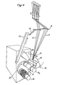
- the winder 17 has on its front face a barrel 29 carrying two pins B 1 and B 2 which are placed alternately in front of the embedding device 26.
- the various driving members necessary for the operation of the spindles and the embedding device are protected by the cover 30.
- FIG. 3 represents an embodiment of the wire guide 23.
- the latter is formed from a flat plate 31 cut so as to have an opening 32 opening towards an internal guide zone, in the shape of a V, symmetrical with respect to in the median plane passing through the xy axis.
- This internal zone has on the sides two series of V-shaped notches 33, distributed symmetrically with respect to the median plane passing through the x-y axis. The bottom of said notches is inclined relative to the vertical.
- the part 31 is fixed by suitable means, such as rivets 34, to a connecting part 35.
- This part 35 doubly bent at a right angle, has perforations 36 to lighten it. It is connected in a manner known per se to the mechanism of the crossing device 26.
- the wire guides according to the invention have as a common point be provided with notches on at least one of the sides of said zone, the bottoms 1 of the notches arranged on the same side being located at different distances from the median plane passing through the xy axis.
- each thread 15 is placed at the bottom of a notch and guided positively during the entire winding operation.
- the wires 15 are thus maintained because they pass beforehand through the combs 16 arranged on either side of the zone situated between the two planes passing through the limit switches of the wire guide 23, perpendicular to the axis of rotation of the spindle B 1 .
- the stops fixed on the embedding device 26 are adjusted in such a way that the end wires 15a, 15b and their symmetrical ones touch each of said stops in turn.
- the different threads 15 are deposited separately on the winding 28 throughout the duration of the winding, including at the ends of the winding. .
- the device according to the invention can be used with a winder having only one spindle. It is more advantageously used with a barrel winder equipped with at least two pins B 1 and B 2 and means allowing the automatic transfer of the wires from pin B 1 to pin B2.
- the spindle B 2 When the winding 28 has reached a given weight after a predetermined winding time, the spindle B 2 , provided with a support or cuff 37, is rotated and the combs 16 are moved to their high position under the action of the jack 25. Simultaneously, the arm 38 supporting the embedding device 26 pivots while moving the latter away from the spindle B 1 , and the telescopic arm 39, provided at its end with a device 40 intended to gather the son 15, brings them together and moves them to the end of the spindle B 1 on which they are wound.
- the barrel 29 pivots placing the pin B 2 in the working position and the pin B 1 in the rest position.
- the wires 15, still spaced apart by the arm 39 and the device 40, are then wound on the end of the pin B 2 .
- the transfer of the wires from pin B 1 to pin B 2 can be ensured by various means not shown, in particular by those described in patent FR-A-2 425 399.
- the arm 39 returns to its initial position and, simultaneously, the embedding device 26 is brought close to the spindle B 2 in rotation, the wires being automatically introduced into the wire guide 23.
- the combs 16 are brought back to their position low under the action of the jack 25, and each wire 15 then finds its place in one of the notches 33 of the wire guide 23.
- the device and the method according to the invention make it possible to produce windings whose weight can reach thirty kilograms and for which the separation rate of the wires is practically equal to 100%.
- the lateral flanks of the windings obtained are straight and the extraction of the wires takes place without difficulty.
- the present description relates to the winding of glass strands, but it is obvious that the invention applies to the winding of all continuous strands obtained from a thermoplastic material, since at least two strands must be kept separate. during their winding on the same support.
Landscapes
- Preliminary Treatment Of Fibers (AREA)
- Spinning Methods And Devices For Manufacturing Artificial Fibers (AREA)
- Nonwoven Fabrics (AREA)
- Adornments (AREA)
- Spinning Or Twisting Of Yarns (AREA)
- Compounds Of Unknown Constitution (AREA)
- Medicines Containing Material From Animals Or Micro-Organisms (AREA)
- Manufacture Of Motors, Generators (AREA)
- Moulding By Coating Moulds (AREA)
- Combined Means For Separation Of Solids (AREA)
- Pens And Brushes (AREA)
- Guides For Winding Or Rewinding, Or Guides For Filamentary Materials (AREA)
- Perforating, Stamping-Out Or Severing By Means Other Than Cutting (AREA)
- Crushing And Grinding (AREA)
- Saccharide Compounds (AREA)
- Winding Filamentary Materials (AREA)
- Shaping Of Tube Ends By Bending Or Straightening (AREA)
- Making Paper Articles (AREA)
- Sanitary Thin Papers (AREA)
Priority Applications (1)
| Application Number | Priority Date | Filing Date | Title |
|---|---|---|---|
| AT86401647T ATE43325T1 (de) | 1985-07-25 | 1986-07-23 | Vorrichtung und verfahren zum gleichzeitigen aufspulen mehrfacher einzelfaeden auf einen rotierenden traeger. |
Applications Claiming Priority (2)
| Application Number | Priority Date | Filing Date | Title |
|---|---|---|---|
| FR8511378A FR2585375B1 (fr) | 1985-07-25 | 1985-07-25 | Dispositif et procede pour bobiner simultanement plusieurs fils separes sur un support en rotation |
| FR8511378 | 1985-07-25 |
Publications (2)
| Publication Number | Publication Date |
|---|---|
| EP0211748A1 true EP0211748A1 (de) | 1987-02-25 |
| EP0211748B1 EP0211748B1 (de) | 1989-05-24 |
Family
ID=9321639
Family Applications (1)
| Application Number | Title | Priority Date | Filing Date |
|---|---|---|---|
| EP86401647A Expired EP0211748B1 (de) | 1985-07-25 | 1986-07-23 | Vorrichtung und Verfahren zum gleichzeitigen Aufspulen mehrfacher Einzelfäden auf einen rotierenden Träger |
Country Status (14)
| Country | Link |
|---|---|
| US (1) | US4693429A (de) |
| EP (1) | EP0211748B1 (de) |
| JP (1) | JPS6270176A (de) |
| AT (1) | ATE43325T1 (de) |
| AU (1) | AU583632B2 (de) |
| BR (1) | BR8603448A (de) |
| CA (1) | CA1307668C (de) |
| DE (1) | DE3663511D1 (de) |
| DK (1) | DK162437C (de) |
| ES (1) | ES2000547A6 (de) |
| FI (1) | FI81388C (de) |
| FR (1) | FR2585375B1 (de) |
| NO (1) | NO160707C (de) |
| ZA (1) | ZA864505B (de) |
Cited By (6)
| Publication number | Priority date | Publication date | Assignee | Title |
|---|---|---|---|---|
| EP0299506A1 (de) * | 1987-07-17 | 1989-01-18 | NITTO GLASS FIBER mfg. Co., Ltd. | Verarbeitungsmethode für Glasfäden |
| EP0367253A1 (de) * | 1988-11-04 | 1990-05-09 | Maschinenfabrik Rieter Ag | Wechselsystem für eine Fadenpositionierung bei Spulern |
| WO1991017109A1 (en) * | 1990-05-04 | 1991-11-14 | Owens-Corning Fiberglas Corporation | Reciprocating strand guide |
| FR2899571A1 (fr) * | 2006-04-10 | 2007-10-12 | Saint Gobain Vetrotex | Procede de fabrication d'un enroulement a fils separes |
| US8137094B2 (en) | 2000-10-11 | 2012-03-20 | Ocv Intellectual Capital, Llc | Method and device for producing a composite yarn |
| US8470218B2 (en) | 2006-03-30 | 2013-06-25 | Ocv Intellectual Capital, Llc | Process and device for manufacturing a composite strand |
Families Citing this family (15)
| Publication number | Priority date | Publication date | Assignee | Title |
|---|---|---|---|---|
| US4973006A (en) * | 1990-01-22 | 1990-11-27 | James Billy R | Trap guide process for high speed spinning |
| DE9101211U1 (de) * | 1991-02-02 | 1991-04-25 | Neumag - Neumuenstersche Maschinen- Und Anlagenbau Gmbh, 2350 Neumuenster, De | |
| US5256230A (en) * | 1991-07-03 | 1993-10-26 | Phillips Petroleum Company | Winding of resin impregnated fibers using a heated guide |
| US5524841A (en) * | 1994-05-26 | 1996-06-11 | Ppg Industries, Inc. | Apparatus and methods for winding a plurality of strands |
| US5665293A (en) * | 1996-03-08 | 1997-09-09 | Basf Corporation | Method of making spun yarn packages multiple individually separable yarn ends |
| US6015113A (en) * | 1997-10-06 | 2000-01-18 | E. I. Du Pont De Nemours And Company | Winder for synthetic filaments |
| US6656104B1 (en) * | 1999-11-22 | 2003-12-02 | Mark Forrester | Method and apparatus for winding spooled materials |
| US7017244B2 (en) * | 2002-06-03 | 2006-03-28 | Hunter Douglas Inc. | Beam winding apparatus |
| JP4176428B2 (ja) * | 2002-09-17 | 2008-11-05 | Tstm株式会社 | 綾振り装置 |
| US7485187B2 (en) * | 2003-07-18 | 2009-02-03 | Illinois Tool Works Inc. | Strand orientation alignment in strand coating systems and methods |
| US7172398B2 (en) * | 2003-11-17 | 2007-02-06 | Aktiengesellschaft Adolph Saurer | Stabilized filament drawing device for a meltspinning apparatus and meltspinning apparatus including such stabilized filament drawing devices |
| JP5902635B2 (ja) * | 2013-02-08 | 2016-04-13 | 村田機械株式会社 | チャック装置及びフープ巻き装置 |
| CN104088027B (zh) * | 2014-04-22 | 2017-04-05 | 郑州中远氨纶工程技术有限公司 | 合成纤维收卷装置、纺丝位及其在氨纶纤维生产中的用途 |
| CN104299724A (zh) * | 2014-09-26 | 2015-01-21 | 安徽蛟龙科技有限公司 | 一种镀锡铜丝镀完锡后的收线装置 |
| CN105112964B (zh) * | 2015-09-23 | 2017-07-21 | 苏州赛历新材料科技股份有限公司 | 一种滚动镀锡轮 |
Citations (3)
| Publication number | Priority date | Publication date | Assignee | Title |
|---|---|---|---|---|
| DE1199432B (de) * | 1958-12-29 | 1965-08-26 | Owens Corning Fiberglass Corp | Vorrichtung zum aufeinanderfolgenden, konti-nuierlichen Aufwickeln eines Fadens oder Faser-stranges, insbesondere aus in der Waerme auszieh-barem Material auf zwei oder mehreren umlaufenden Spulen |
| US3547361A (en) * | 1967-08-16 | 1970-12-15 | Owens Corning Fiberglass Corp | Apparatus for winding textile material |
| US4389024A (en) * | 1981-11-10 | 1983-06-21 | Owens-Corning Fiberglas Corporation | Method and apparatus for packaging strands |
Family Cites Families (16)
| Publication number | Priority date | Publication date | Assignee | Title |
|---|---|---|---|---|
| NL262823A (de) * | 1960-04-04 | |||
| US3371877A (en) * | 1965-05-14 | 1968-03-05 | Owens Corning Fiberglass Corp | Method for packaging multistrand roving |
| US3414956A (en) * | 1966-02-25 | 1968-12-10 | Johns Manville | Method and apparatus for winding plural strands |
| US3777470A (en) * | 1968-11-19 | 1973-12-11 | Asahi Chemical Ind | Method of forming a yarn package |
| US3653860A (en) * | 1970-05-25 | 1972-04-04 | Owens Corning Fiberglass Corp | Apparatus for processing a plurality of strand-like materials |
| US3901455A (en) * | 1971-08-13 | 1975-08-26 | Malcolm Norman Carlisle | Winding fibres |
| FR2182381A5 (de) * | 1972-04-28 | 1973-12-07 | Saint Gobain Pont A Mousson | |
| US4167252A (en) * | 1976-09-20 | 1979-09-11 | Owens-Corning Fiberglas Corporation | Strand collecting apparatus and method |
| US4130248A (en) * | 1977-05-20 | 1978-12-19 | Owens-Corning Fiberglas Corporation | Method and apparatus for packaging multistrand roving |
| FR2399377A1 (fr) * | 1977-08-03 | 1979-03-02 | Saint Gobain | Bobinoir, notamment pour fils de matiere thermoplastique |
| FR2425399A1 (fr) * | 1978-05-12 | 1979-12-07 | Saint Gobain | Perfectionnement au transfert d'un materiau filiforme d'une broche d'enroulement a une autre |
| US4322041A (en) * | 1979-09-26 | 1982-03-30 | Fiberglas Canada Inc. | Method of and apparatus for winding roving packages |
| US4421282A (en) * | 1981-07-27 | 1983-12-20 | Owens-Corning Fiberglas Corporation | Apparatus for forming and packaging multistrand roving |
| US4488686A (en) * | 1983-01-10 | 1984-12-18 | Ppg Industries, Inc. | Apparatus and method for packaging a plurality of filaments or bundles of filaments |
| US4509702A (en) * | 1983-01-27 | 1985-04-09 | Ppg Industries, Inc. | Apparatus for packaging a plurality of fibers or strands |
| US4538773A (en) * | 1984-02-21 | 1985-09-03 | Ppg Industries, Inc. | Apparatus for collecting strands |
-
1985
- 1985-07-25 FR FR8511378A patent/FR2585375B1/fr not_active Expired
- 1985-11-14 US US06/798,071 patent/US4693429A/en not_active Expired - Fee Related
-
1986
- 1986-06-17 ZA ZA864505A patent/ZA864505B/xx unknown
- 1986-06-19 DK DK288286A patent/DK162437C/da not_active IP Right Cessation
- 1986-06-24 AU AU59185/86A patent/AU583632B2/en not_active Ceased
- 1986-07-10 NO NO862794A patent/NO160707C/no unknown
- 1986-07-22 JP JP61172666A patent/JPS6270176A/ja active Pending
- 1986-07-22 BR BR8603448A patent/BR8603448A/pt not_active IP Right Cessation
- 1986-07-23 EP EP86401647A patent/EP0211748B1/de not_active Expired
- 1986-07-23 DE DE8686401647T patent/DE3663511D1/de not_active Expired
- 1986-07-23 ES ES8600504A patent/ES2000547A6/es not_active Expired
- 1986-07-23 AT AT86401647T patent/ATE43325T1/de not_active IP Right Cessation
- 1986-07-24 FI FI863038A patent/FI81388C/fi not_active IP Right Cessation
- 1986-07-25 CA CA000514718A patent/CA1307668C/fr not_active Expired - Fee Related
Patent Citations (3)
| Publication number | Priority date | Publication date | Assignee | Title |
|---|---|---|---|---|
| DE1199432B (de) * | 1958-12-29 | 1965-08-26 | Owens Corning Fiberglass Corp | Vorrichtung zum aufeinanderfolgenden, konti-nuierlichen Aufwickeln eines Fadens oder Faser-stranges, insbesondere aus in der Waerme auszieh-barem Material auf zwei oder mehreren umlaufenden Spulen |
| US3547361A (en) * | 1967-08-16 | 1970-12-15 | Owens Corning Fiberglass Corp | Apparatus for winding textile material |
| US4389024A (en) * | 1981-11-10 | 1983-06-21 | Owens-Corning Fiberglas Corporation | Method and apparatus for packaging strands |
Cited By (10)
| Publication number | Priority date | Publication date | Assignee | Title |
|---|---|---|---|---|
| EP0299506A1 (de) * | 1987-07-17 | 1989-01-18 | NITTO GLASS FIBER mfg. Co., Ltd. | Verarbeitungsmethode für Glasfäden |
| EP0367253A1 (de) * | 1988-11-04 | 1990-05-09 | Maschinenfabrik Rieter Ag | Wechselsystem für eine Fadenpositionierung bei Spulern |
| US4969607A (en) * | 1988-11-04 | 1990-11-13 | Rieter Machine Works Ltd. | Apparatus for introducing a yarn into the catch slot of an empty bobbin tube |
| WO1991017109A1 (en) * | 1990-05-04 | 1991-11-14 | Owens-Corning Fiberglas Corporation | Reciprocating strand guide |
| US8137094B2 (en) | 2000-10-11 | 2012-03-20 | Ocv Intellectual Capital, Llc | Method and device for producing a composite yarn |
| US8470218B2 (en) | 2006-03-30 | 2013-06-25 | Ocv Intellectual Capital, Llc | Process and device for manufacturing a composite strand |
| FR2899571A1 (fr) * | 2006-04-10 | 2007-10-12 | Saint Gobain Vetrotex | Procede de fabrication d'un enroulement a fils separes |
| WO2007116181A1 (fr) * | 2006-04-10 | 2007-10-18 | Ocv Intellectual Capital, Llc | Procédé de fabrication d'un enroulement a fils séparés |
| CN101448724B (zh) * | 2006-04-10 | 2013-01-23 | Ocv智识资本有限责任公司 | 用于制造具有分离的丝线的绕组的方法 |
| US8882019B2 (en) | 2006-04-10 | 2014-11-11 | Ocv Intellectual Capital, Llc | Method for the manufacture of a wound package with separate strands |
Also Published As
| Publication number | Publication date |
|---|---|
| ES2000547A6 (es) | 1988-03-01 |
| FR2585375B1 (fr) | 1988-04-08 |
| ATE43325T1 (de) | 1989-06-15 |
| FI81388B (fi) | 1990-06-29 |
| ZA864505B (en) | 1987-02-25 |
| NO160707C (no) | 1989-05-24 |
| DK162437B (da) | 1991-10-28 |
| DK288286A (da) | 1987-01-26 |
| DK162437C (da) | 1992-03-23 |
| EP0211748B1 (de) | 1989-05-24 |
| FR2585375A1 (fr) | 1987-01-30 |
| AU5918586A (en) | 1987-01-29 |
| FI863038A0 (fi) | 1986-07-24 |
| FI863038A (fi) | 1987-01-26 |
| DK288286D0 (da) | 1986-06-19 |
| BR8603448A (pt) | 1987-03-04 |
| JPS6270176A (ja) | 1987-03-31 |
| NO862794D0 (no) | 1986-07-10 |
| NO862794L (no) | 1987-01-26 |
| AU583632B2 (en) | 1989-05-04 |
| CA1307668C (fr) | 1992-09-22 |
| FI81388C (fi) | 1990-10-10 |
| NO160707B (no) | 1989-02-13 |
| DE3663511D1 (en) | 1989-06-29 |
| US4693429A (en) | 1987-09-15 |
Similar Documents
| Publication | Publication Date | Title |
|---|---|---|
| EP0211748B1 (de) | Vorrichtung und Verfahren zum gleichzeitigen Aufspulen mehrfacher Einzelfäden auf einen rotierenden Träger | |
| EP0040145A1 (de) | Vorrichtung zum Schneiden langer Fasern, insbesondere von Glasfasern | |
| CA2071445C (fr) | Procede de fabrication d'un pneumatique et machines pour la mise en oeuvre de ce procede | |
| EP0005664A1 (de) | Verfahren zum Führen eines faserförmigen Materials von einer Aufwickelspindel zur anderen sowie Vorrichtung zur Durchführung des Verfahrens | |
| EP0022421A1 (de) | Verfahren und Vorrichtung zum Herstellen eines Zwirnes mit über seine Länge abwechselnder S- und Z-Drehung | |
| EP0101351B1 (de) | Verfahren und Vorrichtung zum Herstellen von komplexen Gewebe durch multidirektionales Weben | |
| FR2879580A1 (fr) | Appareil dans une machine de preparation de filature,par exemple une carde, un mecanisme d'etirage de carde,un cadre d'etirage, une peigneuse ou equivalent, destine a changer des pots a ruban | |
| CH631941A5 (fr) | Procede et dispositif de lancement de fils pour leur renvidage. | |
| EP0098762A1 (de) | Dreidimensional gewebte hohle Armierung, Verfahren und Vorrichtung zur Herstellung dieser Armierung | |
| CA1267875A (fr) | Procede et dispositif de lancement simultane de plusieurs fils textiles delivres en continu | |
| EP1369222A1 (de) | Verfahren zum selektiven Einbringen von Fäden in textilen multidimensionalen Vorformlingen und Vorrichtung zur Durchführung des Verfahrens | |
| FR2480802A1 (fr) | Dispositif de broche a double torsion | |
| FR2907798A1 (fr) | Procede de traitement de fils par tricotage-detricotage | |
| EP1611043B1 (de) | Vorrichtung zum anbringen und abnehmen von hülsen für fäden in einer textilmaschine | |
| EP2060666B1 (de) | Speichervorrichtung für Garne | |
| CA2377262A1 (fr) | Procede de fabrication d'enroulements tronconiques de fil | |
| EP2963171B1 (de) | Herstellungsverfahren eines textilgitters, und anlage und entsprechende materialien | |
| FR2475513A1 (fr) | Dispositif d'alimentation en fil | |
| CH620654A5 (de) | ||
| CH307597A (fr) | Procédé de tissage et métier rectiligne pour sa mise en oeuvre. | |
| EP1112954B1 (de) | Vorrichtung und Verfahren zum Knoten, Etikettieren und Palettieren von Spulen am Ende einer Maschine zur Spulenherstellung | |
| FR2789409A1 (fr) | Machine de retordage de fils, verre notamment | |
| BE1003829A6 (fr) | Procede et dispositif de fabrication d'un tapis a points noues. | |
| FR2743821A1 (fr) | Reseau maille a base de fils non tisses, procede et installation pour son obtention | |
| FR2518595A1 (fr) | Dispositif pour la realisation d'une nappe constituee de fils paralleles et d'articles complexes divers comportant une telle nappe |
Legal Events
| Date | Code | Title | Description |
|---|---|---|---|
| PUAI | Public reference made under article 153(3) epc to a published international application that has entered the european phase |
Free format text: ORIGINAL CODE: 0009012 |
|
| AK | Designated contracting states |
Kind code of ref document: A1 Designated state(s): AT BE CH DE FR GB IT LI LU NL SE |
|
| 17P | Request for examination filed |
Effective date: 19870807 |
|
| 17Q | First examination report despatched |
Effective date: 19880414 |
|
| GRAA | (expected) grant |
Free format text: ORIGINAL CODE: 0009210 |
|
| AK | Designated contracting states |
Kind code of ref document: B1 Designated state(s): AT BE CH DE FR GB IT LI LU NL SE |
|
| REF | Corresponds to: |
Ref document number: 43325 Country of ref document: AT Date of ref document: 19890615 Kind code of ref document: T |
|
| REF | Corresponds to: |
Ref document number: 3663511 Country of ref document: DE Date of ref document: 19890629 |
|
| ITF | It: translation for a ep patent filed |
Owner name: DR. ING. A. RACHELI & C. |
|
| GBT | Gb: translation of ep patent filed (gb section 77(6)(a)/1977) | ||
| PLBE | No opposition filed within time limit |
Free format text: ORIGINAL CODE: 0009261 |
|
| STAA | Information on the status of an ep patent application or granted ep patent |
Free format text: STATUS: NO OPPOSITION FILED WITHIN TIME LIMIT |
|
| 26N | No opposition filed | ||
| ITTA | It: last paid annual fee | ||
| PGFP | Annual fee paid to national office [announced via postgrant information from national office to epo] |
Ref country code: CH Payment date: 19920730 Year of fee payment: 7 |
|
| PGFP | Annual fee paid to national office [announced via postgrant information from national office to epo] |
Ref country code: NL Payment date: 19920731 Year of fee payment: 7 |
|
| PGFP | Annual fee paid to national office [announced via postgrant information from national office to epo] |
Ref country code: DE Payment date: 19920914 Year of fee payment: 7 |
|
| PGFP | Annual fee paid to national office [announced via postgrant information from national office to epo] |
Ref country code: GB Payment date: 19930618 Year of fee payment: 8 |
|
| PGFP | Annual fee paid to national office [announced via postgrant information from national office to epo] |
Ref country code: AT Payment date: 19930625 Year of fee payment: 8 |
|
| PGFP | Annual fee paid to national office [announced via postgrant information from national office to epo] |
Ref country code: SE Payment date: 19930719 Year of fee payment: 8 |
|
| PGFP | Annual fee paid to national office [announced via postgrant information from national office to epo] |
Ref country code: FR Payment date: 19930722 Year of fee payment: 8 |
|
| PGFP | Annual fee paid to national office [announced via postgrant information from national office to epo] |
Ref country code: BE Payment date: 19930726 Year of fee payment: 8 |
|
| PGFP | Annual fee paid to national office [announced via postgrant information from national office to epo] |
Ref country code: LU Payment date: 19930729 Year of fee payment: 8 |
|
| PG25 | Lapsed in a contracting state [announced via postgrant information from national office to epo] |
Ref country code: LI Effective date: 19930731 Ref country code: CH Effective date: 19930731 |
|
| EPTA | Lu: last paid annual fee | ||
| PG25 | Lapsed in a contracting state [announced via postgrant information from national office to epo] |
Ref country code: NL Effective date: 19940201 |
|
| NLV4 | Nl: lapsed or anulled due to non-payment of the annual fee | ||
| REG | Reference to a national code |
Ref country code: CH Ref legal event code: PL |
|
| PG25 | Lapsed in a contracting state [announced via postgrant information from national office to epo] |
Ref country code: DE Effective date: 19940401 |
|
| PG25 | Lapsed in a contracting state [announced via postgrant information from national office to epo] |
Ref country code: LU Free format text: LAPSE BECAUSE OF NON-PAYMENT OF DUE FEES Effective date: 19940723 Ref country code: GB Effective date: 19940723 Ref country code: AT Effective date: 19940723 |
|
| PG25 | Lapsed in a contracting state [announced via postgrant information from national office to epo] |
Ref country code: SE Effective date: 19940724 |
|
| PG25 | Lapsed in a contracting state [announced via postgrant information from national office to epo] |
Ref country code: BE Effective date: 19940731 |
|
| BERE | Be: lapsed |
Owner name: VETROTEX SAINT-GOBAIN Effective date: 19940731 |
|
| EUG | Se: european patent has lapsed |
Ref document number: 86401647.2 Effective date: 19950210 |
|
| GBPC | Gb: european patent ceased through non-payment of renewal fee |
Effective date: 19940723 |
|
| PG25 | Lapsed in a contracting state [announced via postgrant information from national office to epo] |
Ref country code: FR Effective date: 19950331 |
|
| EUG | Se: european patent has lapsed |
Ref document number: 86401647.2 |
|
| REG | Reference to a national code |
Ref country code: FR Ref legal event code: ST |
|
| PG25 | Lapsed in a contracting state [announced via postgrant information from national office to epo] |
Ref country code: IT Free format text: LAPSE BECAUSE OF NON-PAYMENT OF DUE FEES;WARNING: LAPSES OF ITALIAN PATENTS WITH EFFECTIVE DATE BEFORE 2007 MAY HAVE OCCURRED AT ANY TIME BEFORE 2007. THE CORRECT EFFECTIVE DATE MAY BE DIFFERENT FROM THE ONE RECORDED. Effective date: 20050723 |