EP0208516A2 - Verfahren und Vorrichtung zur Bestimmung von Oberflächenprofilen - Google Patents
Verfahren und Vorrichtung zur Bestimmung von Oberflächenprofilen Download PDFInfo
- Publication number
- EP0208516A2 EP0208516A2 EP86305179A EP86305179A EP0208516A2 EP 0208516 A2 EP0208516 A2 EP 0208516A2 EP 86305179 A EP86305179 A EP 86305179A EP 86305179 A EP86305179 A EP 86305179A EP 0208516 A2 EP0208516 A2 EP 0208516A2
- Authority
- EP
- European Patent Office
- Prior art keywords
- specimen
- wafer
- line
- focus
- imaging system
- Prior art date
- Legal status (The legal status is an assumption and is not a legal conclusion. Google has not performed a legal analysis and makes no representation as to the accuracy of the status listed.)
- Withdrawn
Links
Images


Classifications
-
- G—PHYSICS
- G01—MEASURING; TESTING
- G01N—INVESTIGATING OR ANALYSING MATERIALS BY DETERMINING THEIR CHEMICAL OR PHYSICAL PROPERTIES
- G01N21/00—Investigating or analysing materials by the use of optical means, i.e. using sub-millimetre waves, infrared, visible or ultraviolet light
- G01N21/84—Systems specially adapted for particular applications
- G01N21/88—Investigating the presence of flaws or contamination
- G01N21/95—Investigating the presence of flaws or contamination characterised by the material or shape of the object to be examined
- G01N21/956—Inspecting patterns on the surface of objects
-
- G—PHYSICS
- G01—MEASURING; TESTING
- G01B—MEASURING LENGTH, THICKNESS OR SIMILAR LINEAR DIMENSIONS; MEASURING ANGLES; MEASURING AREAS; MEASURING IRREGULARITIES OF SURFACES OR CONTOURS
- G01B11/00—Measuring arrangements characterised by the use of optical techniques
- G01B11/02—Measuring arrangements characterised by the use of optical techniques for measuring length, width or thickness
-
- G—PHYSICS
- G01—MEASURING; TESTING
- G01B—MEASURING LENGTH, THICKNESS OR SIMILAR LINEAR DIMENSIONS; MEASURING ANGLES; MEASURING AREAS; MEASURING IRREGULARITIES OF SURFACES OR CONTOURS
- G01B11/00—Measuring arrangements characterised by the use of optical techniques
- G01B11/24—Measuring arrangements characterised by the use of optical techniques for measuring contours or curvatures
-
- G—PHYSICS
- G02—OPTICS
- G02B—OPTICAL ELEMENTS, SYSTEMS OR APPARATUS
- G02B21/00—Microscopes
- G02B21/0004—Microscopes specially adapted for specific applications
- G02B21/002—Scanning microscopes
- G02B21/0024—Confocal scanning microscopes (CSOMs) or confocal "macroscopes"; Accessories which are not restricted to use with CSOMs, e.g. sample holders
- G02B21/0052—Optical details of the image generation
- G02B21/006—Optical details of the image generation focusing arrangements; selection of the plane to be imaged
-
- G—PHYSICS
- G01—MEASURING; TESTING
- G01N—INVESTIGATING OR ANALYSING MATERIALS BY DETERMINING THEIR CHEMICAL OR PHYSICAL PROPERTIES
- G01N21/00—Investigating or analysing materials by the use of optical means, i.e. using sub-millimetre waves, infrared, visible or ultraviolet light
- G01N21/84—Systems specially adapted for particular applications
- G01N21/88—Investigating the presence of flaws or contamination
- G01N21/95—Investigating the presence of flaws or contamination characterised by the material or shape of the object to be examined
- G01N21/9501—Semiconductor wafers
-
- G—PHYSICS
- G01—MEASURING; TESTING
- G01N—INVESTIGATING OR ANALYSING MATERIALS BY DETERMINING THEIR CHEMICAL OR PHYSICAL PROPERTIES
- G01N2201/00—Features of devices classified in G01N21/00
- G01N2201/10—Scanning
- G01N2201/103—Scanning by mechanical motion of stage
Definitions
- the present invention pertains to systems for scanning surface patterns on specimens such as semiconductor wafers or the like, and more particularly, it pertains to methods and apparatus for accurately obtaining a cross-sectional surface profile of such specimens.
- the inspection of semiconductor wafers typically provides a means whereby certain processing defects can be detected or whereby linewidth measurements can be made so as to determine whether or not the manufacturing process has been performed correctly. Since the tolerance limits for the dimensions which must be detected and measured accurately are in the micron or even submicron range, microscope imaging systems generally require a high degree of imaging resolution.
- the present invention methods and apparatus are provided for systematically obtaining the cross-sectional profile within a given area on the semiconductor wafer surface.
- the information provided by this profile can thereafter be effectively utilized to make the conventional pattern linewidth measurements with a generally greater degree of accuracy than that provided by the systems of the prior art.
- the profile provides the necessary information to determine at what specific levels the given wafer area should be scanned such that the entire area of the wafer can be rapidly scanned only at such selected levels to provide all of the relevant information necessary, reducing the processing times and digital storage capacities required.
- an optical imaging system is provided to both project a sharply defined beam onto a small spot upon the wafer surface and to detect the image of the reflected spot with respect to a measurable characteristic of the reflected beam indicative of the reflective surface at or near the focal plane.
- the optical imaging system and the wafer are relatively moved in a plane generally parallel to the surface of the wafer so that the projected spot scans a line across a portion or given area of the wafer, and means are provided for recording and storing a signal representative of the measurable characteristic at a plurality of very closely spaced positions along the scan line.
- the focus level of the imaging system is successively changed by moving the wafer and imaging system closer together or further apart after each pass along a scan line until a plurality of scans have been made completely passing through the relevant surface detail of the wafer. Then, for each single recording position along the scan line, that focus level of the system is determined wherein a signal most characteristic of a surface indication (e.g., a maximum relected intensity signal) was obtained.
- a signal most characteristic of a surface indication e.g., a maximum relected intensity signal
- This surface profile information can then be utilized for directly making a pattern linewidth measurement, or the information can be used for selecting the particular surface levels at which the optical system needs to be automatically focused during subsequent scans throughout the particular portion or area of the wafer. This permits the selected wafer area to be thoroughly scanned and three-dimensional images to be produced.
- an optics module 30 is provided to focus a sharply defined beam from a laser source 40 on a small spot upon an underlying semiconductor wafer, w.
- the optics module comprises a confocal optical imaging system which is controlled by and provides data information signals to a computer system 22.
- the computer outputs information to various display units including an image display monitor 24a (where the "superfocus" image of the entire scanned area is displayed) and a graphics video display unit 24b (where the profiles, graphs and histograms are displayed).
- the surface of the semiconductor wafer, w, to be inspected by the system underlies the optical imaging system and extends in a plane generally perpendicular to the projected beam.
- the wafer is arranged to be moved in this plane in x and y orthogonal directions by x and y stages 34, 32, respectively and also by a vibratory scanning mechanism 46 aligned for movement in the x direction.
- the x and y stages are driven by conventional motor control circuitry 36.
- Movement in the z direction i.e., in a direction generally parallel to the light beam projected from laser source 40, is accomplished by a focus control mechanism 28 which shifts an objective lens 26 (the last element of the optical system) over very small vertical distances in order to change the focal plane of the optical system.
- the focus control mechanism is operated from the computer system through a focus control signal from conventional control circuitry 38 to shift the lens 26 up or down.
- the beam from laser source 40 is sharply focused with a very narrow depth of field, and it is adapted to be reflected from a surface on wafer w (if one is present) at the focal plane back through the optical system to a photodetector 42.
- the signal from the photodetector is sampled and digitized by the control circuitry 44 and transmitted to the computer system 22 and represents the intensity of the reflected light received from the projected spot on the surface of wafer w.
- These digital signals are provided as a function of the focus level. z, and also as a function of separate, closely spaced positions in the x-y plane. Since the optical system has a very narrow depth of field, reflected intensity peaks as the focal plane coincides with an underlying reflective surface and drops off rather sharply as the wafer surface is moved away from the focal plane. Thus the height of the wafer at any particular planar (x,y) position thereon can be readily detected by operating the focus control mechanism 28 to achieve a maximum output signal representing the intensity of the reflected light.
- the computer system 22 tracks both the x, y positions of the wafer with respect to the beam and the z level focal plane location of the beam and coordinates this information with the intensity signals from photodetector 42 in order to provide a three dimensional output representation of the portion of the wafer that is scanned.
- the wafer, w is moved in the horizontal plane by x and y stages 34 and 32, respectively, which are controlled by x, y stage motor control circuitry 36 under the monitoring of the computer system 22.
- the stages 32, 34 comprise conventional precision translation tables provided with optical position encoders for submicron resolution and accuracy.
- the motor control circuitry 36 is also conventional in nature providing drive signals for moving the stages and including A/D circuitry for receiving and processing the signals from the position encoders so as to accurately monitor the position of the wafer at any given instant.
- the z-axis focus control circuitry 38 provides an output voltage for the focus control mechanism 28 which, in the present instance, comprises a piezoelectric crystal that expands or contracts in the vertical plane and responds to the applied voltage to shift the relative vertical position of objective lens 26.
- the control circuitry 44 for the entire system is adapted to receive a continuous input light intensity signal from the photodetector 42 through amplifier 45 and synchronize this data with the scanner 46 position information.
- the control circuitry 44 also serves to output a scan drive signal (a sinosoidal wave form) to the vibratory scanning mechanism 46 through an amplifier 47.
- the scanning mechanism 46 vibrates the wafer rapidly in the x direction.
- the stage, or linear translator, 32 may be adapted to simultaneously move the wafer w slowly in the direction during the vibratory scanning movement in the x direction when it is desired to provide a two dimensional planar scan at a particular level on the wafer. By scanning at a plurality of levels, a three dimensional scan is obtained,
- the basic profiling technique of the present invention requires that the scanner 46 move only in the x direction making a repeated number of scans over the same line on the wafer while incrementally changing the level of lens 26 through focus control mechanism 28 after each individual scan.
- control circuitry 44_it will be seen that the scan drive voltage is provided digitally out of the line scan wave form memory circuitry 48 and that a D/A converter 49 converts the digital signals to an analog signal for appropriate amplification by the amplifier 47.
- the memory 48 is addressed.by scan control and synchronization circuitry 50.
- the incoming analog signal from the photodetector 42 is converted to a digital signal by A/D converter 51.
- a line scan distortion memory 52 is provided to control the timing between the samples.
- the timing information from memory 52 is utilized by pixel timing and synchronizing circuitry 53 which controls a line scan pixel memory 54 that accepts and stores the digital input signals at the appropriate times.
- Each sampled signal corresponds to a pixel which is a representation of a very small incremental area on the wafer with the sampled signal at the time being a measurement of the reflected light from such incremental area.
- FIG. 2 The mechanical structure which comprises the semiconductor wafer scanning system is shown in Figures 2 through 5.
- the entire wafer drive apparatus and optical system is arranged to be mounted upon a large surface plate 60 which is seated upon a table 61 and isolated therefrom by four piston and cylinder type air springs 62 located so as to support each corner of the surface plate.
- a general frame structure 64 is elevated above the surface plate 60 to provide support for the optics module 20 including the vertically shiftable focus control mechanism 28.
- the details of the focus control mechanism are best shown in Figures 2, 4, and 5.
- the movable objective lens 26 will be seen to be mounted within a cage 72 open at the top and the front and with a back face (Figure 5) adapted to slide within track 73 on the upright face of the frame structure 64.
- a support bracket 70 is attached to one side of cage 72 projecting outwardly therefrom to support a DC servo motor 66 with a projecting lead screw 67 thereof being adapted to engage the upper face of a support bracket 68 secured to a main upright portion of frame 64. It will be seen (from Figure 2) that movement of the screw 67 within the motor assembly 66 serves to raise or lower the objective lens 26 relative to the underlying wafer support assembly.
- This lens movement is provided only for gross alignment of the optical system relative to the wafer surface, i.e., to move the optical system so that the surface of wafer w lies in the basic focal range of the optics. As will be . explained presently, this gross movement will initially place the focal plane of the optical system close to but above the top surface of the wafer so that the lens 26 can thereafter be successively moved closer to the wafer as the beam from laser 40 is scanned across the wafer.
- Use of the motor 66 to elevate lens 26 well above the underlying wafer support structure also permits the wafer w to be readily loaded and unloaded.
- the fine focusing (i.e., fine vertical adjustment) of the objective lens 26 is accomplished by means of a piezoelectric crystal 76 of generally cylindrical shape (Figs. 4 and 5) which is attached between the base of the cage 72 and an overhead annular support member 74 which has a central hub 75 to which the upper end of the mount for lens 26 is threaded (Fig. 4).
- a piezoelectric crystal 76 of generally cylindrical shape (Figs. 4 and 5) which is attached between the base of the cage 72 and an overhead annular support member 74 which has a central hub 75 to which the upper end of the mount for lens 26 is threaded (Fig. 4).
- the crystal 76 may be axially contracted or expanded in the direction of the arrows (Fig. 4) so as to, in turn, lower or elevate the objective lens 26 relative to the underlying wafer.
- lens 26 during the application of different electrical potentials to crystal 76 will be in the submicron range (e.g., 0.01 microns per increment) so that relatively small differences in surface levels on the face of the wafer are capable of being distinguished.
- each of the x and y drive devices or stages 34, 32 is comprised of a conventional precision translation table which, in the presently described embodiment of the invention, is designed to have about six to eight inches of linear travel.
- These tables each include a drive motor 82 which serves to drive a slide block 80 within a channel shaped frame 83 by means of a lead screw (not shown) which is threaded to a nut attached to the slide block 80.
- each translation - table includes an optical position encoder therein with submicron resolution and accuracy which serves to feed continuous position signals back to the computer 22 so that the precise position of the wafer in the x-y plane at any given time can be controlled and correlated with the reflected intensity measurements from the optical system during the operation of the apparatus.
- a flat lower tilt plate 84 is attached to the upper face of the slide block 80 of the upper, or y, stage translation table 32, and a middle tilt plate 86 is secured thereto by means of a leaf spring 88 which is rigidly bolted to the adjacent spaced ends of both of the tilt plates.
- a tilt adjusting screw 87 is threaded through the end of tilt plate 86 opposite to the mounting of spring 88 so as to bear against the upper surface of the lower tilt plate 84 so that the middle tilt plate (and the structure supported there- above) can be tilted about the x-axis by adjustment of the screw 87.
- an upper tilt plate 90 is secured in spaced relationship to the middle tilt plate 86 by means of a leaf spring 92 bolted to their rearward edges, and a tilt adjusting screw 91 is threaded through the forward edge of tilt plate 90 to bear against the upper surface of tilt plate 86 so as to adjustably rotate the tilt plate 90 about the y axis.
- the vibratory scanner mechanism 46 by which the wafer w is rapidly vibrated in the direction of the x-axis, is shown in detail in Figure 3. It will be seen that the scanner mechanism comprises a rectangular structure including a pair of leaf springs 120a and 120b, for supporting for vibratory movement a drive bar 78, and a pair of tension adjusting leaf springs 121a and 121b.
- the springs are arranged in a rectangular structure by attachment to four corner blocks 122 with the ends of each of the springs being tightly bolted to the corner blocks.
- the solid drive bar 78 is firmly attached to and extends between the midpoints of each of the vibratory leaf springs 120a and 120b. Positioned atop the drive bar 78 (see Fig.
- FIG. 2 2) is a vacuum chuck 89 which is supplied with a vacuum to hold the wafer w securely upon its flat upper surface.
- the rearwardly projecting end 78a of the drive bar 78 mounts a coil 79 to which a drive current is applied from the control circuitry 44 through amplifier 47 (Fig. 1).
- a plurality of fixed magnets 101 are mounted upon spaced upright mounting blocks 100 between which the coil 79 is positioned so as to complete the electromechancial drive arrangement for the scanner.
- the mounting blocks 100 are positioned upon and secured to an extension 90a of the upper tilt plate 90, as shown in Figure 3, and also serve to mount the terminals 101a through which the coil 79 is connected to the drive circuitry.
- U-shaped mounting blocks 124 are bolted to the midpoint of each of the tensioning springs 121a, 121b through attachment plates 128.
- Each of the attachment plates has a threaded hole in the center thereof for receiving a set screw 127.
- Each screw extends freely through a passage in the associated U-shaped mounting block 124.
- Abutment blocks 125 are fixedly secured to the upper face of upper tilt plate 90 and provide surfaces against which the set screws 127 abut.
- Each mounting block 124 is also secured upon the upper face of upper tilt plate 90 by means of bolts 126 which are received in slots extending through the blocks so that loosening of the bolts permits the blocks to be shifted laterally with respect to the scanner.
- the mounting blocks 124 are thus free to slide upon the lateral faces of the abutment blocks 125 before the bolts 126 are fully tightened thereby permitting the tension springs 121a, 122b to be bowed outwardly from their innermost positions. This is done in order to apply the proper amount of tension in the leaf springs 120a and 120b so as to adjust the.mechanical resonant frequency of the system to that desired.
- This mechanical resonant frequency should be set just slightly higher than the operating or drive frequency of the system so that the system will be energy efficient but so that the oscillatory drive will never pass through the resonance point wherein loss of control and damage to the structure could occur.
- each tensioning spring 121a, 121b can be adjusted separately through its associated set screw 127, it will be recognized that the separate adjustment of each side of the spring support system can be used to compensate for any asymmetry in the spring system construction to insure that a perfectly symmetrical drive arrangement is achieved.
- the basic x-y planar drive mechanisms 34, 32 can be used to bring the wafer to a location beneath the optical imaging system 20 wherein the beam from laser 40 will overlie a particular site on the wafer.
- the basic x-y planar drive mechanisms 34, 32 can be used to bring the wafer to a location beneath the optical imaging system 20 wherein the beam from laser 40 will overlie a particular site on the wafer.
- the focus control mechanism 28 is operated to bring the focus level to a focal plane z 1 which is chosen so that it will always be above the uppermost surface level of the wafer even if the wafer may vary somewhat in thickness or not lie in a perfectly horizontal plane (see the top figure in Fig. 8).
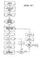
- the subroutine V(z) for obtaining and displaying a z (vertical) profile along a line (in the x direction) on the wafer is then carried out. This subroutine is shown specifically in Figures 7A, 7B, and 7C;
- Fig. 7A the data collection phase, it will be seen that the focus control mechanism 28 is initially operated (through control circuitry 38) to bring the focal level of the optical system to its uppermost scanning level z1 as explained previously.
- the vibratory scanning mechanism 46 is now operated to scan the beam from laser .40 along a line on the wafer while the control circuitry 44 (Fig. 1J samples the reflectivity data from photodetector 42 along the line at n samples (e.g., 512 samples) in a single (i.e., one-directional) scanning movement.
- n samples e.g., 512 samples
- the focus control mechanism 28 is operated to lower the focal level by an incremental distance (typically, a few hundredths of a micron). This procedure is repeated as the focal level (the z level) is successively lowered through m levels (e.g., 256 levels), as indicated in Figure 7A, it being understood that at each level, 512 samples along the x direction will be obtained and all of this information will be stored within a memory in the computer system 22.
- m levels e.g., 256 levels
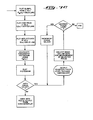
- the data will be processed in accordance with the programming shown in F i g. 7B.
- the data is saved within the computer in an array x i by zjwherein i (the spaced data taking positions along the x axis) will typically be about 512 while j (the incremental focal levels of the optical system) will typically be about 256.
- the data storage for the profiling operation must accommodate 512 by 256 or approximately 131K bytes of information.
- the system starts at z 1 and x and looks for the maximum peak value (P m ) and the reflectivity signal (R) at such peak value and also looks for the first peak value P 1 .
- the program steps through each z level (1 through.256) successively testing the reflectivity values to first locate a first peak value (i.e., where the reflected intensity first rises to a peak value and then drops off) and then to locate a maximum peak value (i.e., the highest reflected intensity value).
- the maximum peak value will occur at that z level where the basic reflecting surface on the wafer lies precisely at the focal plane below the optical system, and the first peak (if there is a peak prior to the maximum value) will occur at that z level where a transparent or semi-transparent layer overlying the underlying basic reflecting surface lies precisely at the focal plane.
- the computer will store the z level value (z j ) for the x .o position and also the reflectivity value R at the maximum peak P .
- the lower three graphs of Figure 8 show the data display which is provided on the graphics video display unit 24b in three separate arrays.
- the upper graph represents z (depth at the wafer surface as referenced to the optical system) vs. x (linear location across the scan area).
- Fig. 7B the stored data
- a solid line comprises the z-axis profile or cross-sectional profile of the wafer surface as shown in the top illustration of Figure 8.
- the reflectivity at each maximum signal position is also plotted on a separate graph (R vs.
- the underlying silicon substrate level has a relatively low reflectivity; the silicon dioxide layer has a higher reflectivity level; and the metallic aluminum layers exhibit the highest reflectivity levels.
- the wavy surface of the aluminum lines reflects the granular metallic nature of the relatively flat metallic surface which inherently has variable reflectivity levels therein.
- a histogram is calculated and plotted as indicated in Figure 7C and as shown in the lowermost graphical display in Figure 8.
- the histogram utilizes the same data used in the uppermost graph (z vs. x), but it is plotted in a different manner.
- the number of pixels i.e., x positions x I - x 512 found at each z level where a maximum reflectivity signal was observed are plotted. Comparing the upper and lower graphs of Figure 8 it will be seen that the lowermost level A has the highest number of pixels while the level of the metallic lines B has the next highest and that all of these pixels are closely centered about the A and B elevations.
- a bell-shaped curve is formed about the C level; such curve representing the photoresist material capping the aluminum layers with the peak representing the average level of such material.
- the D and E levels are the smallest and are appropriately spaced at the relatively highest focal depth levels.
- the significance of preparing and displaying such a histogram is that either operator selection or conventional computer graphical analysis techniques can be utilized to locate each of the indicated peaks (A-E) which represent the specific levels of interest for scanning on the semiconductor wafer surface.
- the automatic focusing function can be activated, wherein the z level at each clearly definable peak. in the histogram will be selected for scanning, or the user can select only such levels as desired for further scanning.
- the system will thereafter be operated so that the focus control mechanism 28 will move the optical system to focus only on such selected levels rather than scanning the entire site area at each individual z level.
- the z vs. x profile is utilized in an effective manner so that an entire site, i.e., the entire two-dimensional array of x and y positions may be scanned to obtain the three-dimensional representation but only at a few selected depth levels without losing any relevant information and while keeping the amount of stored data during one scan at a manageable level.
- the automatically selected focus levels can be set and sequentially fed to the focus control circuitry 38 (Fig. 1) prior to each complete two dimensional scan at a given z level.
- the system is ready to rapidly shift the position of the wafer relative to the optical system (by translation stages 32, 34) so that a new site or area underlies the vibratory scanning area of the optical system, and the process can be repeated.
- a nominal focus level (z nom is selected as the uppermost detectable layer on the wafer; for example, in the wafer cross-section of Figure 8, top level E would represent the nominal focus level as indicated.
- each level of interest for scanning at or below level E would be defined by a focus offset or ⁇ z j value with ⁇ z j being defined as znom minus the z level of scanning interest (e.g., level A, B, C, etc.).
- each of the other j values (j3 - j5) would be set for levels C, B and A with the offset ( ⁇ ) values being set at the corresponding z level differential with level E.
- These focus offsets ⁇ z j are thus determined and stored. Then, with j being initially set equal to one, the focus control mechanism 28 is operated to move the-focal plane to the first focal level (or not moved at all if. as in the present case, the upper level of interest is at the nominal focus level (where the scanning operation will start), and the wafer area is scanned in the x, y plane in the manner previously described.
- the scanning mechanism 46 is operated in conjunction with a slow movement of y stage 32 so that reflectivity data is obtained for a matrix of closely spaced x positions and y positions throughout the scanned level.
- the reflectivity measurements R which are made at each of the x, y positions at the single z level can then be utilized for making linewidth measurements by noting the sharp changes in reflectivity levels and determining the distance therebetween in terms of the incremental x positions. Then, assuming that more z levels are to be scanned at the wafer site, the j value is increased by one, the control mechanism is operated to lower the focal plane, and the process is repeated until scanning has been accomplished at each of the selected focus offsets.
- the program moves to a new site on the wafer. This is accomplished by first asking the question whether more sites are to be scanned on the wafer and, if so, utilizing gross movements of x, y stages 34, 32 to shift the wafer to the new scanning position.
- the system first moves through an autofocus step. In this step, the focus control mechanism 28 is operated to first bring the focal level of the optics to the z level known to be above the uppermost layer of the wafer. Then, the z level is successively lowered until a peak in the reflectivity signal R is recognized by the computer circuitry from the data supplied by line scan pixel memory 54 (Fig. 1).
- the successive lowering is accompanied by the sequential scanning of a line in the x direction and comparing the data with the previously received data ignoring any signals below a given threshold value (to eliminate the effects of noise).
- a peak is recognized (as distinguished from a random spike or other spurious signal)
- the optical system will be at the nominal focus level, i.e.. z nom with respect to the wafer surface (see Fig. 8).
- the aforedescribed scanning program will be repeated wherein the optical system will be vertically moved only to the selected levels of interest with a complete scan in the x, y plane at each such level being obtained.
- the first (silicon dioxide) line can be automatically recognized, the top and bottom levels thereof (D and A) defined, and a predetermined percentage (e.g., 50X) therebetween utilized as a defined measuring point. Then, it is a simple matter to determine the distance between the thus defined measuring points at the leading and trailing edges of the line in terms of the number of x positions therebetween. Standard interpolation methods can be utilized to improve the accuracy of the measurements by defining the measuring points in terms of fractions of an x position spacing (i.e., pixel width). As explained previously, the x positions are generally uniformly spaced across the wafer at known (e.g.. submicron) spacings.
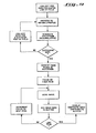
- the programming process to find the "superfocus” image is illustrated in the flow chart of Figure 9.
- the "superfocus” image is the image of an entire scanned ⁇ site or area on the wafer surface utilizing the information obtained by focusing the optical system at different levels.
- the image is displayed in the image display monitor 24a (Fig. 1) after the correct signals for the two dimensional video matrix are determined by the computer system 22 and stored in the video display memory 29.
- the V(z) data (for making the initial profile) is collected along a scan line at the center of the scanning field. This means that the x scanning line utilized is one halfway down the x-y maxtrix which is to be ultimately displayed in monitor 24a.
- the x-z profile is then obtained in the manner previously described, and a V(z) histogram (as in Fig. 8) is generated and displayed.
- the computer next asks the question whether or not the data provided by scanning along a single line is sufficient. For example, if the pattern within the entire x-y frame includes features which cannot be captured in a single x-line scan, then the y stage 32 must be driven to move the scanning mechanism 46 to a new location to provide a second x-line scan. This generates a new z profile which can be utilized for making linewidth measurements, and the z data obtained therefrom is simply added to the previously stored data in the histogram generating subroutine so that the data therein is accumulative.
- the main peaks (or z levels of interest) in the histogram are identified in the manner previously pointed out. This can be done manually by the operator or accomplished by conventional computer analysis techniques.
- the focus control meachanism 28 then moves the optical imaging system to focus on the first peak, i.e., the first level of interest, and the entire x-y plane is scanned and the data recorded. This data is stored in a buffer, and the focus control mechanism moves the imaging system to focus at the second peak, i.e., the second level of interest wherein the process is repeated with the new data being added to the previously stored data in the buffer.
- each level of interest is scanned with all of the data for each x, y position being accumulated in a plurality of x, y matrices.
- the data can then be displayed as a single plane of data on the image display monitor 24a with the data for any given (x, y) point on the screen being derived from the accumulated information from all of the scanned levels.
- a second method of display involves simply adding all of the R signal values obtained at the different scan levels for each x, y position.
- An alternative to the foregoing method of display to improve the sharpness and quality of the image is to add the different R signal values for each x, y position but set a threshold level for each scan plane so that the grossly out-of-focus data would be set to zero. This threshold level could vary from plane to plane so that the sharpest possible image would be provided.
- Another alternative method of display would be to use only the maximum reflectivity signal at each x, y position so that the generated display image represents the x, z profile of Figure 8 taken at each y level of the composite x, y matrix.
- the actual z vs. x profiles for each such y level could also be generated and stored.
- Such data could be displayed either graphically in a isometric (x, y, z) plot or used to modulate the intensity at each x, y position in a two dimensional display.
- the initial generation of a z-axis profile or cross-sectional image of the wafer surface permits all of the relevant wafer scanning data to be subsequently obtained in a rapid and highly efficient manner.
- direct linewidth measurements can be made directly from the z-axis profile more easily and more accurately than by utilizing conventional linewidth scanning techniques.
- the initial generation of a z-axis profile by the computer permits a ready analysis (either by the operator or automatically by the apparatus) after scanning a single line(or a few lines) to develop the program for scanning a complete site or area on the wafer surface so that the computer time and storage capacity is used most effectively. This is accomplished by first identifying and then scanning only those particular levels of interest which provide all of the information necessary for providing a complete topographical image of the surface of the semiconductor wafer.
Landscapes
- Physics & Mathematics (AREA)
- General Physics & Mathematics (AREA)
- Chemical & Material Sciences (AREA)
- Analytical Chemistry (AREA)
- Optics & Photonics (AREA)
- Life Sciences & Earth Sciences (AREA)
- Health & Medical Sciences (AREA)
- Biochemistry (AREA)
- General Health & Medical Sciences (AREA)
- Immunology (AREA)
- Pathology (AREA)
- Testing Or Measuring Of Semiconductors Or The Like (AREA)
- Length Measuring Devices By Optical Means (AREA)
- Exposure Of Semiconductors, Excluding Electron Or Ion Beam Exposure (AREA)
- Investigating Materials By The Use Of Optical Means Adapted For Particular Applications (AREA)
Applications Claiming Priority (2)
| Application Number | Priority Date | Filing Date | Title |
|---|---|---|---|
| US752160 | 1985-07-03 | ||
| US06/752,160 US4748335A (en) | 1985-04-19 | 1985-07-03 | Method and aparatus for determining surface profiles |
Publications (2)
| Publication Number | Publication Date |
|---|---|
| EP0208516A2 true EP0208516A2 (de) | 1987-01-14 |
| EP0208516A3 EP0208516A3 (de) | 1987-07-01 |
Family
ID=25025152
Family Applications (1)
| Application Number | Title | Priority Date | Filing Date |
|---|---|---|---|
| EP86305179A Withdrawn EP0208516A3 (de) | 1985-07-03 | 1986-07-03 | Verfahren und Vorrichtung zur Bestimmung von Oberflächenprofilen |
Country Status (3)
| Country | Link |
|---|---|
| US (1) | US4748335A (de) |
| EP (1) | EP0208516A3 (de) |
| JP (1) | JPH0815177B2 (de) |
Cited By (3)
| Publication number | Priority date | Publication date | Assignee | Title |
|---|---|---|---|---|
| EP0242151A1 (de) * | 1986-04-11 | 1987-10-21 | SiScan Systems, Inc. | Verfahren und Vorrichtung zum Messen von Linienbreiten durch Oberflächenprofile |
| EP0685732A1 (de) * | 1988-05-09 | 1995-12-06 | Omron Corporation | Vorrichtung zum Prüfen von Leiterplatten |
| CN114442296A (zh) * | 2020-10-30 | 2022-05-06 | 深圳市瑞图生物技术有限公司 | 一种用于显微镜的采图方法及医学检测装置、存储介质 |
Families Citing this family (51)
| Publication number | Priority date | Publication date | Assignee | Title |
|---|---|---|---|---|
| US4920273A (en) * | 1985-06-17 | 1990-04-24 | View Engineering, Inc. | Z-axis measurement system |
| US4910690A (en) * | 1986-02-14 | 1990-03-20 | Citizen Watch Co., Ltd. | Micro-dimensional measurement apparatus |
| DE3719422A1 (de) * | 1986-12-19 | 1988-06-30 | Hommelwerke Gmbh | Vorrichtung zur beruehrungsfreien messung eines abstandes von einer oberflaeche, insbesondere zur abtastung einer kontur einer oberflaeche eines werkstueckes laengs eines messweges |
| JPH07107481B2 (ja) * | 1987-05-21 | 1995-11-15 | アンリツ株式会社 | 変位測定装置 |
| US4876455A (en) * | 1988-02-25 | 1989-10-24 | Westinghouse Electric Corp. | Fiber optic solder joint inspection system |
| US4914601A (en) * | 1988-02-25 | 1990-04-03 | Hewlett-Packard Company | Method for profiling wafers and for locating dies thereon |
| JPH02170279A (ja) * | 1988-12-23 | 1990-07-02 | Hitachi Ltd | 被検査対象パターンの欠陥検出方法及びその装置 |
| US4988202A (en) * | 1989-06-28 | 1991-01-29 | Westinghouse Electric Corp. | Solder joint inspection system and method |
| US5124927A (en) * | 1990-03-02 | 1992-06-23 | International Business Machines Corp. | Latent-image control of lithography tools |
| US5006722A (en) * | 1990-03-02 | 1991-04-09 | Intec Corp. | Flaw annunciator with a controllable display means for an automatic inspection system |
| US5184021A (en) * | 1991-06-24 | 1993-02-02 | Siscan Systems, Inc. | Method and apparatus for measuring the dimensions of patterned features on a lithographic photomask |
| US5248876A (en) * | 1992-04-21 | 1993-09-28 | International Business Machines Corporation | Tandem linear scanning confocal imaging system with focal volumes at different heights |
| US5543918A (en) * | 1995-01-06 | 1996-08-06 | International Business Machines Corporation | Through-the-lens confocal height measurement |
| JP2822937B2 (ja) * | 1995-07-17 | 1998-11-11 | 株式会社日立製作所 | 半導体装置の製造システム及び欠陥検査方法 |
| US5953126A (en) * | 1996-10-17 | 1999-09-14 | Lucid Inc | Optical profilometry |
| US5963329A (en) * | 1997-10-31 | 1999-10-05 | International Business Machines Corporation | Method and apparatus for measuring the profile of small repeating lines |
| JPH11144496A (ja) * | 1997-11-10 | 1999-05-28 | Nec Corp | Lsiセル位置情報出力装置、出力方法およびlsiセル位置情報出力プログラムの記録媒体 |
| US6275770B1 (en) * | 1999-05-27 | 2001-08-14 | Ipec Precision Inc. | Method to remove station-induced error pattern from measured object characteristics and compensate the measured object characteristics with the error |
| DE10005852C2 (de) * | 2000-02-10 | 2002-01-17 | Nano Focus Mestechnik Gmbh | Verfahren zur Herstellung von Höhenbildern technischer Oberflächen in mikroskopischer Auflösung |
| US7518652B2 (en) * | 2000-05-03 | 2009-04-14 | Aperio Technologies, Inc. | Method and apparatus for pre-focus in a linear array based slide scanner |
| US6963076B1 (en) * | 2000-07-31 | 2005-11-08 | Xerox Corporation | System and method for optically sensing defects in OPC devices |
| US6587600B1 (en) * | 2000-08-15 | 2003-07-01 | Floor Corporation | Methods and apparatus for producing topocompositional images |
| US7115858B1 (en) | 2000-09-25 | 2006-10-03 | Nanometrics Incorporated | Apparatus and method for the measurement of diffracting structures |
| JP2002195819A (ja) * | 2000-12-27 | 2002-07-10 | Nikon Corp | 形状測定方法、形状測定装置、露光方法、露光装置、及びデバイス製造方法 |
| KR100416791B1 (ko) * | 2001-03-19 | 2004-01-31 | 삼성전자주식회사 | 반도체 웨이퍼 검사용 현미경장치 및 그 검사방법 |
| US6898537B1 (en) | 2001-04-27 | 2005-05-24 | Nanometrics Incorporated | Measurement of diffracting structures using one-half of the non-zero diffracted orders |
| US6713753B1 (en) | 2001-07-03 | 2004-03-30 | Nanometrics Incorporated | Combination of normal and oblique incidence polarimetry for the characterization of gratings |
| KR20030016935A (ko) * | 2001-08-23 | 2003-03-03 | 광주과학기술원 | 광섬유 렌즈의 초점거리를 이용한 물질의 두께 측정장치및 그 방법 |
| US7061615B1 (en) | 2001-09-20 | 2006-06-13 | Nanometrics Incorporated | Spectroscopically measured overlay target |
| US7065239B2 (en) * | 2001-10-24 | 2006-06-20 | Applied Materials, Inc. | Automated repetitive array microstructure defect inspection |
| US6982793B1 (en) | 2002-04-04 | 2006-01-03 | Nanometrics Incorporated | Method and apparatus for using an alignment target with designed in offset |
| US6949462B1 (en) | 2002-04-04 | 2005-09-27 | Nanometrics Incorporated | Measuring an alignment target with multiple polarization states |
| JP3668777B2 (ja) * | 2002-07-09 | 2005-07-06 | 独立行政法人国立高等専門学校機構 | 研削工具の砥粒突出量測定装置及び測定方法 |
| US6992764B1 (en) | 2002-09-30 | 2006-01-31 | Nanometrics Incorporated | Measuring an alignment target with a single polarization state |
| KR100524194B1 (ko) * | 2003-06-30 | 2005-10-26 | 삼성전자주식회사 | 웨이퍼의 표면 검사 방법 및 장치 |
| JP4708143B2 (ja) * | 2005-09-30 | 2011-06-22 | シスメックス株式会社 | 自動顕微鏡及びこれを備える分析装置 |
| DE102006019384B4 (de) * | 2006-04-26 | 2015-10-22 | Carl Zeiss Microscopy Gmbh | Mikroskop und Mikroskopierverfahren zur Messung des Oberflächenprofils eines Objekts |
| US8698106B2 (en) * | 2008-04-28 | 2014-04-15 | Varian Semiconductor Equipment Associates, Inc. | Apparatus for detecting film delamination and a method thereof |
| CN101782369B (zh) * | 2009-01-16 | 2012-09-19 | 鸿富锦精密工业(深圳)有限公司 | 影像量测对焦系统及方法 |
| WO2012159651A1 (en) | 2011-05-20 | 2012-11-29 | Universitat Politècnica De Catalunya | Method and device for non-contact measuring surfaces |
| US9360306B2 (en) * | 2011-09-09 | 2016-06-07 | Inspecto Inc. | Three-dimensional profile measurement apparatus and method using amplitude size of projection grid |
| CN103033129B (zh) * | 2011-10-07 | 2015-10-21 | 财团法人工业技术研究院 | 光学设备及光学定址方法 |
| JP5955574B2 (ja) * | 2012-02-03 | 2016-07-20 | 株式会社東光高岳 | 立体形状計測装置 |
| KR101896903B1 (ko) * | 2012-03-07 | 2018-09-13 | 삼성전자주식회사 | 주사 전자 현미경을 이용하여 소자의 단차를 측정하는 방법 및 단차 측정 장치 |
| EP2693271A1 (de) * | 2012-08-02 | 2014-02-05 | LayTec AG | Vorrichtung und Verfahren zum Messen der Abmessungen von 1-dimensionalen und 0-dimensionalen Nanostrukturen in Echtzeit während des Epitaxialwachstums |
| JP5983568B2 (ja) | 2013-09-11 | 2016-08-31 | トヨタ自動車株式会社 | 車両下部構造 |
| JP2016148569A (ja) * | 2015-02-12 | 2016-08-18 | キヤノン株式会社 | 画像測定方法、及び画像測定装置 |
| CN107407551B (zh) | 2015-02-18 | 2020-06-09 | 雅培实验室 | 用于使显微镜自动聚焦到基片上的方法、系统及装置 |
| TWI596359B (zh) * | 2015-12-31 | 2017-08-21 | 致茂電子股份有限公司 | 一種抑制雷射光斑雜訊提升穩定性之三維形貌掃描系統 |
| JP7017239B2 (ja) * | 2018-06-25 | 2022-02-08 | 株式会社ブイ・テクノロジー | 露光装置および高さ調整方法 |
| CN114322847B (zh) * | 2022-03-15 | 2022-05-31 | 北京精雕科技集团有限公司 | 单方向扫描传感器测量数据矢量化方法及装置 |
Citations (3)
| Publication number | Priority date | Publication date | Assignee | Title |
|---|---|---|---|---|
| DE2741807A1 (de) * | 1977-09-16 | 1979-03-29 | Friedrich Dipl Ing Ertl | Fokussierungsverfahren zur optisch beruehrungslosen laengenmessung und vorrichtung zur durchfuehrung des verfahrens |
| EP0013325A2 (de) * | 1978-12-29 | 1980-07-23 | International Business Machines Corporation | Optische Messeinrichtung zur Bestimmung des Abstands zwischen kantenförmigen Strukturen auf Oberflächen |
| US4505585A (en) * | 1981-03-31 | 1985-03-19 | Olympus Optical Co., Ltd. | System for detecting defects on an optical surface |
Family Cites Families (12)
| Publication number | Priority date | Publication date | Assignee | Title |
|---|---|---|---|---|
| US102104A (en) * | 1870-04-19 | Improvement in elastic rolls | ||
| FR1534762A (fr) * | 1967-05-18 | 1968-08-02 | Cilas | Procédé et dispositif de palpage optique |
| JPS5263755A (en) * | 1975-11-22 | 1977-05-26 | Nippon Chemical Ind | Pattern line width measuring device |
| US4194127A (en) * | 1976-01-20 | 1980-03-18 | Swiss Aluminium Ltd. | Process and device for checking substrate wafers |
| GB1595422A (en) * | 1977-04-28 | 1981-08-12 | Nat Res Dev | Scaning microscopes |
| DE2910875C2 (de) * | 1979-03-20 | 1985-11-14 | Kernforschungszentrum Karlsruhe Gmbh, 7500 Karlsruhe | Verfahren zur automatischen Scharfeinstellung |
| US4473750A (en) * | 1980-07-25 | 1984-09-25 | Hitachi, Ltd. | Three-dimensional shape measuring device |
| US4576479A (en) * | 1982-05-17 | 1986-03-18 | Downs Michael J | Apparatus and method for investigation of a surface |
| IT1198660B (it) * | 1983-08-02 | 1988-12-21 | Ottica Ist Naz | Profilometro ottico multifocale per dispersione |
| US4600832A (en) * | 1983-10-28 | 1986-07-15 | Nanometrics Incorporated | Method and apparatus for automatic optical focusing on an optically discernible feature on an object |
| JP2539778B2 (ja) * | 1984-11-22 | 1996-10-02 | 株式会社日立製作所 | 検査方法および検査装置 |
| JPS61182508A (ja) * | 1985-02-08 | 1986-08-15 | Hitachi Ltd | 微少段差計測装置 |
-
1985
- 1985-07-03 US US06/752,160 patent/US4748335A/en not_active Expired - Lifetime
-
1986
- 1986-07-02 JP JP61155929A patent/JPH0815177B2/ja not_active Expired - Fee Related
- 1986-07-03 EP EP86305179A patent/EP0208516A3/de not_active Withdrawn
Patent Citations (3)
| Publication number | Priority date | Publication date | Assignee | Title |
|---|---|---|---|---|
| DE2741807A1 (de) * | 1977-09-16 | 1979-03-29 | Friedrich Dipl Ing Ertl | Fokussierungsverfahren zur optisch beruehrungslosen laengenmessung und vorrichtung zur durchfuehrung des verfahrens |
| EP0013325A2 (de) * | 1978-12-29 | 1980-07-23 | International Business Machines Corporation | Optische Messeinrichtung zur Bestimmung des Abstands zwischen kantenförmigen Strukturen auf Oberflächen |
| US4505585A (en) * | 1981-03-31 | 1985-03-19 | Olympus Optical Co., Ltd. | System for detecting defects on an optical surface |
Non-Patent Citations (2)
| Title |
|---|
| APPLIED OPTICS, vol. 24, no. 5, 1st March 1985, pages 691-696, Optical Society of America, New York, US; Y. ICHIOKA et al.: "Digital scanning laser microscope" * |
| JOURNAL OF APPLIED PHYSICS, vol. 53, no. 7, July 1982, pages 5320-5322, American Institute of Physics, New York, US; D.K. HAMILTON et al.: "Surface profile measurement using the confocal microscope" * |
Cited By (5)
| Publication number | Priority date | Publication date | Assignee | Title |
|---|---|---|---|---|
| EP0242151A1 (de) * | 1986-04-11 | 1987-10-21 | SiScan Systems, Inc. | Verfahren und Vorrichtung zum Messen von Linienbreiten durch Oberflächenprofile |
| EP0685732A1 (de) * | 1988-05-09 | 1995-12-06 | Omron Corporation | Vorrichtung zum Prüfen von Leiterplatten |
| EP0687901A1 (de) * | 1988-05-09 | 1995-12-20 | Omron Corporation | Vorrichtung und Verfahren zur Anzeige der Ergebnisse einer Leiterplattenprüfung |
| CN114442296A (zh) * | 2020-10-30 | 2022-05-06 | 深圳市瑞图生物技术有限公司 | 一种用于显微镜的采图方法及医学检测装置、存储介质 |
| CN114442296B (zh) * | 2020-10-30 | 2024-06-04 | 深圳市瑞图生物技术有限公司 | 一种用于显微镜的采图方法及医学检测装置、存储介质 |
Also Published As
| Publication number | Publication date |
|---|---|
| JPH0815177B2 (ja) | 1996-02-14 |
| EP0208516A3 (de) | 1987-07-01 |
| JPS6314426A (ja) | 1988-01-21 |
| US4748335A (en) | 1988-05-31 |
Similar Documents
| Publication | Publication Date | Title |
|---|---|---|
| US4748335A (en) | Method and aparatus for determining surface profiles | |
| US4707610A (en) | Method and apparatus for measuring surface profiles | |
| US4689491A (en) | Semiconductor wafer scanning system | |
| US6640014B1 (en) | Automatic on-the-fly focusing for continuous image acquisition in high-resolution microscopy | |
| US3866038A (en) | Apparatus for measuring surface flatness | |
| US10412311B2 (en) | Focus adjustment for surface part inspection | |
| EP0176358B1 (de) | Bildaufnahmegerät | |
| EP1789831B1 (de) | Fokussierungsverfahren zur schnellen digitalisierung von mikroskop-objektträgern und trägerverschiebungseinrichtung, fokussierungsoptik und optischer entfernungsmesser | |
| US5479252A (en) | Laser imaging system for inspection and analysis of sub-micron particles | |
| CN1068677C (zh) | 原子力显微镜 | |
| US5994691A (en) | Near-field scanning optical microscope | |
| JP3042187B2 (ja) | リトグラフ・ホトマスクのパターン化された構造物の寸法を測定する方法および装置 | |
| US20040129858A1 (en) | Automatic focussing device for an optical appliance | |
| US6594006B1 (en) | Method and array for detecting the position of a plane scanned with a laser scanner | |
| JPS6188107A (ja) | ウエ−ハ検査装置 | |
| US7247825B2 (en) | Method and apparatus for scanning a specimen using an optical imaging system | |
| US6576902B2 (en) | Correction method of scanning electron microscope | |
| JPH1068616A (ja) | 形状計測装置 | |
| JP4603177B2 (ja) | 走査型レーザ顕微鏡 | |
| JPS63131116A (ja) | 共焦点顕微鏡 | |
| JPH077653B2 (ja) | 走査電子顕微鏡による観察装置 | |
| US4601581A (en) | Method and apparatus of determining the true edge length of a body | |
| US6824056B1 (en) | Auto-focus method for a scanning microscope | |
| WO2006097123A1 (en) | Autofocussing system for microscope systems | |
| KR20040108144A (ko) | 슬릿빔을 이용한 현미경의 자동초점조절장치 |
Legal Events
| Date | Code | Title | Description |
|---|---|---|---|
| PUAI | Public reference made under article 153(3) epc to a published international application that has entered the european phase |
Free format text: ORIGINAL CODE: 0009012 |
|
| AK | Designated contracting states |
Kind code of ref document: A2 Designated state(s): CH DE FR GB LI NL |
|
| PUAL | Search report despatched |
Free format text: ORIGINAL CODE: 0009013 |
|
| RHK1 | Main classification (correction) |
Ipc: G01B 11/24 |
|
| AK | Designated contracting states |
Kind code of ref document: A3 Designated state(s): CH DE FR GB LI NL |
|
| 17P | Request for examination filed |
Effective date: 19871211 |
|
| 17Q | First examination report despatched |
Effective date: 19890221 |
|
| STAA | Information on the status of an ep patent application or granted ep patent |
Free format text: STATUS: THE APPLICATION IS DEEMED TO BE WITHDRAWN |
|
| 18D | Application deemed to be withdrawn |
Effective date: 19900403 |
|
| RIN1 | Information on inventor provided before grant (corrected) |
Inventor name: SMITH, IAN R. Inventor name: BENNETT, SIMON D. Inventor name: LINDOW, JAMES T. |