EP0208081A1 - Procédé et dispositif d'ouverture pour imprimés pliés de manière excentrée - Google Patents
Procédé et dispositif d'ouverture pour imprimés pliés de manière excentrée Download PDFInfo
- Publication number
- EP0208081A1 EP0208081A1 EP86106243A EP86106243A EP0208081A1 EP 0208081 A1 EP0208081 A1 EP 0208081A1 EP 86106243 A EP86106243 A EP 86106243A EP 86106243 A EP86106243 A EP 86106243A EP 0208081 A1 EP0208081 A1 EP 0208081A1
- Authority
- EP
- European Patent Office
- Prior art keywords
- printed products
- opening
- area
- collecting
- product
- Prior art date
- Legal status (The legal status is an assumption and is not a legal conclusion. Google has not performed a legal analysis and makes no representation as to the accuracy of the status listed.)
- Granted
Links
Images


Classifications
-
- B—PERFORMING OPERATIONS; TRANSPORTING
- B65—CONVEYING; PACKING; STORING; HANDLING THIN OR FILAMENTARY MATERIAL
- B65H—HANDLING THIN OR FILAMENTARY MATERIAL, e.g. SHEETS, WEBS, CABLES
- B65H5/00—Feeding articles separated from piles; Feeding articles to machines
- B65H5/30—Opening devices for folded sheets or signatures
- B65H5/308—Opening devices for folded sheets or signatures the folded sheets or signatures travelling in hanging position
-
- B—PERFORMING OPERATIONS; TRANSPORTING
- B42—BOOKBINDING; ALBUMS; FILES; SPECIAL PRINTED MATTER
- B42B—PERMANENTLY ATTACHING TOGETHER SHEETS, QUIRES OR SIGNATURES OR PERMANENTLY ATTACHING OBJECTS THERETO
- B42B9/00—Devices common to machines for carrying out the processes according to more than one of the preceding main groups
-
- B—PERFORMING OPERATIONS; TRANSPORTING
- B65—CONVEYING; PACKING; STORING; HANDLING THIN OR FILAMENTARY MATERIAL
- B65H—HANDLING THIN OR FILAMENTARY MATERIAL, e.g. SHEETS, WEBS, CABLES
- B65H39/00—Associating, collating, or gathering articles or webs
- B65H39/02—Associating,collating or gathering articles from several sources
- B65H39/06—Associating,collating or gathering articles from several sources from delivery streams
-
- B—PERFORMING OPERATIONS; TRANSPORTING
- B65—CONVEYING; PACKING; STORING; HANDLING THIN OR FILAMENTARY MATERIAL
- B65H—HANDLING THIN OR FILAMENTARY MATERIAL, e.g. SHEETS, WEBS, CABLES
- B65H2301/00—Handling processes for sheets or webs
- B65H2301/40—Type of handling process
- B65H2301/43—Gathering; Associating; Assembling
- B65H2301/436—Gathering; Associating; Assembling on saddles
- B65H2301/4361—Gathering; Associating; Assembling on saddles on a rotary carrier rotating around an axis parallel to the saddles
-
- B—PERFORMING OPERATIONS; TRANSPORTING
- B65—CONVEYING; PACKING; STORING; HANDLING THIN OR FILAMENTARY MATERIAL
- B65H—HANDLING THIN OR FILAMENTARY MATERIAL, e.g. SHEETS, WEBS, CABLES
- B65H2301/00—Handling processes for sheets or webs
- B65H2301/40—Type of handling process
- B65H2301/44—Moving, forwarding, guiding material
- B65H2301/447—Moving, forwarding, guiding material transferring material between transport devices
- B65H2301/4471—Grippers, e.g. moved in paths enclosing an area
- B65H2301/44712—Grippers, e.g. moved in paths enclosing an area carried by chains or bands
-
- B—PERFORMING OPERATIONS; TRANSPORTING
- B65—CONVEYING; PACKING; STORING; HANDLING THIN OR FILAMENTARY MATERIAL
- B65H—HANDLING THIN OR FILAMENTARY MATERIAL, e.g. SHEETS, WEBS, CABLES
- B65H2301/00—Handling processes for sheets or webs
- B65H2301/40—Type of handling process
- B65H2301/44—Moving, forwarding, guiding material
- B65H2301/447—Moving, forwarding, guiding material transferring material between transport devices
- B65H2301/44795—Saddle conveyor with saddle member extending transversally to transport direction
-
- B—PERFORMING OPERATIONS; TRANSPORTING
- B65—CONVEYING; PACKING; STORING; HANDLING THIN OR FILAMENTARY MATERIAL
- B65H—HANDLING THIN OR FILAMENTARY MATERIAL, e.g. SHEETS, WEBS, CABLES
- B65H2404/00—Parts for transporting or guiding the handled material
- B65H2404/30—Chains
- B65H2404/32—Saddle conveyor
Definitions
- the present invention relates to a method and a device for opening printed products folded outside the center according to the preamble of claim 1 and claim 6 and to the use of this device in a device for collecting printed products folded outside the center according to the preamble of claim 18.
- the eccentrically folded, openable printed products are fed with their folded edge leading in a backward sloping position (EP-OS 0 095 603 and the corresponding US Pat. No. 4,489,930).
- the printed products are gripped on this fold edge by grippers of a conveyor pointing backwards with respect to the conveying direction.
- An opening device arranged below the conveyor is equipped with rotating, controlled clamps which serve to briefly hold the protruding edge section (called pre-fold) on the upper part of the printed products being fed. Downstream of the clamp run is an acceleration belt that is driven at a higher speed than the clamps.
- the present invention is based on the object of providing a method and a device of the type mentioned at the outset which, in a simple manner, enable the printed products to be opened safely.
- the printed products are fed in advance with their open side edge opposite the fold, on which one product part protrudes over the other product part, it is possible to securely grasp the one product part by means of the holding elements, because the product part to be detected can easily be caught in the effective range of the Retaining organs can be introduced.
- the captured printed product part is then moved along a path that is preferably curved downwards and backwards moves another part of the printed product away, while the printed product and thus also the last-mentioned other printed product part is conveyed further by the conveyor. This ensures that the two printed product parts are separated even if they stick together more than usual.
- the opening device according to the invention is particularly suitable for use in a device for collecting printed products folded outside the center according to claims 18 and 19.
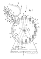
- This collecting device 1 has a frame 2 with bearing blocks 3, 3 ', in which the shaft 4 of a collecting drum 5 is mounted.
- Two disk-shaped bearing elements 6, 7 are fastened to this shaft 4 at a distance from one another, between which a number of collecting conveyors 8 are arranged, which are rotatably mounted in the bearing elements 6 and 7.
- These collecting conveyors 8 run parallel to one another and to the shaft 4 of the collecting drum 5 and are arranged around this shaft 4.
- a sprocket 9 On the shaft 4 there is a sprocket 9, over which a chain 10 is guided, which extends over another sprocket 11. The latter sits on the output shaft of one Drive 12, by means of which the collecting drum 5 together with the collecting conveyors 8 is driven in the direction of the arrow C.
- the axis of rotation is designated 4a.
- a simple embodiment of such guide means is shown schematically in FIG.
- a further sprocket 14 of the same size is also rotatably mounted.
- This sprocket 14 is in engagement with a chain 15 which is guided via a sprocket 16 which is fixedly and coaxially to the shaft 4 on the bearing block 3. All chain wheels 13 are in engagement with a chain 17 guided over this chain. This arrangement ensures that the collecting conveyors 8 maintain their vertical position during their rotation about the axis of rotation 4a.
- each feed conveyor has grippers 22 arranged at a mutual distance, the construction of which will be explained in more detail with reference to FIG. 3.
- each feed conveyor 18 Arranged below each feed conveyor 18 is an opening device 23, only shown schematically in FIG. 2, the structure of which will be described in more detail with reference to FIGS. 3 to 8.
- This opening device 23 has circumferential retaining clips 24 which, in a manner still to be explained, serve for the temporary detection of one part of the printed products 19.
- the printed products 19 fed by the feed conveyor 18 and opened by means of the opening device 23 are placed astride the collecting conveyor 8.
- Each collecting conveyor 8 is equipped with a conveyor device 25 (FIG. 1), not shown, which feeds the printed products 19, 20, 21 in the longitudinal direction of the collecting conveyor 8, ie in the direction of the arrow D.
- the drive of the conveyor device is preferably derived from the relative rotary movement between the individual collecting conveyors 8 and the bearing elements 6, 7.
- the feed speed of the conveying devices is selected such that each driver 25 travels a distance in the course of a revolution around the axis 4a, the length of which corresponds to the distance between adjacent feed conveyors 18 or opening devices 23.
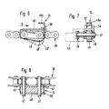
- each gripper 22 has an upper jaw 27 and a lower, movable jaw 28.
- the grippers are pivotally mounted about a pivot axis designated 22a and have a control roller 29 which cooperates with a control cam 30 arranged on one side of the channel 26 in order to hold the grippers 22 in a desired pivot position.
- a further control cam 31 is arranged, which is intended to interact with a further control roller 32 connected to the movable clamping jaw 28.
- the control roller 32 running onto the cam 31 causes the movable clamping jaw 28 to pivot away from the upper clamping jaw 27 into a release position.
- the movable clamping jaw 28 is locked in a suitable manner, for example by means of a torsion spring, in its clamping position in which, together with the upper clamping jaw 27, they hold the printed products 19 on their fold 33.
- the grippers 22 are directed towards the front in the conveying direction E of the conveyor 18, that is to say they have an open mouth.
- the printed products 19 are therefore fed with their open side edge 34 opposite the fold 33 to the opening device 23 in advance.
- the printed products 19 are folded outside the middle, which means that one Product part 19a protrudes on said open side edge 34 above the other product part 19b.
- the projecting edge region of the product part 19a which is called the pre-fold, is designated by 35.
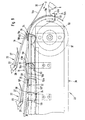
- the conveying direction E of the conveyor 18 is directed obliquely downward in the region of the opening device 23.
- the supplied printed products 19 also assume a position which slopes obliquely towards the front in their conveying direction E.
- the printed products 19 are fed in such a way that the product part 19a lies with the projecting edge section 35 on the underside.
- the retaining clips 24 of the opening device 23 are fastened at regular intervals to a chain 36 driven in rotation.
- the latter is guided over two sprockets 37 and 38, of which the sprocket 37 is driven such that the chain 36 rotates together with the retaining clips 24 in the direction of arrow F (FIG. 3).
- a drive chain 39 of the drive of the chain wheel 37 is shown purely schematically. With the sprocket 37 rotating, a deflection wheel 40 is connected, over which a round belt 41 is guided. The other deflection wheel for the endless belt 41 is not shown in FIG. 3.
- the direction of rotation of the belt 41 is designated G.
- the printed products 19 fed by the feed conveyor 19 come with their open side edge 34 to rest on the upper run of the belt 41 upstream of the opening device 23 and are thereby brought into the correct position for later clamping by the holding clamps 24.
- FIGS. 4 and 5 in each of which only the left and right halves of the opening device are shown, two chains 36 arranged at a distance from one another and running parallel to one another are provided with retaining clips 24 attached to them. Accordingly, there are also two sprockets 37 and 38, respectively, which sit on shafts designated 42 and 43, respectively. The latter are rotatably supported in side bearing plates 44 and 45 (FIGS. 4 and 5). The chains 36 are guided in guides 46, as can be seen in particular from FIGS. 4 and 5.
- the retaining clips 24 are formed by a curved spring element fastened to the holder 48 at one end. At the other end, this spring element 49 is angled to a clamping finger 49a, as can be seen in FIG. 6.
- the spring element 49 is shown in broken lines in its lower rest or clamping position, which it assumes automatically due to its spring elasticity. From this lower rest position, the spring element 49 can be moved in a manner to be described into the upper receiving or release position, which is shown in FIG. 6 with solid lines.
- the retaining clips 24 run through longitudinal slots 50 and 51 in a support plate 52 (FIGS. 4 and 5).
- This support plate 52 has a straight section 52a and one in the direction of movement F of the retaining clips 24 seen subsequent curved section 52b.
- This curved section 52b runs at a distance around the chain wheel 38, as shown in FIG. 3.
- the support plate 52 is supported by supports 53 which are fastened to a cross member 54 which extends between the side plates 44 and 45 (FIGS. 4 and 5).
- the straight section 52a of the support plate 52 is arranged to drop downward in the direction of movement F of the retaining clips 24 and thus runs essentially in the same direction as the region of the movement path of the grippers 22 above the opening device 23.
- a control cam 55 is arranged below the straight section 52a of the support plate 52, onto which the retaining clips 24 run with a run-up surface 49 '(FIG. 6) of the spring elements 49 and which raise the spring elements 49 from the lower rest or clamping position to the upper one Release position causes.
- a fixed control cam 56 is provided adjacent to the sprocket 38 and, like the control cam 55, serves to lift the spring elements 49 from the lower clamping position into the upper release position.
- each spring element 49 On both sides of each spring element 49, two stop cams 57 and 58 are arranged, which are fastened to the holder 48. At these stop cams 57, 58, the printed products 19 come to a stop with their leading side edge 34 in a manner still to be described.
- the opening of the printed products 19 fed by the feed conveyor 18 by means of the opening device 23 is done in the following manner.
- the printed products 19 held by the grippers 22 on their fold 33 come with their leading side edge 34 to rest on the circumferential belt 41, as a result of which the printed products 19 are brought into an inclined position that slopes forward.
- the printed products 19 pass from the belt 41 onto the straight section 52a of the support plate 52, on which they rest with the projecting edge section 35 of the product part 19 below.
- the retaining clips 24 running in the direction of the arrow F slightly precede the leading side edges 34 of the printed products 19, as can be seen from FIG. 3.
- the spring elements 49 run onto the control cam 55, the spring elements 49 are moved from the lower rest position into the upper release position, in which they are ready to receive the projecting edge section 35.
- the grippers 22 of the conveyor 18 are opened briefly, as is shown in FIG. 3 with the aid of the gripper designated 22 '.
- the lifting of the movable jaw 28 from the upper jaw 27 is effected by running the control roller 32 on the cam 31.
- a pivoting of the grippers 22 about their pivot axis 22a is prevented by the control roller 29 being supported on the associated control cam 30.
- the printed product 19 'released by briefly opening the gripper 22' slides down into the open holding clamp 24 and comes with the edge of the projecting edge portion 35 on the spring element 49 or on the stop cams 57, 58 to the stop. Now the gripper 22 is brought back into its clamping position, with the result that the printed product 19 is held on its fold 33 again.
- the retaining clip 24 now comes outside the effective range of the control cam 55.
- the spring elements 49 which are assigned to one another, now move downward into the clamping position, in which they hold the projecting edge section 35, due to their spring elasticity.
- the retaining clips 24 together with the captured edge section 35 now reach the deflection area defined by the chain wheel 38 or the area of the curved section 52b of the support plate 52 of the support plate 52, while the printed product 19, which is still held by a gripper 22, is moved further by the conveyor 18. As a result, the held product part 19a is moved away from the other printed product part 19b and is thus separated.
- a revolving collecting conveyor 8 now moves into the opening O that is formed, as shown in FIG. 3.
- the captured edge section 35 can now be released. This now happens in that the spring elements 49 run with their contact surface 49 'onto the control cam 56 and are moved from the clamping position into the release position.
- the path of movement of the grippers 22 is now designed such that the opened printed products 19 assume a hanging position in which the two printed product parts 19a and 19b on different sides of a collecting conveyor 8 run.
- the control cam 31 now causes the grippers 22 to open and the released printed product 19 straddles the collecting conveyor 8 inserted between its two parts 19a and 19b.
- the printed products 19 which are placed on the latter become - as already shown in FIGS. 1 and 2 described - advanced in the longitudinal direction of the collecting conveyor 8 to the next opening device, in which another printed product 20 or 21 opened in the manner described is placed on the printed product 19 or 19 and 20 already located on the collecting conveyor 8.
- the opening device 23 described can also be used essentially unchanged for opening printed products 19 which are fed in with the product part 19a having the projecting edge section 35 at the top. This will now be briefly explained with reference to FIG. 9, only the differences compared to the method of operation explained above with reference to FIG. 3 being discussed.
- the control curve 55 'for lifting the spring elements 49 into their release position is designed somewhat differently than the control curve 55 according to FIG. 3.
- the spring elements 49 are held in their lower rest position longer than in the exemplary embodiment according to FIG. 3 and only then lifted into the release position after the overhead printed product part 19a has come to a stop with its projecting edge section 35 on the stop cams 57, 58, as is shown in FIG. 9 with the aid of the printed product 19 'indicated by dash-dotted lines.
- the printed product 19 supplied with the above Edge section 35 on the stop cams 57, 58 the overhead printed product part 19a is raised in the region of the edge section 35 by lifting the spring elements 49.
- the printed product 19 is now advanced against the spring elements 49 until the edge region 59 of the shorter product part 19b lying below comes into the effective range of the clamping fingers 49a, ie until this edge region 59 on the spring elements 49 or the stop cams 57, 58 triggers.
- the spring elements 49 run off the control cam 55 ', they move automatically into the clamping position, in which the clamping fingers 49a hold the product part 19b located below in the region 59 of the leading side edge 34.
- the held product part 19b is now moved as described above along the curved section 52b of the support plate 52 and separated from the other product part 19a.
- a collecting conveyor 8 can intervene in the opening O formed in the process.
- stop cams 57, 58 are required for the opening of printed products 19 supplied overhead with their longer product part 19a, as described with reference to FIG. 9, these stop cams 57, 58 can be dispensed with in the embodiment according to FIG. 3 because the spring elements 49 also serve as a stop for the longer product part 19a below.
- This single collecting conveyor 8 can, for example, be a collecting chain be of conventional design.
- control curve 55 it is also possible to equip the opening devices 23 according to FIG. 3 with a control curve 55 ′ of the design shown in FIG. 9.
- suitable switching means depending on the type of supply of the printed products 19, one or the other control cam 55 or 55 'is brought into the operative position in which they interact with the spring elements 49.
- the supplied printed products 19, 20, 21 can be individual folded printed sheets or can also consist of a plurality of folded printed sheets lying one inside the other.
Priority Applications (1)
| Application Number | Priority Date | Filing Date | Title |
|---|---|---|---|
| AT86106243T ATE37013T1 (de) | 1985-07-01 | 1986-05-07 | Verfahren und vorrichtung zum oeffnen von ausserhalb der mitte gefalteten druckprodukten. |
Applications Claiming Priority (4)
| Application Number | Priority Date | Filing Date | Title |
|---|---|---|---|
| CH2828/85 | 1985-07-01 | ||
| CH2828/85A CH667620A5 (de) | 1985-07-01 | 1985-07-01 | Verfahren und vorrichtung zum sammeln von gefalzten druckbogen. |
| CH3245/85 | 1985-07-26 | ||
| CH324585A CH668408A5 (de) | 1985-07-26 | 1985-07-26 | Verfahren und vorrichtung zum oeffnen von ausserhalb der mitte gefalteten druckprodukten. |
Publications (2)
| Publication Number | Publication Date |
|---|---|
| EP0208081A1 true EP0208081A1 (fr) | 1987-01-14 |
| EP0208081B1 EP0208081B1 (fr) | 1988-09-07 |
Family
ID=25691494
Family Applications (1)
| Application Number | Title | Priority Date | Filing Date |
|---|---|---|---|
| EP86106243A Expired EP0208081B1 (fr) | 1985-07-01 | 1986-05-07 | Procédé et dispositif d'ouverture pour imprimés pliés de manière excentrée |
Country Status (7)
| Country | Link |
|---|---|
| US (1) | US4684117A (fr) |
| EP (1) | EP0208081B1 (fr) |
| JP (1) | JPH06102497B2 (fr) |
| AU (1) | AU576297B2 (fr) |
| CA (1) | CA1264167A (fr) |
| DE (1) | DE3660669D1 (fr) |
| FI (1) | FI80002C (fr) |
Cited By (9)
| Publication number | Priority date | Publication date | Assignee | Title |
|---|---|---|---|---|
| EP0518063A1 (fr) * | 1991-06-10 | 1992-12-16 | Ferag AG | Procédé et dispositif pour ouvrir et pour déposer sur un support en forme de selle des produits pliés d'imprimerie |
| EP0518064A1 (fr) * | 1991-06-10 | 1992-12-16 | Ferag AG | Procédé et appareil pour la manutention de produits imprimés |
| EP0522319A1 (fr) * | 1991-07-11 | 1993-01-13 | Ferag AG | Procédé et dispositif pour ouvrir des articles flexible pliés hors du centre |
| EP0564812A1 (fr) * | 1992-04-06 | 1993-10-13 | Ferag AG | Procédé et dispositif pour ouvrir des produits d'imprimerie pliés |
| CH684085A5 (de) * | 1991-12-04 | 1994-07-15 | Ferag Ag | Verfahren zum Oeffnen von aussermittig gefalteten Druckereiprodukten und Vorrichtung zur Durchführung des Verfahrens. |
| EP0647582A1 (fr) * | 1993-10-08 | 1995-04-12 | Ferag AG | Dispositif pour ouvrir et transporter des produits imprimés |
| US5462266A (en) * | 1992-12-04 | 1995-10-31 | Ferag Ag | Process and apparatus for opening folded printed products |
| EP0721903A1 (fr) * | 1995-01-13 | 1996-07-17 | Ferag AG | Dispositif pour ouvrir des produits imprimés et appareil pour traiter des produits imprimés |
| CH687872A5 (de) * | 1994-08-17 | 1997-03-14 | Ferag Ag | Verfahren zur kontinuierlichen Herstellung von verschiedenartigen Druckprodukten aus verschiedenen, bedruckten Druckprodukteteilen. |
Families Citing this family (17)
| Publication number | Priority date | Publication date | Assignee | Title |
|---|---|---|---|---|
| DE58903489D1 (de) * | 1988-05-11 | 1993-03-25 | Ferag Ag | Einrichtung zum verarbeiten von druckereiprodukten. |
| DE58903379D1 (de) * | 1988-05-11 | 1993-03-11 | Ferag Ag | Einrichtung zum sammeln von gefalzten druckbogen. |
| DE58900823D1 (de) * | 1988-05-11 | 1992-03-26 | Ferag Ag | Einrichtung zum zusammentragen, einstecken und sammeln von druckereiprodukten. |
| IT1219354B (it) * | 1988-06-03 | 1990-05-11 | Smyth Europ Ind Spa | Metodo e dispositivo per l'alimentazione di segnature ad una macchina cucitrice |
| DE58902352D1 (de) * | 1988-06-14 | 1992-11-05 | Ferag Ag | Einrichtung zum sammeln, zusammentragen und einstecken von druckereiprodukten. |
| CH682911A5 (de) * | 1988-08-11 | 1993-12-15 | Ferag Ag | Verfahren zum Herstellen vom mehrteiligen Druckereierzeugnissen, nach diesem Verfahren hergestelltes Druckereierzeugnis und Vorrichtung zur Durchführung des Verfahrens. |
| US5137409A (en) * | 1989-07-21 | 1992-08-11 | Ferag Ag | Joining together of printed partial products |
| DE59200888D1 (de) * | 1991-04-26 | 1995-01-19 | Ferag Ag | Verfahren und Einrichtung zum Verarbeiten von Druckereiprodukten. |
| JP2696633B2 (ja) * | 1991-11-05 | 1998-01-14 | ホリゾン・インターナショナル株式会社 | 丁合機 |
| ES2103533T3 (es) * | 1994-01-10 | 1997-09-16 | Ferag Ag | Dispositivo para encuadernar articulos impresos. |
| ATE149923T1 (de) * | 1994-01-19 | 1997-03-15 | Ferag Ag | Verfahren und vorrichtung zum klebverbinden der bogen eines mehrblättrigen gefalteten druckereiprodukts |
| DE59506062D1 (de) * | 1994-03-08 | 1999-07-08 | Ferag Ag | Vorrichtung zum Herstellen von mehrteiligen Druckerzeugnissen |
| CH690576A5 (de) * | 1995-06-30 | 2000-10-31 | Ferag Ag | Vorrichtung zum Verarbeiten von Druckereiprodukten. |
| CH689864A5 (de) * | 1995-06-30 | 1999-12-31 | Ferag Ag | Vorrichtung zum Verarbeiten von Druckereiprodukten. |
| EP0831045B1 (fr) * | 1996-09-06 | 2001-11-28 | Ferag AG | Méthode et dipositif pour l'ouverture de produits flexibles et plats |
| ATE304984T1 (de) * | 2001-07-18 | 2005-10-15 | Ferag Ag | Verfahren und vorrichtung zur wandlung eines förderstromes von flachen gegenständen |
| EP1475339A1 (fr) * | 2003-05-08 | 2004-11-10 | MASCHINENBAU OPPENWEILER BINDER GmbH & Co. KG | Procédé et dispositif pour le traitement ultérieur de produits imprimés |
Citations (4)
| Publication number | Priority date | Publication date | Assignee | Title |
|---|---|---|---|---|
| GB512870A (en) * | 1938-03-24 | 1939-09-27 | Brehmer Geb | Improvements in and relating to the feeding of folded signatures to book-stitching and like machines |
| US2969981A (en) * | 1958-06-13 | 1961-01-31 | Time Inc | Signature handling apparatus |
| US3481594A (en) * | 1967-07-10 | 1969-12-02 | Chicago Machinery Lab Inc | Signature feeding apparatus |
| EP0095603A1 (fr) * | 1982-06-01 | 1983-12-07 | Ferag AG | Dispositif d'assemblage de feuilles pliées d'imprimerie |
Family Cites Families (9)
| Publication number | Priority date | Publication date | Assignee | Title |
|---|---|---|---|---|
| CH591382A5 (fr) * | 1974-05-28 | 1977-09-15 | Ferag Ag | |
| CH586611A5 (fr) * | 1975-11-14 | 1977-04-15 | Grapha Holding Ag | |
| SE413007B (sv) * | 1977-04-12 | 1980-03-31 | Wifag Maschf | Anordning for att bilda en strom av overlappade falsade tryckprodukter |
| US4126390A (en) * | 1977-05-02 | 1978-11-21 | Eastman Kodak Company | Job stream programmer apparatus |
| CH618398A5 (fr) * | 1977-06-06 | 1980-07-31 | Ferag Ag | |
| CH630583A5 (de) * | 1978-06-30 | 1982-06-30 | Ferag Ag | Vorrichtung zum wegfoerdern von in einem schuppenstrom anfallenden flaechigen erzeugnissen, insbesondere druckprodukten. |
| CH644814A5 (de) * | 1980-01-08 | 1984-08-31 | Ferag Ag | Verfahren und vorrichtung zum oeffnen von gefalteten, gebundenen oder gehefteten mehrblaettrigen erzeugnissen, insbesondere druckprodukten. |
| US4555101A (en) * | 1984-03-13 | 1985-11-26 | Stobb, Inc. | Method and apparatus for separating signatures from a stack |
| US4641825A (en) * | 1985-05-22 | 1987-02-10 | Harris Graphics Corporation | Collator with moveable stitcher over saddle conveyor system |
-
1986
- 1986-05-07 DE DE8686106243T patent/DE3660669D1/de not_active Expired
- 1986-05-07 EP EP86106243A patent/EP0208081B1/fr not_active Expired
- 1986-06-23 US US06/877,360 patent/US4684117A/en not_active Expired - Lifetime
- 1986-06-30 CA CA000512756A patent/CA1264167A/fr not_active Expired - Fee Related
- 1986-06-30 AU AU59397/86A patent/AU576297B2/en not_active Ceased
- 1986-06-30 JP JP15395286A patent/JPH06102497B2/ja not_active Expired - Lifetime
- 1986-06-30 FI FI862781A patent/FI80002C/fi not_active IP Right Cessation
Patent Citations (4)
| Publication number | Priority date | Publication date | Assignee | Title |
|---|---|---|---|---|
| GB512870A (en) * | 1938-03-24 | 1939-09-27 | Brehmer Geb | Improvements in and relating to the feeding of folded signatures to book-stitching and like machines |
| US2969981A (en) * | 1958-06-13 | 1961-01-31 | Time Inc | Signature handling apparatus |
| US3481594A (en) * | 1967-07-10 | 1969-12-02 | Chicago Machinery Lab Inc | Signature feeding apparatus |
| EP0095603A1 (fr) * | 1982-06-01 | 1983-12-07 | Ferag AG | Dispositif d'assemblage de feuilles pliées d'imprimerie |
Cited By (14)
| Publication number | Priority date | Publication date | Assignee | Title |
|---|---|---|---|---|
| EP0518064A1 (fr) * | 1991-06-10 | 1992-12-16 | Ferag AG | Procédé et appareil pour la manutention de produits imprimés |
| EP0518063A1 (fr) * | 1991-06-10 | 1992-12-16 | Ferag AG | Procédé et dispositif pour ouvrir et pour déposer sur un support en forme de selle des produits pliés d'imprimerie |
| EP0522319A1 (fr) * | 1991-07-11 | 1993-01-13 | Ferag AG | Procédé et dispositif pour ouvrir des articles flexible pliés hors du centre |
| US5248135A (en) * | 1991-07-11 | 1993-09-28 | Ferag Ag | Method of, and apparatus for, opening flexible products folded off-center |
| CH684085A5 (de) * | 1991-12-04 | 1994-07-15 | Ferag Ag | Verfahren zum Oeffnen von aussermittig gefalteten Druckereiprodukten und Vorrichtung zur Durchführung des Verfahrens. |
| EP0564812A1 (fr) * | 1992-04-06 | 1993-10-13 | Ferag AG | Procédé et dispositif pour ouvrir des produits d'imprimerie pliés |
| US5462266A (en) * | 1992-12-04 | 1995-10-31 | Ferag Ag | Process and apparatus for opening folded printed products |
| EP0647582A1 (fr) * | 1993-10-08 | 1995-04-12 | Ferag AG | Dispositif pour ouvrir et transporter des produits imprimés |
| US5474285A (en) * | 1993-10-08 | 1995-12-12 | Ferag Ag | Apparatus for opening and further transporting printed products |
| AU678042B2 (en) * | 1993-10-08 | 1997-05-15 | Ferag Ag | Apparatus for opening and further transporting printing products |
| CH687872A5 (de) * | 1994-08-17 | 1997-03-14 | Ferag Ag | Verfahren zur kontinuierlichen Herstellung von verschiedenartigen Druckprodukten aus verschiedenen, bedruckten Druckprodukteteilen. |
| US5732939A (en) * | 1994-08-17 | 1998-03-31 | Ferag Ag | Process for the continuous production of different types of printed products from different types of product parts |
| EP0721903A1 (fr) * | 1995-01-13 | 1996-07-17 | Ferag AG | Dispositif pour ouvrir des produits imprimés et appareil pour traiter des produits imprimés |
| US5794926A (en) * | 1995-01-13 | 1998-08-18 | Ferag Ag | Device for opening printed products and apparatus for processing printed products |
Also Published As
| Publication number | Publication date |
|---|---|
| FI862781A (fi) | 1987-01-02 |
| FI862781A0 (fi) | 1986-06-30 |
| CA1264167A (fr) | 1990-01-02 |
| US4684117A (en) | 1987-08-04 |
| FI80002C (fi) | 1990-04-10 |
| JPH06102497B2 (ja) | 1994-12-14 |
| FI80002B (fi) | 1989-12-29 |
| EP0208081B1 (fr) | 1988-09-07 |
| AU5939786A (en) | 1987-01-08 |
| AU576297B2 (en) | 1988-08-18 |
| JPS6227260A (ja) | 1987-02-05 |
| DE3660669D1 (en) | 1988-10-13 |
Similar Documents
| Publication | Publication Date | Title |
|---|---|---|
| EP0208081B1 (fr) | Procédé et dispositif d'ouverture pour imprimés pliés de manière excentrée | |
| EP0346578B1 (fr) | Dispositif pour assembler, collationner et insérer des produits imprimés | |
| CH667621A5 (de) | Sammelhefter. | |
| DE2938010C2 (de) | Vorrichtung zum Ausrichten von in einer ununterbrochen, geschlossenen Reihe zugeführten Gegenständen | |
| CH649972A5 (de) | Vorrichtung zum uebereinanderlegen von einzelnen flaechigen erzeugnissen, insbesondere druckprodukten. | |
| EP0169490A1 (fr) | Dispositif pour transformer des produits pliés | |
| EP0169491A1 (fr) | Dispositif pour recevoir des produits pliés d'un cylindre à volets de pliage | |
| EP0600216B1 (fr) | Procédé et dispositif pour ouvrir des produits d'imprimerie pliés | |
| EP0564812B1 (fr) | Procédé et dispositif pour ouvrir des produits d'imprimerie pliés | |
| EP0265735B1 (fr) | Procédure et dispositif pour enlever les produits imprimés et pliés des machines d'imprimerie | |
| EP0323557B1 (fr) | Dispositif de transport de produits plats, en particulier de produits imprimés | |
| CH670619A5 (fr) | ||
| EP0336062A2 (fr) | Machine à insérer | |
| EP0551055B1 (fr) | Procédé et dispositif pour assembler des imprimés | |
| EP0218804B1 (fr) | Dispositif pour reprendre et transférer des feuilles pliées d'un dispositif de transport | |
| EP0300171B1 (fr) | Dispositif de transport pour produits plats, en particulier des produits imprimés | |
| EP0659586B1 (fr) | Procédé pour délivrer un ensemble de feuilles imprimées avec des encarts | |
| CH659641A5 (de) | Vorrichtung zum zubringen gefalteter blaetter zu einer heftmaschine. | |
| DE2832660C3 (de) | Vorrichtung zum gruppenweisen Abteilen von geschuppt übereinanderliegend geförderten Werkstücken | |
| CH669585A5 (fr) | ||
| EP0831045B1 (fr) | Méthode et dipositif pour l'ouverture de produits flexibles et plats | |
| EP1072546B1 (fr) | Convoyeur pour assembler et traiter des produits imprimés | |
| DE1786046A1 (de) | Verfahren zum Stapeln von Signaturen und Vorrichtung zur Durchfuehrung des Verfahrens | |
| DE1153383B (de) | Einrichtung zum Ablegen der bogenfoermigen Produkte einer Rotationsdruckmaschine | |
| DE1561141B2 (de) | Vorrichtung zum einfuehren von beilagen in gefaltete druckerzeugnisse |
Legal Events
| Date | Code | Title | Description |
|---|---|---|---|
| PUAI | Public reference made under article 153(3) epc to a published international application that has entered the european phase |
Free format text: ORIGINAL CODE: 0009012 |
|
| 17P | Request for examination filed |
Effective date: 19860913 |
|
| AK | Designated contracting states |
Kind code of ref document: A1 Designated state(s): AT BE DE FR GB IT NL SE |
|
| 17Q | First examination report despatched |
Effective date: 19871013 |
|
| GRAA | (expected) grant |
Free format text: ORIGINAL CODE: 0009210 |
|
| ITF | It: translation for a ep patent filed |
Owner name: FUMERO BREVETTI S.N.C. |
|
| AK | Designated contracting states |
Kind code of ref document: B1 Designated state(s): AT BE DE FR GB IT NL SE |
|
| REF | Corresponds to: |
Ref document number: 37013 Country of ref document: AT Date of ref document: 19880915 Kind code of ref document: T |
|
| GBT | Gb: translation of ep patent filed (gb section 77(6)(a)/1977) | ||
| REF | Corresponds to: |
Ref document number: 3660669 Country of ref document: DE Date of ref document: 19881013 |
|
| ET | Fr: translation filed | ||
| PLBE | No opposition filed within time limit |
Free format text: ORIGINAL CODE: 0009261 |
|
| STAA | Information on the status of an ep patent application or granted ep patent |
Free format text: STATUS: NO OPPOSITION FILED WITHIN TIME LIMIT |
|
| 26N | No opposition filed | ||
| ITTA | It: last paid annual fee | ||
| EAL | Se: european patent in force in sweden |
Ref document number: 86106243.8 |
|
| PGFP | Annual fee paid to national office [announced via postgrant information from national office to epo] |
Ref country code: FR Payment date: 19960419 Year of fee payment: 11 |
|
| PGFP | Annual fee paid to national office [announced via postgrant information from national office to epo] |
Ref country code: NL Payment date: 19960422 Year of fee payment: 11 Ref country code: BE Payment date: 19960422 Year of fee payment: 11 |
|
| PGFP | Annual fee paid to national office [announced via postgrant information from national office to epo] |
Ref country code: AT Payment date: 19960423 Year of fee payment: 11 |
|
| PG25 | Lapsed in a contracting state [announced via postgrant information from national office to epo] |
Ref country code: AT Effective date: 19970507 |
|
| PG25 | Lapsed in a contracting state [announced via postgrant information from national office to epo] |
Ref country code: BE Effective date: 19970531 |
|
| BERE | Be: lapsed |
Owner name: FERAG A.G. Effective date: 19970531 |
|
| PG25 | Lapsed in a contracting state [announced via postgrant information from national office to epo] |
Ref country code: NL Effective date: 19971201 |
|
| PG25 | Lapsed in a contracting state [announced via postgrant information from national office to epo] |
Ref country code: FR Free format text: LAPSE BECAUSE OF NON-PAYMENT OF DUE FEES Effective date: 19980130 |
|
| NLV4 | Nl: lapsed or anulled due to non-payment of the annual fee |
Effective date: 19971201 |
|
| REG | Reference to a national code |
Ref country code: FR Ref legal event code: ST |
|
| REG | Reference to a national code |
Ref country code: GB Ref legal event code: IF02 |
|
| PGFP | Annual fee paid to national office [announced via postgrant information from national office to epo] |
Ref country code: SE Payment date: 20020502 Year of fee payment: 17 Ref country code: GB Payment date: 20020502 Year of fee payment: 17 |
|
| PG25 | Lapsed in a contracting state [announced via postgrant information from national office to epo] |
Ref country code: GB Free format text: LAPSE BECAUSE OF NON-PAYMENT OF DUE FEES Effective date: 20030507 |
|
| PG25 | Lapsed in a contracting state [announced via postgrant information from national office to epo] |
Ref country code: SE Free format text: LAPSE BECAUSE OF NON-PAYMENT OF DUE FEES Effective date: 20030508 |
|
| GBPC | Gb: european patent ceased through non-payment of renewal fee |
Effective date: 20030507 |
|
| EUG | Se: european patent has lapsed | ||
| PG25 | Lapsed in a contracting state [announced via postgrant information from national office to epo] |
Ref country code: IT Free format text: LAPSE BECAUSE OF NON-PAYMENT OF DUE FEES;WARNING: LAPSES OF ITALIAN PATENTS WITH EFFECTIVE DATE BEFORE 2007 MAY HAVE OCCURRED AT ANY TIME BEFORE 2007. THE CORRECT EFFECTIVE DATE MAY BE DIFFERENT FROM THE ONE RECORDED. Effective date: 20050507 |
|
| PGFP | Annual fee paid to national office [announced via postgrant information from national office to epo] |
Ref country code: DE Payment date: 20050510 Year of fee payment: 20 |