EP0207349B1 - Saumführungskanal für Bandbehandlungsanlagen - Google Patents
Saumführungskanal für Bandbehandlungsanlagen Download PDFInfo
- Publication number
- EP0207349B1 EP0207349B1 EP86108154A EP86108154A EP0207349B1 EP 0207349 B1 EP0207349 B1 EP 0207349B1 EP 86108154 A EP86108154 A EP 86108154A EP 86108154 A EP86108154 A EP 86108154A EP 0207349 B1 EP0207349 B1 EP 0207349B1
- Authority
- EP
- European Patent Office
- Prior art keywords
- trim
- guide channel
- hem
- gripper
- channel
- Prior art date
- Legal status (The legal status is an assumption and is not a legal conclusion. Google has not performed a legal analysis and makes no representation as to the accuracy of the status listed.)
- Expired
Links
- 238000009966 trimming Methods 0.000 title claims description 8
- 238000004519 manufacturing process Methods 0.000 description 1
- 239000002184 metal Substances 0.000 description 1
- 238000000034 method Methods 0.000 description 1
- 238000000926 separation method Methods 0.000 description 1
Images
Classifications
-
- B—PERFORMING OPERATIONS; TRANSPORTING
- B21—MECHANICAL METAL-WORKING WITHOUT ESSENTIALLY REMOVING MATERIAL; PUNCHING METAL
- B21D—WORKING OR PROCESSING OF SHEET METAL OR METAL TUBES, RODS OR PROFILES WITHOUT ESSENTIALLY REMOVING MATERIAL; PUNCHING METAL
- B21D43/00—Feeding, positioning or storing devices combined with, or arranged in, or specially adapted for use in connection with, apparatus for working or processing sheet metal, metal tubes or metal profiles; Associations therewith of cutting devices
- B21D43/28—Associations of cutting devices therewith
- B21D43/287—Devices for handling sheet or strip material
-
- B—PERFORMING OPERATIONS; TRANSPORTING
- B23—MACHINE TOOLS; METAL-WORKING NOT OTHERWISE PROVIDED FOR
- B23D—PLANING; SLOTTING; SHEARING; BROACHING; SAWING; FILING; SCRAPING; LIKE OPERATIONS FOR WORKING METAL BY REMOVING MATERIAL, NOT OTHERWISE PROVIDED FOR
- B23D31/00—Shearing machines or shearing devices covered by none or more than one of the groups B23D15/00 - B23D29/00; Combinations of shearing machines
- B23D31/04—Shearing machines or shearing devices covered by none or more than one of the groups B23D15/00 - B23D29/00; Combinations of shearing machines for trimming stock combined with devices for shredding scrap
-
- B—PERFORMING OPERATIONS; TRANSPORTING
- B26—HAND CUTTING TOOLS; CUTTING; SEVERING
- B26D—CUTTING; DETAILS COMMON TO MACHINES FOR PERFORATING, PUNCHING, CUTTING-OUT, STAMPING-OUT OR SEVERING
- B26D7/00—Details of apparatus for cutting, cutting-out, stamping-out, punching, perforating, or severing by means other than cutting
- B26D7/18—Means for removing cut-out material or waste
Definitions
- the invention relates to a hem guide channel for band treatment systems, in particular trimming or slitting lines, which is arranged laterally next to the band between a pair of hem scissors and a hem processing device offset from the band guide plane, in particular hem winder, hem crusher, and hem collecting pit.
- a guide is, for example, a hem guide channel which is located on the side next to the band between the hem scissors and a further processing device, e.g. a hem crusher or the like, is arranged (US-PS 25 00 772). In order to ensure that the hem is guided as smoothly as possible in the hem guide channel, it has a relatively large cross section.
- the invention has for its object to provide a hem guide channel in which manual intervention when pulling in the beginning of the hem is not necessary and which is less sensitive to traffic jams.
- this object is achieved in that a hem pulling device with a gripper for the start of the hem which can be brought out of the hem guiding channel up to the hem scissors is arranged in or on the hem guide channel, and in that the hem pulling device is moved from a position inside the hem guide channel to a position outside when the gripper is retracted the hem guide channel is movably mounted.
- the hem guide which is narrow in the free cross section, is omitted immediately behind the hem scissors. Therefore, there can be no more traffic jams in operation if this tour is no longer required anyway.
- the transfer of the start of the hem into the hem guide channel is carried out by the hem pulling device, which is only in the transport path of the hem guide channel during the pulling process.
- the start of the hem can easily be gripped if the gripper is designed as pliers.
- the drive and / or guide rollers for the hem are arranged at the entrance of the hem guide channel and can be moved apart to form a free passage for the gripper. These guide rollers hold the start of the hem when the gripper releases the start of the hem so that it can be moved out of the transport path of the hem guide channel.
- the hem pulling device Moving the hem pulling device out of the transport path of the hem guide channel can be made possible in a simple manner by the hem pulling device being movable or pivotable transversely to the longitudinal axis of the hem guide channel.
- the hem pulling device is arranged on the outside of one of the walls of the hem guide channel, which can be introduced transversely into the hem guide channel.
- a belt 2 to be treated in a stretching / straightening system 1 is guided by an inlet-side and an outlet-side tensioning roller set 3, 4.
- a trimming device consisting of a pair of hem scissors 5 and a hem guide channel 6 is arranged.
- the trimming shear 5 consists of circular cylindrical knives 7, 8.
- the hem guide channel 6 has a rectangular cross section.
- the lower wall 9 has a part 10 which can be moved transversely to the longitudinal axis of the channel 6 and which carries a hem pulling device 11 on its outside.
- the hem pulling device 11 consists of a drive 12, e.g. a cylinder piston arrangement, an extendable pull rod 13 and a gripper 14 arranged at the free end, designed as pliers 14.
- a drive 12 e.g. a cylinder piston arrangement
- an extendable pull rod 13 e.g. a cylinder piston arrangement
- a gripper 14 arranged at the free end, designed as pliers 14.
- two driven and extendable guide rollers 15, 16 are arranged at the entrance of the hem guide channel 6.
- hem guide channel is also suitable for tape guide directions other than shown.
Landscapes
- Engineering & Computer Science (AREA)
- Mechanical Engineering (AREA)
- Life Sciences & Earth Sciences (AREA)
- Forests & Forestry (AREA)
- Treatment Of Fiber Materials (AREA)
- Winding, Rewinding, Material Storage Devices (AREA)
- Basic Packing Technique (AREA)
Description
- Die Erfindung bezieht sich auf einen Saumführungskanal für Bandbehandlungsanlagen, insbesondere Besäum- oder Längsteilanlagen, der seitlich neben dem Band zwischen einer Saumschere und einer zur Bandführungsebene versetzten Saumverarbeitungsvorrichtung, insbesondere Saumwickler, Saumzerkleinerer, Saumsammelgrube angeordnet ist.
- Bei der Herstellung ober Behandlung von Bändern, insbesondere Metallbändern, entsprechen die Bandränder in der Regel nicht den vorgegebenen Massen für das Band. Deshalb werden sie im Durchlauf mit Scheren abgetrennt. Dieses Abtrennen, das sog. Besäumen, im Durchlauf macht eine Führung der Säume erforderlich. Eine solche Führung ist beispielsweise ein Saumführungskanal, der seitlich neben dem Band zwischen der Saumschere und einer weiterverarbeitenden Vorrichtung, z.B. einem Saumzerkleinerer oder dergleichen, angeordnet ist (US-PS 25 00 772). Um eine möglichst störungsfreie Führung des Saumes im Saumführungskanal zu gewährleisten, hat dieser einen verhältnismässig grossen Querschnitt. Ein solcher Saumführungskanal kann aber aus Platzgründen nicht nahe genug an die Schere herangerückt werden, um ein selbständiges Einlaufen des Saumanfanges in den Saumführungskanal zu gewährleisten. Deshalb ist es erforderlich, entweder von Hand die Saumanfänge in den Saumführungskanal einzuführen oder aber im Querschnitt kleinere Saumführungen zwischen der Saumschere und dem Eingang des Saumführungskanales anzuordnen. Es hat sich nun gezeigt, dass in den im Querschnittverhältnismässig engen Saumführungen sich nicht selten Staus bilden. Diese Störungen des Arbeitsablaufes können nur von Hand beseitigt werden. Die Beseitigung der Staus kann aber auch Unfälle verursachen.
- Der Erfindung liegt die Aufgabe zugrunde, einen Saumführungskanal zu schaffen, bei dem ein Eingreifen von Hand beim Einziehen des Saumanfanges nicht erforderlich ist und der weniger empfindlich gegenüber Staus ist.
- Diese Aufgabe wird erfindungsgemäss dadurch gelöst, dass in oder an dem Saumführungskanal eine Saumeinziehvorrichtung mit einem aus dem Saumführungskanal heraus bis an die Saumschere heranführbaren Greifer für den Saumanfang angeordnet ist, und dass die Saumeinziehvorrichtung bei eingezogenem Greifer aus einer Stellung innerhalb des Saumführungskanales in eine Stellung ausserhalb des Saumführungskanales bewegbar gelagert ist.
- Bei dem erfindungsgemässen Saumführungskanal entfällt die im freien Querschnitt enge Saumführung unmittelbar hinter der Saumschere. Deshalb kann es im Betrieb, wenn diese Führung ohnehin nicht mehr benötigt wird, nicht mehr zu Staus kommen. Die Überführung des Saumanfanges in den Saumführungskanal wird von der Saumeinziehvorrichtung übernommen, die sich nur beim Einziehvorgang im Transportweg des Saumführungskanales befindet.
- Der Saumanfang lässt sich problemlos ergreifen, wenn der Greifer als Zange ausgebildet ist.
- Nach einer weiteren Ausgestaltung der Erfindung sind am Eingang des Saumführungskanales die Treib- und/oder Führungsrollen für den Saum angeordnet, die zur Bildung eine freien Durchganges für den Greifer auseinanderbewegbar sind. Diese Führungsrollen halten den Saumanfang, wenn der Greifer den Saumanfang freigibt, um aus dem Transportweg des Saumführungskanales herausbewegt werden zu können.
- Das Herausbewegen der Saumeinzieheinrichtung aus dem Transportweg des Saumführungskanales lässt sich auf einfache Weise dadurch ermöglichen, dass die Saumeinziehvorrichtung zur Längsachse des Saumführungskanales quer verfahrbar oder schwenkbar ist. Dabei ist nach einer besonders vorteilhaften Ausgestaltung die Saumeinziehvorrichrung auf der Aussenseite einer der Wände des Saumführungskanales angeordnet, die quer in den Saumführungskanal einbringbar ist.
- Im folgenden wird die Erfindung anhand einer Zeichnung näher beschrieben. Im einzelnen zeigen:
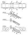
- Fig. 1 ein Band in einer Bandbehandlungsanlage, z.B. einer Streck-/Richtanlage in Aufsicht:
- Fig. 2 - 4 einen Saumführungskanal in Seitenansicht in verschiedenen Betriebsphasen beim Einziehen eines Saumanfanges.
- Ein in einer Streck-/Richtanlage 1 zu behandelndes Band 2 wird von einem einlaufseitigen und einem auslaufseitigen Spannrollensatz 3,4 geführt. An den beiden Rändern des Bandes 2 ist jeweils eine Besäumvorrichtung aus einer Saumschere 5 und einem Saumführungskanal 6 angeordnet.
- Die Besäumschere 5 besteht aus kreiszylindrischen Messern 7, 8.
- Der Saumführungskanal 6 hat einen rechteckigen Querschnitt. Die untere Wand 9 weist einen quer zur Längsachse des Kanales 6 verfahrbaren Teil 10 auf, der auf seiner Aussenseite eine Saumeinziehvorrichtung 11 trägt. Die Saumeinziehvorrichtung 11 besteht aus einem Antrieb 12, z.B. einer Zylinderkolbenanordnung, einer ausfahrbaren Zugstange 13 und einem am freien Ende angeordneten, als Zange ausgebildeten Greifer 14. Am Eingang des Saumführungskanales 6 sind zwei angetriebene und auseinanderfahrbare Führungsrollen 15,16 angeordnet.
- Im folgenden wird die Funktion des Saumführungskanales beschrieben:
- Zum Ergreifen des aus der Saumschere 5 herausragenden Saumanfanges 17 wird der Wandteil 10 in den Saumführungskanal 6 hineingefahren und nach Öffnen der Führungsrollen 15,16 die Zugstange 13 mit geöffneter Zange 14 bis nahe an die Saumschere 5 ausgefahren Fig. 2). Nach Schliessen der Zange 14 kann die Stange 13 wieder eingefahren werden, wobei sie den Saumanfang mitnimmt (Fig. 3). Sobald der Saumanfang 17 die Führungsrollen 15,16 passiert hat, können diese zusammengefahren werden und den Saumanfang einklemmen. Jetzt kann die Zange 14 wieder geöffnet werden. Nach weiterem Einziehen der Stange 13 wird der Wandteil 10 wieder aus dem Saumführungskanal 6 herausgefahren und in eine Flucht mit der übrigen Wand 9 gebracht (Fig. 4). Damit ist der freie grosse Querschnitt für die staufreie Führung des Saumes wiederhergestellt.
- Es versteht sich, dass der Saumführungskanal auch für andere Bandführungsrichtungen als dargestellt geeignet ist.
Claims (5)
Applications Claiming Priority (4)
| Application Number | Priority Date | Filing Date | Title |
|---|---|---|---|
| DE3524066 | 1985-07-05 | ||
| DE3524066 | 1985-07-05 | ||
| DE19853538777 DE3538777A1 (de) | 1985-07-05 | 1985-10-31 | Saumfuehrungskanal fuer bandbehandlungsanlagen |
| DE3538777 | 1985-10-31 |
Publications (2)
| Publication Number | Publication Date |
|---|---|
| EP0207349A1 EP0207349A1 (de) | 1987-01-07 |
| EP0207349B1 true EP0207349B1 (de) | 1989-01-18 |
Family
ID=25833745
Family Applications (1)
| Application Number | Title | Priority Date | Filing Date |
|---|---|---|---|
| EP86108154A Expired EP0207349B1 (de) | 1985-07-05 | 1986-06-14 | Saumführungskanal für Bandbehandlungsanlagen |
Country Status (2)
| Country | Link |
|---|---|
| EP (1) | EP0207349B1 (de) |
| DE (2) | DE3538777A1 (de) |
Families Citing this family (3)
| Publication number | Priority date | Publication date | Assignee | Title |
|---|---|---|---|---|
| DE3840633C2 (de) * | 1988-12-02 | 1997-04-24 | Schloemann Siemag Ag | Vorrichtung zur Führung und Überleitung des durch Saum- bzw. Streifenscheren von einem Band abgetrennten Bandsaumes zur Saumteilschere |
| DE102012201026A1 (de) | 2012-01-25 | 2013-07-25 | Sms Siemag Ag | Vorrichtung und Verfahren zum Besäumen von Bändern |
| CN111496887B (zh) * | 2020-04-19 | 2021-08-24 | 山东华航高分子材料有限公司 | 聚氯乙烯管道的定长度切割工艺 |
Family Cites Families (4)
| Publication number | Priority date | Publication date | Assignee | Title |
|---|---|---|---|---|
| US2084967A (en) * | 1936-01-20 | 1937-06-22 | Yoder Co | Mechanism for cutting sheet material |
| US2500772A (en) * | 1948-06-03 | 1950-03-14 | Armco Steel Corp | Scrap cutting shear |
| US2788853A (en) * | 1953-07-27 | 1957-04-16 | Schloemann Ag | Edge strip control in circular knife edging shears |
| DE2547911C3 (de) * | 1975-10-25 | 1980-01-31 | Aluminium Norf Gmbh, 4040 Neuss | Vorrichtung zum Entfernen des Saumschrottstreifens eines NE-Metallbandes |
-
1985
- 1985-10-31 DE DE19853538777 patent/DE3538777A1/de active Granted
-
1986
- 1986-06-14 DE DE8686108154T patent/DE3661799D1/de not_active Expired
- 1986-06-14 EP EP86108154A patent/EP0207349B1/de not_active Expired
Also Published As
| Publication number | Publication date |
|---|---|
| DE3538777C2 (de) | 1987-04-16 |
| DE3661799D1 (en) | 1989-02-23 |
| EP0207349A1 (de) | 1987-01-07 |
| DE3538777A1 (de) | 1987-01-15 |
Similar Documents
| Publication | Publication Date | Title |
|---|---|---|
| DE10113379A1 (de) | Vorschubeinrichtung, insbesondere für Cordbänder | |
| DE3303956A1 (de) | Vorrichtung zum umreifen eines quaderfoermigen gegenstandes | |
| DE2838436A1 (de) | Maschine zum einfuehren von flachen gegenstaenden in briefumschlaege | |
| EP0163849B1 (de) | Transportvorrichtung für einen Kabelkonfektionierungsautomaten | |
| EP0284918A2 (de) | Überleitvorrichtung für Bänder zwischen einer Ablaufhaspel und einer Bandbe- oder Bandverarbeitungseinrichtung | |
| DE3008030C2 (de) | Vorrichtung zum Abschneiden von zwei entkuppelten fortlaufenden Reißverschlußbändern und zum Kuppeln der abgeschnittenen Reißverschlußbänder | |
| DE3538777C2 (de) | ||
| DE4408568A1 (de) | Automatische Maschine zum Binden von Rohrbündeln oder ähnlichem | |
| CH671585A5 (de) | ||
| DE2830333B1 (de) | Vorrichtung zum Iagerichtigen Transport von Bandanfaengen laengsgeteilter Metallbaender | |
| DE3334646C2 (de) | Vorrichtung zum Falten und Positionieren von Bandabschnitten an Gewebestücken | |
| DE69114104T2 (de) | Verfahren und Vorrichtung zur Behandlung von Treibriemen auf eine automatische Weise. | |
| DE2836480B2 (de) | Vorrichtung zum Aufnehmen und Drehen eines Bandbundes | |
| EP0096777A1 (de) | Verfahren und Vorrichtung zum Entfernen von Verschlussgliedern von einem Reissverschlussband | |
| EP0034578B2 (de) | Vorrichtung zum Führen der einzelnen Streifen eines in Längsstreifen geteilten Blechbandes | |
| DE3438212A1 (de) | Anlage zum ablaengen und wickeln von wickelgut | |
| EP0387726A2 (de) | Vorrichtung zur Uebernahme, Speicherung und Abgabe von Falzprodukten | |
| DE3883025T2 (de) | Drahtlitzen-Stapelvorrichtung. | |
| CH665194A5 (de) | Einfaedelvorrichtung fuer streifenfoermiges material. | |
| DE3728628C2 (de) | ||
| EP0044881B1 (de) | Verfahren und Montagevorrichtung zur kontinuierlichen Herstellung eines Panzers für Deckenglieder- oder Rolltore | |
| DE3445864C2 (de) | ||
| DE69016586T2 (de) | Verfahren und Vorrichtung zum automatischen Einziehen eines Films. | |
| DE3030460A1 (de) | Vorrichtung zum ueberfuehren von werkstuecken von einer station zur naechsten und verfahren zum anhalten der werkstuecke | |
| DE19500656C2 (de) | Vorrichtung zum Trennen von gekrümmten Würsten von einem Wurstband |
Legal Events
| Date | Code | Title | Description |
|---|---|---|---|
| PUAI | Public reference made under article 153(3) epc to a published international application that has entered the european phase |
Free format text: ORIGINAL CODE: 0009012 |
|
| AK | Designated contracting states |
Kind code of ref document: A1 Designated state(s): CH DE FR GB IT LI |
|
| 17P | Request for examination filed |
Effective date: 19870414 |
|
| 17Q | First examination report despatched |
Effective date: 19880628 |
|
| ITF | It: translation for a ep patent filed | ||
| GRAA | (expected) grant |
Free format text: ORIGINAL CODE: 0009210 |
|
| AK | Designated contracting states |
Kind code of ref document: B1 Designated state(s): CH DE FR GB IT LI |
|
| GBT | Gb: translation of ep patent filed (gb section 77(6)(a)/1977) | ||
| REF | Corresponds to: |
Ref document number: 3661799 Country of ref document: DE Date of ref document: 19890223 |
|
| ET | Fr: translation filed | ||
| PLBE | No opposition filed within time limit |
Free format text: ORIGINAL CODE: 0009261 |
|
| STAA | Information on the status of an ep patent application or granted ep patent |
Free format text: STATUS: NO OPPOSITION FILED WITHIN TIME LIMIT |
|
| 26N | No opposition filed | ||
| PGFP | Annual fee paid to national office [announced via postgrant information from national office to epo] |
Ref country code: FR Payment date: 19910524 Year of fee payment: 6 |
|
| PGFP | Annual fee paid to national office [announced via postgrant information from national office to epo] |
Ref country code: CH Payment date: 19910527 Year of fee payment: 6 |
|
| PGFP | Annual fee paid to national office [announced via postgrant information from national office to epo] |
Ref country code: GB Payment date: 19910528 Year of fee payment: 6 |
|
| ITTA | It: last paid annual fee | ||
| PG25 | Lapsed in a contracting state [announced via postgrant information from national office to epo] |
Ref country code: GB Effective date: 19920614 |
|
| PG25 | Lapsed in a contracting state [announced via postgrant information from national office to epo] |
Ref country code: LI Effective date: 19920630 Ref country code: CH Effective date: 19920630 |
|
| GBPC | Gb: european patent ceased through non-payment of renewal fee |
Effective date: 19920614 |
|
| PG25 | Lapsed in a contracting state [announced via postgrant information from national office to epo] |
Ref country code: FR Effective date: 19930226 |
|
| REG | Reference to a national code |
Ref country code: CH Ref legal event code: PL |
|
| REG | Reference to a national code |
Ref country code: FR Ref legal event code: ST |
|
| PGFP | Annual fee paid to national office [announced via postgrant information from national office to epo] |
Ref country code: DE Payment date: 19960730 Year of fee payment: 11 |
|
| PG25 | Lapsed in a contracting state [announced via postgrant information from national office to epo] |
Ref country code: DE Free format text: LAPSE BECAUSE OF NON-PAYMENT OF DUE FEES Effective date: 19980401 |
|
| PG25 | Lapsed in a contracting state [announced via postgrant information from national office to epo] |
Ref country code: IT Free format text: LAPSE BECAUSE OF NON-PAYMENT OF DUE FEES;WARNING: LAPSES OF ITALIAN PATENTS WITH EFFECTIVE DATE BEFORE 2007 MAY HAVE OCCURRED AT ANY TIME BEFORE 2007. THE CORRECT EFFECTIVE DATE MAY BE DIFFERENT FROM THE ONE RECORDED. Effective date: 20050614 |