EP0204445B1 - Kunststoffrohrkupplungsapparat und Methode zu seiner Verwendung - Google Patents
Kunststoffrohrkupplungsapparat und Methode zu seiner Verwendung Download PDFInfo
- Publication number
- EP0204445B1 EP0204445B1 EP86303639A EP86303639A EP0204445B1 EP 0204445 B1 EP0204445 B1 EP 0204445B1 EP 86303639 A EP86303639 A EP 86303639A EP 86303639 A EP86303639 A EP 86303639A EP 0204445 B1 EP0204445 B1 EP 0204445B1
- Authority
- EP
- European Patent Office
- Prior art keywords
- pipe
- spigot
- plastic
- coupling
- sleeve
- Prior art date
- Legal status (The legal status is an assumption and is not a legal conclusion. Google has not performed a legal analysis and makes no representation as to the accuracy of the status listed.)
- Expired
Links
Images

Classifications
-
- F—MECHANICAL ENGINEERING; LIGHTING; HEATING; WEAPONS; BLASTING
- F16—ENGINEERING ELEMENTS AND UNITS; GENERAL MEASURES FOR PRODUCING AND MAINTAINING EFFECTIVE FUNCTIONING OF MACHINES OR INSTALLATIONS; THERMAL INSULATION IN GENERAL
- F16L—PIPES; JOINTS OR FITTINGS FOR PIPES; SUPPORTS FOR PIPES, CABLES OR PROTECTIVE TUBING; MEANS FOR THERMAL INSULATION IN GENERAL
- F16L37/00—Couplings of the quick-acting type
- F16L37/08—Couplings of the quick-acting type in which the connection between abutting or axially overlapping ends is maintained by locking members
- F16L37/12—Couplings of the quick-acting type in which the connection between abutting or axially overlapping ends is maintained by locking members using hooks, pawls, or other movable or insertable locking members
- F16L37/138—Couplings of the quick-acting type in which the connection between abutting or axially overlapping ends is maintained by locking members using hooks, pawls, or other movable or insertable locking members using an axially movable sleeve
-
- F—MECHANICAL ENGINEERING; LIGHTING; HEATING; WEAPONS; BLASTING
- F16—ENGINEERING ELEMENTS AND UNITS; GENERAL MEASURES FOR PRODUCING AND MAINTAINING EFFECTIVE FUNCTIONING OF MACHINES OR INSTALLATIONS; THERMAL INSULATION IN GENERAL
- F16L—PIPES; JOINTS OR FITTINGS FOR PIPES; SUPPORTS FOR PIPES, CABLES OR PROTECTIVE TUBING; MEANS FOR THERMAL INSULATION IN GENERAL
- F16L31/00—Arrangements for connecting hoses to one another or to flexible sleeves
-
- F—MECHANICAL ENGINEERING; LIGHTING; HEATING; WEAPONS; BLASTING
- F16—ENGINEERING ELEMENTS AND UNITS; GENERAL MEASURES FOR PRODUCING AND MAINTAINING EFFECTIVE FUNCTIONING OF MACHINES OR INSTALLATIONS; THERMAL INSULATION IN GENERAL
- F16L—PIPES; JOINTS OR FITTINGS FOR PIPES; SUPPORTS FOR PIPES, CABLES OR PROTECTIVE TUBING; MEANS FOR THERMAL INSULATION IN GENERAL
- F16L33/00—Arrangements for connecting hoses to rigid members; Rigid hose-connectors, i.e. single members engaging both hoses
- F16L33/22—Arrangements for connecting hoses to rigid members; Rigid hose-connectors, i.e. single members engaging both hoses with means not mentioned in the preceding groups for gripping the hose between inner and outer parts
- F16L33/225—Arrangements for connecting hoses to rigid members; Rigid hose-connectors, i.e. single members engaging both hoses with means not mentioned in the preceding groups for gripping the hose between inner and outer parts a sleeve being movable axially
Definitions
- the present invention relates to a plastic gas pipe coupling and a method of use thereof.
- plastic pipe such as polyethelene
- polyethelene pipe has become a popular conduit for underground transmission of natural gas.
- polyethelene pipe has become more and more popular in industry, the necessity of perfecting a coupling method has become apparent.
- numerous different coupling procedures have been proposed. Some coupling procedures contemplate the actual fusion of the plastic pipe to form a gas tight coupling.
- Other devices have been proposed which contemplate use of telescopically interfitting parts having dynamic seals, such as O-rings, interposed therebetween.
- the present invention relates to a plastic gas pipe coupling for connection to the end of a plastic pipe having predetermined inside and outside diameters and formed by a wall constructed of relatively rigid plastics material flowable at ambient temperature under a predetermined compressive pressure and comprising:
- the invention also provides a method of repairing a leaking plastic pipe formed by an annular wall flowable under a predetermined compressive force and including the following steps:
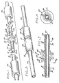
- the plastic gas pipe coupling includes, generally, a plastic fitting 21 which may be double ended and, in which case, includes a pair of axially spaced apart circular flanges 23 and 25, as well as oppositely extending spigots 27 and 29.
- the exterior of such spigots 27 and 29 are formed with frustoconically shaped annular sealing rings 31 and 33 which terminate at their enlarged ends in axially facing annular locking faces 35 and 37.
- Received telescopically within the fitting 21 is a metallic support tube, generally designated 41.
- Plastic finishing sleeves, generally designated 43 and 45 are telescopically received on plastic pipes 47 and 49.
- the ends of such pipes may be inserted over the ends of the spigots 27 and 29 as shown in FIGS. 5 - 7 and the finishing sleeves 43 and 45 drawn into position to compress the walls of the respective plastic tubes 47 and 49 radially inwardly to cause the plastic at the interior cold flow radially inwardly to fill the grooves formed between the respective locking rings 31 and 33 as shown in FIG. 7.
- the coupling of the present invention may be employed to couple a plastic pipe to any device which might incorporate a spigot
- the preferred embodiment disclosed here contemplates joining a pair of pipe sections together.
- FIG. 1 the occasion frequently arises where polyethelene pipes 47 and 49 on the order of 1 - 1/8 inch (28.6 mm) outside diameter (OD) and 7/8 inch (22.2 mm) inside diameter (ID) are to be coupled together.
- OD outside diameter
- ID inside diameter
- heat sources and related facilities are not readily available for conveniently fusing the pipe sections together. Consequently, there exists a demand for a plastic coupling apparatus which may be conveniently utilized by relatively unskilled personnel to join the pipe sections 47 and 49 together.
- a plastic fitting 21 which is somewhat tubular in configuration and is double ended to form the two oppositely directed spigots 27 and 29, one being the mirror image of the other.
- the fitting 21 is constructed of a high impact plastic such as a polyester resin sold by General Electric company under the designation Xenoy 6620.
- the flanges 23 and 25 are somewhat spool shaped to form therebetween a reduced in diameter tool access groove 55.
- the spigots 27 and 29 are formed on the distal extremities with stress relief nipples, 57 and 59, respectively, terminating in respective ends 58 and 60 and having a diameter of 0.430 inches (10.9 mm) to thus slip fit into the open of the pipes 47 and 49.
- the frusto-conical sealing rings 31 and 33 taper radially outwardly from a minor diameter to a major diameter of about 0.490 inches (12.4 mm) to thereby cooperate together in forming an overall configuration sufficient to, when the spigot 27 is inserted, expand the pipe 47 radially outwardly to an expanded bell-like configuration as shown in FIG. 5.
- the spigots are formed at their proximate ends with respective centering lands 61 and 65 having respective diameters of about .630 inches (16.0 mm) to slip fit into the interior diameters of the respective finishing sleeves 43 and 45.
- the metallic support tube 41 is preferably constructed of aluminum having a 5/16 inch (7.9 mm) OD and 0.028 inch (0.7 mm) wall thickness to thereby provide sufficient structural stiffness to withstand the compressive forces applied to the spigots 27 and 29.
- the tube 41 is press fit into a longitudinal bore formed in the fitting 21.
- finishing sleeves 43 and 45 are also preferably formed of high impact plastic, such as polyester sold by General Electric under the trademark Xenoy 6620 and have inside diameters which are sufficiently small to cooperate with the outside contour of the spigots as defined by the sealing rings 33 to form an annulus having a radial dimension which is sufficiently small to compress therein the walls of the tubes 47 and 49 as depicted in FIG. 7 to form a positive mechanical lock and gas impermeable seal.
- high impact plastic such as polyester sold by General Electric under the trademark Xenoy 6620 and have inside diameters which are sufficiently small to cooperate with the outside contour of the spigots as defined by the sealing rings 33 to form an annulus having a radial dimension which is sufficiently small to compress therein the walls of the tubes 47 and 49 as depicted in FIG. 7 to form a positive mechanical lock and gas impermeable seal.
- a convenient device for installing the coupling of the present invention is a clamping element having one pair of forks which may have its tines 75 inserted in straddling relationship into the tool-receiving groove 55 of the fitting 21 (FIG. 5).
- a second fork having its tines 77 inserted in straddling relationship over the pipe 47 and such forks then drawn axially together to urge the sleeve 43 onto the expanded section of the pipe 47 surrounding the spigot 27.
- the radius 71 of the leading end thereof will facilitate compression of the pipe wall, as well as travel therealong, until such time as it registers with the centering shoulder 61.
- the second pipe 49 may be brought into position as shown in FIG. 6 telescoped over the spigot 29 in a manner similar to that described hereinabove with respect to the pipe 47.
- the sleeve 45 may then be drawn into position to mechanically lock the pipe 49 positively onto the spigot 29 to hold such pipe securely coupled to and centered with respect to the fitting 21 and consequently the pipe 47.
- the corrugations formed in the interior wall thereof and about the sealing rings 31 and 33 will effect a positive seal against seepage and will positively prevent disjoinder of the pipes in the event axial or lateral stress forces are applied thereto.
- the coupling has proven to be more than effective in meeting the minimum requirements of the U. S. Department of Transportation Code Section 192 283 for mechanical couplings. While this DOT requires a tensile elongation pull of 0.2 inches per minute (0.08 mm/S), the subject coupling has been tested successfully at pull rates of between 10 and 30 inches per minute (4.2 and 12.7 mm/S).
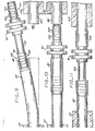
- the coupling, generally designed 80, shown in FIG. 8 is similar to that shown in FIGS. 1 - 7 except that the crowns 82 of the sealing rings 84 at the major diameter thereof have been flattened to form a blunt tooth arrangement as viewed in cross-section.
- Such flattening of the crowns 82 has proven necessary in some of the larger diameter couplings, the outer diameters of the rings 82 from bending back under the stress of the coupled pipe being drawn in a pull test thereby resulting in the rings 82 loosing their gripping effect in holding the pipe secured to the coupling.
- This flattening of the crowns of the sealing teeth is particularly important for coup- ings which are intended to be employed to repair a damaged pipe already in place as described hereinafter with respect to FIGS. 9 - 12.
- the method of repair disclosed contemplates one spigot of the fitting being inserted deep into one pipe end, the other spigot aligned with the other pipe end and the fitting then drawn toward such other pipe end thus necessitating partial withdrawal of the spigot from the first pipe end.
- the force required to overcome the resistance which such sharp rings present to such withdrawal is so great that the tensile strength of the pipe will be overcome before withdrawal is achieved thus resulting in elongation of the pipe.
- the coupling of the present invention is particularly adaptable to repairing an underground pipe which has been damaged and a section removed therefrom to leave two confronting, axially spaced apart pipe sections 81 and 85 terminating in ends 82 and 83, respectively.
- leaks in underground plastic gas pipes had posed a serious problem since plastic pipes cannot be easily threaded and connected together in a leak free manner by threaded couplings.
- Fittings incorporating spigots formed with circumferential rings having rounded, square or trapezoidal cross-sections had proven totally inadequate to serve as a coupling to join the ends of damaged plastic pipe.
- a repair coupling embodying the present invention it is possible to shut off the flow of, for instance, natural gas upstream of the leak, excavate in the area of the leak to expose the leaking pipe.
- the section in which the leak has occurred may then be simply removed by severing the pipe on both axial sides thereof to leave the exposed ends 82 and 83 disposed in confronting relationship spaced, for instance, three inches (76.2 mm) apart.
- the repair coupling generally designated 91 is formed with a pair of spaced apart flanges 90 and 92 which define therebetween a deep groove 94.
- a spigot section 95 Projecting in one axial direction from the flange 90 is an elongated tube section 93 which mounts a spigot section 95 on the remote end thereof.
- the spigot section 95 is formed on its periphery with axially spaced apart frusto-conical sealing rings 97 which terminate at the enlarged ends thereof in radial locking faces 99.
- the opposite end of the fitting 91 is formed with a similar spigot section, generally designated 101, which includes the frusto-conical sealing rings 103 terminating at the enlarged ends thereof in radial locking faces 105.
- a damaged polyethelene pipe may be excavated along a, for instance, five foot length (1.5 mm), and the leak resulting from such damage located.
- the section of pipe, for instance 3 inches (76.2 mm) in length, in which such leak is located may then be removed.
- Such remowal will leave the pipe sections 81 and 85 terminating in the confronting spaced apart ends 82 and 83.
- the repair coupling 91 has been found particularly effective in then joining the free ends 82 and 83 of the axially aligned pipe sections 81 and 85 thus accomplishing repair of the leak without expensive remowal of the entire pipe system or undertaking excessive excavation efforts along long lengths of the pipe.
- the insertion of the repair coupling 91 is similar to that described hereinabove with respect to FIGS. 1 - 7.
- the sleeves 111 and 113 are telescoped into the pipe sections 81 and 85 and the free end 82 of the section 81 deflected laterally to receive in the end thereof the spigot 95 formed on the end of the tube 93.
- the spigot section 95 is inserted in the pipe section 81 as shown in FIG. 8.
- This insertion may be achieved by utilizing a tool similar to that described with respect to FIGS. 5 and 6.
- One such tool which has been found satisfactory for this task is one sold under the trademark HYDROPRESS by R. W. Lyall & Company, Inc., 9837 Pioneer Boulevard, Santa Fe Springs, California.
- Such tool may include a vice like body having a lead screw or hydraulic piston (not shown) for drawing a clamp and a fork toward one another.
- the fork may be fitted in the groove 94 between the flanges 90 and 92 and the clamp clamped to the pipe 81 at a location spaced from the extremity thereof.
- the hydraulic cylinder may then be activated to draw the clamp and fork together thus driving the spigot 95 into the end of such tube 81 until it reaches the position shown in FIG. 9. It will be appreciated that as the spigot 95 is driven into the pipe section 81 the wall of such section will be expanded radially outwardly to a diameter dictated by the diameter of such spigot and the wall thickness of the pipe 81.
- the pipe section 81 may be flexed into axial realigned with the pipe section 85 as shown in FIG. 10.
- the tool may then be reversed to reverse the fork in the groove 94 and to clamp the tube 85 at a location spaced a sufficient distance from the end thereof so as not to interfere with expansion of the tube as the spigot 101 enters rotation of tube lead screw or actuation of the hydraulic pump will then serve to draw the clamp and fork together thus drawing the spigot 101 into the end of the pipe 85 while overcoming the retention forces tending to resist withdrawal of the spigot 95 to draw it sufficiently from the pipe section 81 to reach the position shown in FIG.
- the finishing sleeves 111 and 113 may then be drawn axially toward the repair fitting 91 to position such sleeves in surrounding relationship on the respective spigots 95 and 101 to compress the wall of the respective plastic pipe sections 81 and 85 radially inwardly into sealing engagement with the respective sealing rings 97 and 103 as described above in connection with FIGS. 1 - 8. Consequently, such repair coupling 91 provides an economical and efficient means for repairing a damaged plastic pipe in a secure and reliable manner.
- the plastic pipe coupling of the present invention provides a straight forward method for coupling plastic pipes together.
- the coupling may be installed in a short period of time by relatively unskilled personnel and requires only relatively inexpensive and uncomplicated clamping tools which are readily available and convenient to operate.
- the saw tooth shape of the ribs and grooves, as viewed in cross-section, forming the exterior of the spigots act as barbs to cooperate with the body of the mating pipe sections, as flowed thereabout by the compression of the finishing sleeve, to form a mechanical connection having a high degree of integrity and capable of withstanding high tensile and bending forces.
Landscapes
- Engineering & Computer Science (AREA)
- General Engineering & Computer Science (AREA)
- Mechanical Engineering (AREA)
- Joints With Sleeves (AREA)
- Rigid Pipes And Flexible Pipes (AREA)
Claims (10)
Applications Claiming Priority (2)
| Application Number | Priority Date | Filing Date | Title |
|---|---|---|---|
| US06/732,932 US4635972A (en) | 1985-05-13 | 1985-05-13 | Plastic pipe coupling apparatus and method of using same |
| US732932 | 1985-05-13 |
Publications (2)
| Publication Number | Publication Date |
|---|---|
| EP0204445A1 EP0204445A1 (de) | 1986-12-10 |
| EP0204445B1 true EP0204445B1 (de) | 1989-08-23 |
Family
ID=24945507
Family Applications (1)
| Application Number | Title | Priority Date | Filing Date |
|---|---|---|---|
| EP86303639A Expired EP0204445B1 (de) | 1985-05-13 | 1986-05-13 | Kunststoffrohrkupplungsapparat und Methode zu seiner Verwendung |
Country Status (3)
| Country | Link |
|---|---|
| US (1) | US4635972A (de) |
| EP (1) | EP0204445B1 (de) |
| ES (1) | ES8708045A1 (de) |
Families Citing this family (99)
| Publication number | Priority date | Publication date | Assignee | Title |
|---|---|---|---|---|
| USD290646S (en) | 1985-01-11 | 1987-06-30 | Cook Donald W | Hose splicer |
| US4918877A (en) * | 1988-12-08 | 1990-04-24 | Dutka Walter J | Inflatable tubular structure |
| US4997214A (en) * | 1988-12-08 | 1991-03-05 | Dresser Industries, Inc. | Transition fitting |
| BE1002947A3 (nl) * | 1989-03-17 | 1991-09-17 | Jonaco G M B H | Kunststofkoppelstuk. |
| USD333178S (en) | 1990-05-31 | 1993-02-09 | Wirthco Engineering, Inc. | Hose coupler |
| US5090745A (en) * | 1990-08-23 | 1992-02-25 | Itt Corporation | Quick-connect connector for plastic tubes |
| US5735554A (en) * | 1991-08-31 | 1998-04-07 | Imgam; Fredrich | Tube conduit connection and method of producing the same from polyolefins |
| US5211429A (en) * | 1991-09-09 | 1993-05-18 | Charlson Norman E | Polyethylene pipe junction device |
| US5326137A (en) * | 1991-09-24 | 1994-07-05 | Perfection Corporation | Gas riser apparatus and method |
| AU3721693A (en) * | 1992-02-18 | 1993-09-13 | Huron Products, Inc. | Ring clamp for securing a hose to a barbed fitting |
| US5299842A (en) * | 1992-07-24 | 1994-04-05 | Micron Technology, Inc. | Fluid line clamp |
| US5222768A (en) * | 1992-07-31 | 1993-06-29 | Micron Technology, Inc. | Fluid line nut locking device |
| US5937501A (en) * | 1993-03-27 | 1999-08-17 | Imgram; Friedrich | Process for making tube conduit connections |
| US5367756A (en) * | 1993-12-07 | 1994-11-29 | R. W. Lyall & Company, Inc. | Gas meter riser transition field completion tool |
| DE9402909U1 (de) * | 1994-02-22 | 1994-08-04 | Thermconcept Produkte für Heizung und Sanitär GmbH & Co., 48282 Emsdetten | Zweiteiliger Klemmverbinder |
| WO1995028594A1 (en) * | 1994-04-13 | 1995-10-26 | Mallinckrodt Medical, Inc. | Connector for tubing |
| FR2726345B1 (fr) | 1994-11-02 | 1996-12-27 | Atochem Elf Sa | Tubes en polyamide et en polyethylene pour la distribution du gaz domestique |
| FR2728050B1 (fr) * | 1994-12-12 | 1998-01-09 | Rw Lyall & Company | Accouplement mecanique pour le raccordement de tubes en polyethylene |
| US5573280A (en) * | 1995-02-28 | 1996-11-12 | Salter Labs | Tubing end-piece and connector |
| US5797627A (en) * | 1995-02-28 | 1998-08-25 | Salter Labs | Swivel |
| US5622394A (en) * | 1995-03-15 | 1997-04-22 | Bundy Corporation | Corrosion-resistant joint |
| US5556136A (en) * | 1995-04-25 | 1996-09-17 | Von Berg; Peter | Connector for flexible medical tubing |
| US5772261A (en) * | 1995-07-21 | 1998-06-30 | The Nemours Foundation | Cannula connector and method of connecting medical tubes |
| US5913852A (en) * | 1995-07-21 | 1999-06-22 | Nemours Foundation | Drain cannula |
| DE19707827C2 (de) * | 1997-02-25 | 1999-04-01 | Geberit Technik Ag | Pressverbindung |
| US6447020B1 (en) | 1998-03-24 | 2002-09-10 | C. F. Gomma Usa, Inc. | High-pressure integral tube coupling arrangements |
| JP4233148B2 (ja) * | 1998-06-05 | 2009-03-04 | 臼井国際産業株式会社 | 樹脂製の細径配管接続用コネクター |
| US6142538A (en) * | 1998-07-28 | 2000-11-07 | Perfection Corporation | Stab-type coupling with conduit inner diameter seal |
| US6270125B1 (en) * | 1999-10-06 | 2001-08-07 | Mercury Plastics, Inc. | Molded tubing assemblies |
| NO20001606L (no) * | 2000-03-28 | 2001-10-01 | Nexans | Skjöt i offshore umbilikalslange |
| US6641177B1 (en) | 2000-08-25 | 2003-11-04 | Precision Design Concepts, Llc | Quick connect tube coupling and method of assembling the same |
| US6502321B1 (en) | 2000-08-25 | 2003-01-07 | Crain Enterprises, Inc. | Pole section for surveying equipment |
| US6688012B1 (en) * | 2000-08-25 | 2004-02-10 | Crain Enterprises, Inc. | Surveying pole with telescoping sections |
| US6772526B1 (en) | 2000-08-25 | 2004-08-10 | Crain Enterprises, Inc. | Surveying pole |
| SE519817C2 (sv) * | 2000-09-29 | 2003-04-15 | Scania Cv Ab | Förstärkningsanordning vid rörgenomföring |
| US6530574B1 (en) | 2000-10-06 | 2003-03-11 | Gary L. Bailey | Method and apparatus for expansion sealing concentric tubular structures |
| IT1319088B1 (it) * | 2000-11-08 | 2003-09-23 | Alfagomma S P A | Raccordo per tubi rivestiti internamente e procedimento per la suamessa in opera |
| DE60235410D1 (de) * | 2002-01-07 | 2010-04-01 | Enventure Global Technology | Schutzhülse für gewindeverbindungen für eine ausdehnbare liner-aufhängvorrichtung |
| EP1501644B1 (de) | 2002-04-12 | 2010-11-10 | Enventure Global Technology | Schutzhülse für gewindeverbindungen für ausdehnbare liner-hänger |
| EP1501645A4 (de) * | 2002-04-15 | 2006-04-26 | Enventure Global Technology | Schutzhülse für gewindeverbindungen für ausdehnbare liner-hänger |
| US20070152442A1 (en) * | 2002-06-13 | 2007-07-05 | Dayco Products, Llc | Brazeless connector for fluid transfer assemblies |
| US7185921B2 (en) * | 2002-06-28 | 2007-03-06 | Nestec S.A. | Hose fitment for disposable food container |
| DE10233968C1 (de) * | 2002-07-25 | 2003-12-18 | Uponor Innovation Ab | Presshülsenbeschichtung |
| US6846124B2 (en) | 2002-10-04 | 2005-01-25 | Stephen Warburton-Pitt | Collar for a barbed connector |
| US20040211320A1 (en) * | 2003-04-22 | 2004-10-28 | Cain Rodney H. | Integration of a metallic substrate into a plastic induction system |
| CA2530829C (en) * | 2003-08-21 | 2012-03-20 | Steven Slunick | Metal to plastic fluid connection with overmolded anti-rotation retainer |
| US7331613B2 (en) * | 2004-05-13 | 2008-02-19 | Medtronic, Inc. | Medical tubing connector assembly incorporating strain relief sleeve |
| KR100609868B1 (ko) | 2005-05-02 | 2006-08-22 | 주식회사 평온하이텍 | 니플과 이 니플이 채택된 열전달파이프 조립체 |
| US7448653B2 (en) * | 2005-06-10 | 2008-11-11 | Value Plastics, Inc. | Female connector for releasable coupling with a male connector defining a fluid conduit |
| US7806139B2 (en) * | 2006-01-20 | 2010-10-05 | Value Plastics, Inc. | Fluid conduit coupling assembly having male and female couplers with integral valves |
| US20070176413A1 (en) * | 2006-01-27 | 2007-08-02 | Central Plastics Company | Corrosion resistant gas service riser assembly |
| US7690692B2 (en) * | 2006-08-21 | 2010-04-06 | Continental Automotive Systems Us, Inc. | Electrostatic discharge solution for angled fuel port of a fuel pump |
| US20080078732A1 (en) * | 2006-09-28 | 2008-04-03 | Junior Julian Hsu | Screwless metal hinge and rack |
| US20080221469A1 (en) * | 2007-03-08 | 2008-09-11 | George John Shevchuk | Fitting and fluid-conveying device connected thereto |
| US20080275427A1 (en) * | 2007-05-01 | 2008-11-06 | Sage Shahn S | Threaded catheter connector, system, and method |
| US8512312B2 (en) * | 2007-05-01 | 2013-08-20 | Medtronic, Inc. | Offset catheter connector, system and method |
| USD654573S1 (en) | 2007-11-19 | 2012-02-21 | Value Plastics, Inc. | Female quick connect fitting |
| US8235426B2 (en) | 2008-07-03 | 2012-08-07 | Nordson Corporation | Latch assembly for joining two conduits |
| US8091928B2 (en) * | 2009-02-26 | 2012-01-10 | Eaton Corporation | Coupling assembly for connection to a hose |
| US9371921B2 (en) * | 2009-06-23 | 2016-06-21 | Nordson Corporation | Multi-port valve |
| USD655393S1 (en) | 2009-06-23 | 2012-03-06 | Value Plastics, Inc. | Multi-port valve |
| DE102009038132B4 (de) * | 2009-08-12 | 2015-12-24 | Joma-Polytec Gmbh | Vakuumpumpe |
| USD650478S1 (en) | 2009-12-23 | 2011-12-13 | Value Plastics, Inc. | Female dual lumen connector |
| USD649240S1 (en) | 2009-12-09 | 2011-11-22 | Value Plastics, Inc. | Male dual lumen bayonet connector |
| USD783815S1 (en) | 2009-12-09 | 2017-04-11 | General Electric Company | Male dual lumen bayonet connector |
| US9388929B2 (en) | 2009-12-09 | 2016-07-12 | Nordson Corporation | Male bayonet connector |
| US10711930B2 (en) | 2009-12-09 | 2020-07-14 | Nordson Corporation | Releasable connection assembly |
| US9046205B2 (en) * | 2009-12-09 | 2015-06-02 | Nordson Corporation | Fluid connector latches with profile lead-ins |
| US9440250B2 (en) | 2009-12-18 | 2016-09-13 | Rain Bird Corporation | Pop-up irrigation device for use with low-pressure irrigation systems |
| US8950789B2 (en) | 2009-12-18 | 2015-02-10 | Rain Bird Corporation | Barbed connection for use with irrigation tubing |
| EP2516914B1 (de) | 2009-12-23 | 2018-09-05 | General Electric Company | Knopfverriegelung mit einteilig geformten cantileverfedern |
| MX353638B (es) | 2010-04-23 | 2018-01-22 | Medical Components Inc | Puerto de acceso implantable con depósito doble. |
| CN101829706B (zh) * | 2010-04-30 | 2011-11-09 | 浙江广涛卫厨有限公司 | 一种快速连接管的生产工艺 |
| EP2481966A1 (de) * | 2011-02-01 | 2012-08-01 | Uponor Innovation AB | Klemmring |
| USD652511S1 (en) | 2011-02-11 | 2012-01-17 | Value Plastics, Inc. | Female body of connector for fluid tubing |
| USD663022S1 (en) | 2011-02-11 | 2012-07-03 | Nordson Corporation | Male body of connector for fluid tubing |
| USD652510S1 (en) | 2011-02-11 | 2012-01-17 | Value Plastics, Inc. | Connector for fluid tubing |
| US8898876B2 (en) | 2011-03-30 | 2014-12-02 | Rain Bird Corporation | Barbed fittings, fitting insertion tools and methods relating to same |
| USD699840S1 (en) | 2011-07-29 | 2014-02-18 | Nordson Corporation | Male body of connector for fluid tubing |
| USD699841S1 (en) | 2011-07-29 | 2014-02-18 | Nordson Corporation | Female body of connector for fluid tubing |
| USD698440S1 (en) | 2011-07-29 | 2014-01-28 | Nordson Corporation | Connector for fluid tubing |
| RU2478884C1 (ru) * | 2011-09-26 | 2013-04-10 | Павел Эдуардович Мельников | Секционный радиатор водяного отопления и футорка для него |
| USD709612S1 (en) | 2011-12-23 | 2014-07-22 | Nordson Corporation | Female dual lumen connector |
| US8668231B1 (en) | 2013-01-28 | 2014-03-11 | Sidney T. Fails | Pipe repair coupling |
| US9482375B2 (en) * | 2013-03-07 | 2016-11-01 | Zbigniew Robert Paul | Hose connector assembly for coupling pressurized hoses |
| US20140291982A1 (en) * | 2013-03-29 | 2014-10-02 | Superior Fit, Llc | Pipe coupling |
| NL2010725C2 (en) * | 2013-04-26 | 2014-10-29 | Dejatech Ges B V | Modular heat exchanger with sections interconnected by connectors. |
| US20170002556A1 (en) * | 2015-06-30 | 2017-01-05 | Dennis Lowell Lukes | Magic Water Saver |
| DE102015113626B4 (de) * | 2015-08-18 | 2019-05-29 | Norma Germany Gmbh | Verbindungsanordnung und Pressring für eine Verbindungsanordnung |
| CN105114736B (zh) * | 2015-09-18 | 2017-12-29 | 苏州益诺斯医疗科技有限公司 | 一种医用气管接口及其安装方法 |
| DE202015106955U1 (de) * | 2015-12-21 | 2017-03-22 | Rehau Ag + Co | Rohrverbindung |
| DE202015106954U1 (de) * | 2015-12-21 | 2017-03-22 | Rehau Ag + Co | Verbindungselement sowie dieses umfassende Rohrverbindung |
| DE202015106953U1 (de) * | 2015-12-21 | 2017-03-22 | Rehau Ag + Co | Schiebehülsenverbindung |
| USD838366S1 (en) | 2016-10-31 | 2019-01-15 | Nordson Corporation | Blood pressure connector |
| CN107401647A (zh) * | 2017-08-15 | 2017-11-28 | 日丰企业(佛山)有限公司 | 管件连接方法及连接结构 |
| US11060652B2 (en) | 2017-12-22 | 2021-07-13 | ASC Engineered Solutions, LLC | Malleable press fittings |
| CN108355198B (zh) * | 2018-03-06 | 2024-02-13 | 程基才 | 一种无钢针输液系统 |
| AU2019339784B2 (en) * | 2018-09-11 | 2024-12-19 | Netafim Ltd | Corrugated piping assembly and sleeve for same |
| US12104728B1 (en) | 2023-11-28 | 2024-10-01 | Cabriolet Hydraulics, LLC | Pivotable hose connector and hydraulic cylinder having a pivotable hose suitable for use in association with convertible tops |
Family Cites Families (16)
| Publication number | Priority date | Publication date | Assignee | Title |
|---|---|---|---|---|
| GB138791A (en) * | 1919-05-20 | 1920-02-19 | Frederick Braby And Company Lt | Improvements in interception valves for acetylene welding plants |
| US2319024A (en) * | 1941-06-26 | 1943-05-11 | Herman H Wehringer | Hose coupling |
| NL94577C (de) * | 1953-05-26 | 1900-01-01 | ||
| DE921006C (de) * | 1953-11-03 | 1954-12-06 | Pleiger Paul | Schlauchverschraubung |
| GB1596112A (en) * | 1978-03-31 | 1981-08-19 | British Gas Corp | Pipe coupling and a method for assembling the coupling |
| GB808984A (en) * | 1956-02-21 | 1959-02-18 | Stewarts & Lloyds Ltd | Pipe joints |
| GB903757A (en) * | 1960-06-13 | 1962-08-22 | Montedison Spa | Method of joining a pipe |
| US3315986A (en) * | 1964-05-05 | 1967-04-25 | Carl F Quick | Means and methods for connecting tubular conduits |
| US3408099A (en) * | 1968-02-05 | 1968-10-29 | Appleton Electric Co | Connector for flexible hosing |
| FR2064458A1 (de) * | 1969-10-21 | 1971-07-23 | Allied Chem | |
| GB1310367A (en) * | 1970-09-15 | 1973-03-21 | Martonair Ltd | Pipe coupling |
| US3826521A (en) * | 1972-10-30 | 1974-07-30 | P Wilhelmsen | Glued replacement unit for repairing ruptured pipe |
| US4231596A (en) * | 1978-03-17 | 1980-11-04 | Ridenour Ralph Gaylord | Tubing joint assembly |
| US4392678A (en) * | 1979-06-18 | 1983-07-12 | Titeflex Corporation | End fittings for flexible hoses |
| AU8853682A (en) * | 1982-09-23 | 1984-03-29 | Picton, D.J. | Pipe connector |
| US4489961A (en) * | 1983-04-18 | 1984-12-25 | The Singer Company | Terminal for flexible tube |
-
1985
- 1985-05-13 US US06/732,932 patent/US4635972A/en not_active Expired - Lifetime
-
1986
- 1986-05-13 ES ES554931A patent/ES8708045A1/es not_active Expired
- 1986-05-13 EP EP86303639A patent/EP0204445B1/de not_active Expired
Also Published As
| Publication number | Publication date |
|---|---|
| ES554931A0 (es) | 1987-09-01 |
| US4635972A (en) | 1987-01-13 |
| ES8708045A1 (es) | 1987-09-01 |
| EP0204445A1 (de) | 1986-12-10 |
Similar Documents
| Publication | Publication Date | Title |
|---|---|---|
| EP0204445B1 (de) | Kunststoffrohrkupplungsapparat und Methode zu seiner Verwendung | |
| EP1141607B1 (de) | Rohrverbindung | |
| CA1064546A (en) | Coupling for plastic pipe | |
| EP1039203B1 (de) | Rohrverbindung | |
| CA2001061C (en) | Abrasive grip pipe coupling | |
| US5145216A (en) | Pipe connection assembly | |
| US5967568A (en) | Plastic pipe adaptor for a mechanical joint | |
| US6499772B1 (en) | Radial conduit coupling system and method | |
| US20090152863A1 (en) | Restrained pipe joining system for plastic pipe | |
| HU209196B (en) | Joint of tubes and pipe unions and method for forming the joint | |
| WO1995033948A1 (en) | Mechanical joint pipe adapter | |
| US4769892A (en) | Pipe joining method | |
| LU101005B1 (en) | Positive Lock system for Restrained Joints of Ductile Iron Spun Pipes and Fittings | |
| EP0044719A1 (de) | Vorrichtung zum Abdichten von Rohren | |
| EP1040293B1 (de) | Verbindung für kunststoffrohre | |
| WO2004046603A1 (en) | Improved pipe connector | |
| CN121676807A (zh) | 一种金属管件环形压接结构 | |
| AU2003101082A4 (en) | Improved pipe connector | |
| CA1314243C (en) | Plastic pipe with locking integral end connection | |
| EP0222719A1 (de) | Eine Verbindungseinrichtung zur abdichtenden Verbindung rohrförmiger Elemente | |
| WO2019239298A1 (en) | Trenchless mechanical lining apparatus for continuous repair of underground pipes and culverts, and method of installation | |
| MXPA98004715A (es) | Adaptador para tubo plastico tal como para una junta mecanica | |
| EP0192698A1 (de) | Leitungskupplung, insbesondere für kunststoffschläuche | |
| AU2003283056A1 (en) | Improved pipe connector | |
| MXPA97002374A (en) | Coupling assembly that has resistance to increased axial latension and method of installation of the underground duct acopl |
Legal Events
| Date | Code | Title | Description |
|---|---|---|---|
| PUAI | Public reference made under article 153(3) epc to a published international application that has entered the european phase |
Free format text: ORIGINAL CODE: 0009012 |
|
| AK | Designated contracting states |
Kind code of ref document: A1 Designated state(s): BE CH GB LI |
|
| 17P | Request for examination filed |
Effective date: 19870609 |
|
| 17Q | First examination report despatched |
Effective date: 19880505 |
|
| GRAA | (expected) grant |
Free format text: ORIGINAL CODE: 0009210 |
|
| AK | Designated contracting states |
Kind code of ref document: B1 Designated state(s): BE CH GB LI |
|
| PLBE | No opposition filed within time limit |
Free format text: ORIGINAL CODE: 0009261 |
|
| STAA | Information on the status of an ep patent application or granted ep patent |
Free format text: STATUS: NO OPPOSITION FILED WITHIN TIME LIMIT |
|
| 26N | No opposition filed | ||
| PGFP | Annual fee paid to national office [announced via postgrant information from national office to epo] |
Ref country code: GB Payment date: 20000505 Year of fee payment: 15 |
|
| PGFP | Annual fee paid to national office [announced via postgrant information from national office to epo] |
Ref country code: CH Payment date: 20000530 Year of fee payment: 15 |
|
| PGFP | Annual fee paid to national office [announced via postgrant information from national office to epo] |
Ref country code: BE Payment date: 20000614 Year of fee payment: 15 |
|
| PG25 | Lapsed in a contracting state [announced via postgrant information from national office to epo] |
Ref country code: GB Free format text: LAPSE BECAUSE OF NON-PAYMENT OF DUE FEES Effective date: 20010513 |
|
| PG25 | Lapsed in a contracting state [announced via postgrant information from national office to epo] |
Ref country code: BE Free format text: LAPSE BECAUSE OF NON-PAYMENT OF DUE FEES Effective date: 20010531 |
|
| PG25 | Lapsed in a contracting state [announced via postgrant information from national office to epo] |
Ref country code: CH Free format text: LAPSE BECAUSE OF NON-PAYMENT OF DUE FEES Effective date: 20010612 Ref country code: LI Free format text: LAPSE BECAUSE OF NON-PAYMENT OF DUE FEES Effective date: 20010612 |
|
| BERE | Be: lapsed |
Owner name: R.W. LYALL & CY INC. Effective date: 20010531 |
|
| GBPC | Gb: european patent ceased through non-payment of renewal fee |
Effective date: 20010513 |
|
| REG | Reference to a national code |
Ref country code: CH Ref legal event code: PL |