EP0204033B1 - Strömungsmaschine - Google Patents
Strömungsmaschine Download PDFInfo
- Publication number
- EP0204033B1 EP0204033B1 EP85116447A EP85116447A EP0204033B1 EP 0204033 B1 EP0204033 B1 EP 0204033B1 EP 85116447 A EP85116447 A EP 85116447A EP 85116447 A EP85116447 A EP 85116447A EP 0204033 B1 EP0204033 B1 EP 0204033B1
- Authority
- EP
- European Patent Office
- Prior art keywords
- housing
- bearing
- turbo
- flow
- guide
- Prior art date
- Legal status (The legal status is an assumption and is not a legal conclusion. Google has not performed a legal analysis and makes no representation as to the accuracy of the status listed.)
- Expired
Links
- 239000012530 fluid Substances 0.000 description 5
- 239000000919 ceramic Substances 0.000 description 2
- 230000015572 biosynthetic process Effects 0.000 description 1
- 238000010276 construction Methods 0.000 description 1
- 230000001419 dependent effect Effects 0.000 description 1
- 238000003780 insertion Methods 0.000 description 1
- 230000037431 insertion Effects 0.000 description 1
- 238000009434 installation Methods 0.000 description 1
- 230000008646 thermal stress Effects 0.000 description 1
Images

Classifications
-
- F—MECHANICAL ENGINEERING; LIGHTING; HEATING; WEAPONS; BLASTING
- F01—MACHINES OR ENGINES IN GENERAL; ENGINE PLANTS IN GENERAL; STEAM ENGINES
- F01D—NON-POSITIVE DISPLACEMENT MACHINES OR ENGINES, e.g. STEAM TURBINES
- F01D17/00—Regulating or controlling by varying flow
- F01D17/10—Final actuators
- F01D17/12—Final actuators arranged in stator parts
- F01D17/14—Final actuators arranged in stator parts varying effective cross-sectional area of nozzles or guide conduits
- F01D17/16—Final actuators arranged in stator parts varying effective cross-sectional area of nozzles or guide conduits by means of nozzle vanes
- F01D17/165—Final actuators arranged in stator parts varying effective cross-sectional area of nozzles or guide conduits by means of nozzle vanes for radial flow, i.e. the vanes turning around axes which are essentially parallel to the rotor centre line
-
- F—MECHANICAL ENGINEERING; LIGHTING; HEATING; WEAPONS; BLASTING
- F01—MACHINES OR ENGINES IN GENERAL; ENGINE PLANTS IN GENERAL; STEAM ENGINES
- F01D—NON-POSITIVE DISPLACEMENT MACHINES OR ENGINES, e.g. STEAM TURBINES
- F01D9/00—Stators
- F01D9/02—Nozzles; Nozzle boxes; Stator blades; Guide conduits, e.g. individual nozzles
- F01D9/04—Nozzles; Nozzle boxes; Stator blades; Guide conduits, e.g. individual nozzles forming ring or sector
- F01D9/045—Nozzles; Nozzle boxes; Stator blades; Guide conduits, e.g. individual nozzles forming ring or sector for radial flow machines or engines
Definitions
- the invention relates to a turbomachine according to the preamble of claim 1, as is known for example from DE-A 23 33 525.
- Adjustable guide vanes are arranged in an annular channel of the turbine housing through which the fluid flows radially.
- the guide vanes are each provided on one narrow side with bearing journals, which are rotatably mounted in bearing bores in the ring channel wall adjacent to the bearing housing. Actuating lifts, which interact with an adjusting ring, engage the bearing journals.
- the gap width is particularly unfavorable in the construction shown, in which the tolerances of adjoining housing parts determine the ring channel width.
- the distance between the ring channel walls can vary between a minimum and a maximum value.
- the blade widths must be chosen smaller than the minimum width of the ring channel.
- the guide vanes lie with their narrow sides against the walls of the flow channel with the avoidance of gaps entirely.
- the flow channel in the area of the guide vanes is formed on one side by a wall disk which is axially resiliently supported by springs. Heat distortion does not lead to the guide vanes jamming because the axially flexible wall disc carries out corresponding compensating movements.
- the disadvantage of this design is the high structural complexity with a large variety of components. Due to the low stability of spring elements at high temperatures, their use in the hot gas area of turbines of exhaust gas turbochargers is not recommended.
- the invention has for its object to make the turbomachine structurally simple and reliable with respect to the bearing of the guide vanes and to improve the efficiency by reducing the gap losses.
- the guide vane carrier consisting of two wall rings, which are rigidly and non-detachably connected to one another via connecting webs, forms a separate component which represents a one-piece bearing cage with lateral flow surfaces for the guide vanes.
- the axial width of the space for the guide vanes on this structurally simple component can be machined very precisely, which means small gap widths and correspondingly improved efficiencies.
- the guide vane carrier is held on one side in the housing in such a way that warping of the bearing and flow housing as a result of heat and pressure is not transferred to the guide vane carrier and consequently such influences do not have to be taken into account when determining the gap widths.
- Fig. 1 is a longitudinal section through the turbine 1 of an exhaust gas turbocharger.
- the associated flow compressor connected to the turbine 1 via a common shaft 2 is not shown here.
- the flow housing is axially clamped against the bearing housing via a clamping ring screwed onto the flow housing.
- the shaft 2 is mounted in the bearing housing.
- Adjustable guide vanes 7 are arranged in an annular channel which extends radially and through which the fluid flows from the outside inwards.
- the guide vanes 7 are rotatably mounted in a guide vane carrier 8 on bearing journals 9 which engage in bearing bores 10 of an outer wall ring of the guide vane carrier 8 on the outer side of the fluid outlet and the inner side on the bearing housing.
- the wall rings are joined to the guide vane carrier via a number of connecting webs that lie in the flow.
- the connecting webs rigidly connect the wall rings to one another. For example, they are welded to the wall rings or otherwise permanently connected to the wall rings.
- the inner surfaces of the wall rings at least partially form the boundary or flow surfaces for the fluid flowing through the annular channel 6.
- the flow area in the region of the guide vanes is also partially formed by the adjusting ring 12, which is preferably provided with cams 11 projecting into the flow channel.
- the adjusting ring 12 also represents the lateral flow area in the region of the impeller blades.
- An annular flange 13 is also formed on the guide vane carrier 8, which is supported with its end face 14 on the bearing housing 3 and at the same time on an outer shoulder against that on the bearing housing 3 supported flow housing 5 is clamped.
- an axial expansion gap 16 can be provided between the outer wall ring and the housing recess, in which it is embedded, which permits axial expansion of the guide vane carrier 8.
- distortion of the housing is not transmitted with this one-sided clamping of the guide vane carrier on the ring flange.
- a section of a heat shield 17 is also clamped, which prevents excessive heat flow to the bearing housing 3 and represents the flow wall in the region of the impeller 18.
- An axially extending section of the adjusting ring 12 is axially but rotatably fixed between an inner shoulder of the ring flange 13 and the heat shield 17 supported on the bearing housing 3.
- an adjusting shaft 19 is arranged in the bearing housing 3, the rotations of which are transmitted to an actuating lever 10 which engages with an axial pin 21 in a tab 22 which is connected to the adjusting ring 12.
- the control shaft 19 is preferably mounted in a heat-insulating ceramic bush 23.
- the adjusting shaft 19 can, as is not shown, be axially clamped against the ceramic bushing by a spring.
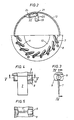
- FIG. 2 shows a cross-sectional view of the turbine 1 along the section line II-II drawn in FIG. 1.
- the pin 21 of the adjusting shaft 19 is shown, which engages in the tab 22, which is connected via a pin 24 to the radially retracted edge of the adjusting ring 12.
- the pin 24 engages in an elongated hole in the circumferential direction of the heat shield 17, as a result of which the adjustment path is limited.
- a radially outwardly oriented limiting pin connected to the adjusting ring engages in a limited recess in the ring flange of the guide vane carrier. The better heat shielding to the hot gas space is advantageous here, since there is no recess for the passage of the limiting pin.
- the adjusting ring 12 is shown with its cam-shaped elevations, which interact in the region of the guide vane ends with the guide vanes 7 for changing their position for different operating conditions of the exhaust gas turbocharger.
- the cam shape is streamlined, preferably in the form of blade profiles.
- 3 to 5 show the mounting of a guide vane in different views.
- FIG 3 shows a section in the area of the bearing through the wall ring of the guide vane carrier 8 on the side of the bearing housing transversely to the bearing journal 9.
- the bearing bore 10 in the region of the bearing journal connection has radial access of the width of the blade profile.
- the diameter of the bearing pin 9 is substantially larger than the blade width, so that despite the radial recess in the bearing bore a secure, tilt-free guidance of the bearing pin 9 is ensured.
- the bearing journals can differ Liche diameter or have different lengths. This means that an incorrect installation position when inserting into the guide vane carrier is excluded.
- FIG. 4 shows the view of the bearing along the section line IV-IV shown in FIG. 3.
- Fig. 5 shows the view of the storage along the section line V-V drawn in Fig. 4. 4 and 5 that the bearing bore 10 in the outer wall ring is only axially accessible.
- the guide vanes 7, which are provided with rigidly connected bearing pins 9, are introduced in a radial movement and in a subsequent axial movement in which the bearing pins 9 are inserted into the bearing bores 10.
- a profile section of the blade is located in the slot of the one bearing bore. It is also conceivable to make both bearing bores without slots. Then, however, the bearing journals cannot be made in one piece with the guide vanes, but must be designed to be attachable to the guide vanes.
- a component unit as it represents the guide vane carrier, can be machined before the insertion of the guide vanes to the exact dimensional accuracy of the space for the guide vanes in its axial width. This means that the gap losses are kept correspondingly small and thus efficiencies can be achieved which are cheaper than, however, when the guide vanes are appropriately supported between the housing walls or connected to the housing walls, however. not rigidly coupled wall rings. Furthermore, since the guide vane carrier can be arranged in the housing in such a way that warping of the housing as a result of pressure and thermal stresses is not transmitted to the guide vane carrier, the gap tolerances can be narrowed accordingly and the efficiency improved.
- turbine housing can be screwed onto the bearing housing in any rotational position without the guide vane position being changed thereby. This is important when mounting the exhaust gas turbocharger on different engines.
Landscapes
- Engineering & Computer Science (AREA)
- Mechanical Engineering (AREA)
- General Engineering & Computer Science (AREA)
- Supercharger (AREA)
- Control Of Turbines (AREA)
- Turbine Rotor Nozzle Sealing (AREA)
Applications Claiming Priority (2)
| Application Number | Priority Date | Filing Date | Title |
|---|---|---|---|
| DE19853516738 DE3516738A1 (de) | 1985-05-09 | 1985-05-09 | Stroemungsmaschine |
| DE3516738 | 1985-05-09 |
Publications (2)
| Publication Number | Publication Date |
|---|---|
| EP0204033A1 EP0204033A1 (de) | 1986-12-10 |
| EP0204033B1 true EP0204033B1 (de) | 1988-06-15 |
Family
ID=6270288
Family Applications (1)
| Application Number | Title | Priority Date | Filing Date |
|---|---|---|---|
| EP85116447A Expired EP0204033B1 (de) | 1985-05-09 | 1985-12-21 | Strömungsmaschine |
Country Status (4)
| Country | Link |
|---|---|
| US (1) | US4702672A (https=) |
| EP (1) | EP0204033B1 (https=) |
| JP (1) | JPS61258903A (https=) |
| DE (1) | DE3516738A1 (https=) |
Cited By (1)
| Publication number | Priority date | Publication date | Assignee | Title |
|---|---|---|---|---|
| US9057280B2 (en) | 2012-01-31 | 2015-06-16 | Honeywell International Inc. | Contacting vanes |
Families Citing this family (34)
| Publication number | Priority date | Publication date | Assignee | Title |
|---|---|---|---|---|
| DE3541508C1 (de) * | 1985-11-23 | 1987-02-05 | Kuehnle Kopp Kausch Ag | Abgasturbolader |
| US4804316A (en) * | 1985-12-11 | 1989-02-14 | Allied-Signal Inc. | Suspension for the pivoting vane actuation mechanism of a variable nozzle turbocharger |
| US4880351A (en) * | 1986-05-30 | 1989-11-14 | Honda Giken Kogyo Kabushiki Kaisha | Variable capacity turbine |
| US4907952A (en) * | 1986-12-05 | 1990-03-13 | Honda Giken Kogyo Kabushiki Kaisha | Turbocharger |
| JPS63183207A (ja) * | 1987-01-23 | 1988-07-28 | Honda Motor Co Ltd | 可変容量式タ−ビン |
| JPH01227823A (ja) * | 1988-03-08 | 1989-09-12 | Honda Motor Co Ltd | タービンの可変ノズル構造 |
| JP2001289050A (ja) * | 1999-05-20 | 2001-10-19 | Hitachi Ltd | 可変容量ターボ過給機 |
| US6453556B1 (en) * | 2000-10-11 | 2002-09-24 | Hmy Ltd. | Method of producing exhaust gas vane blade for superchargers of motor vehicles and vane blade |
| AU2002235452A1 (en) * | 2001-01-25 | 2002-08-06 | Honeywell International Inc. | Actuator shaft seal for variable nozzle turbocharger |
| EP1394364B1 (de) * | 2002-08-26 | 2006-03-08 | BorgWarner Inc. | Turbolader und Schaufellagerring hierfür |
| FR2845731B1 (fr) * | 2002-10-14 | 2005-01-28 | Renault Sa | Turbocompresseur a insert double jeu pour vehicule automobile |
| DE10256418A1 (de) * | 2002-12-02 | 2004-06-09 | Abb Turbo Systems Ag | Abgasturbinengehäuse |
| DE50304673D1 (de) * | 2003-10-27 | 2006-09-28 | Borgwarner Inc | Strömungsmaschine und Verfahren zum Herstellen eines Leitgitters |
| US7147433B2 (en) * | 2003-11-19 | 2006-12-12 | Honeywell International, Inc. | Profiled blades for turbocharger turbines, compressors, and the like |
| US7322805B2 (en) * | 2004-01-30 | 2008-01-29 | Itt Manufacturing Enterprises, Inc. | Impeller adjustment device and method for doing the same for close coupled pumps |
| US6925806B1 (en) * | 2004-04-21 | 2005-08-09 | Honeywell International, Inc. | Variable geometry assembly for turbochargers |
| EP1672177B1 (de) * | 2004-12-14 | 2011-11-23 | BorgWarner, Inc. | Turbolader |
| EP1676980B1 (de) * | 2004-12-28 | 2015-10-14 | BorgWarner, Inc. | Turbolader mit variabler Turbinengeometrie |
| EP1722073B1 (de) * | 2005-05-13 | 2013-01-23 | BorgWarner, Inc. | Verstellring zum Verstellen der Schaufeln des VTG-Leitapparates von Abgasturboladern |
| EP1734231B1 (de) * | 2005-06-16 | 2018-05-02 | BorgWarner, Inc. | Turbolader mit variabler turbinengeometrie |
| US7278820B2 (en) * | 2005-10-04 | 2007-10-09 | Siemens Power Generation, Inc. | Ring seal system with reduced cooling requirements |
| JP2009526938A (ja) * | 2006-02-16 | 2009-07-23 | ボーグワーナー・インコーポレーテッド | 可変タービンジオメトリを有するターボチャージャのブレード支持リング組立体 |
| DE102008061687A1 (de) * | 2008-06-19 | 2009-12-24 | Bosch Mahle Turbo Systems Gmbh & Co. Kg | Abgasturbolader für ein Kraftfahrzeug |
| US8267647B2 (en) * | 2008-07-09 | 2012-09-18 | Borgwarner Inc. | Variable geometry turbocharger lower vane ring retaining system |
| DE102008053170A1 (de) * | 2008-10-24 | 2010-04-29 | Bosch Mahle Turbo Systems Gmbh & Co. Kg | Ladeeinrichtung mit variabler Turbinen-/Verdichtergeometrie, insbesondere für einen Abgasturbolader eines Kraftfahrzeugs |
| DE102008063212A1 (de) * | 2008-12-29 | 2010-07-01 | Continental Automotive Gmbh | Welleneinrichtung mit wenigstens einer Dichtungsvorrichtung |
| FR2958967B1 (fr) * | 2010-04-14 | 2013-03-15 | Turbomeca | Procede d'adaptation de debit d'air de turbomachine a compresseur centrifuge et diffuseur de mise en oeuvre |
| CN101949305B (zh) * | 2010-09-07 | 2013-06-05 | 康跃科技股份有限公司 | 涡轮增压器复合喷嘴装置 |
| WO2013162899A1 (en) * | 2012-04-24 | 2013-10-31 | Borgwarner Inc. | Vane pack assembly for vtg turbochargers |
| DE102012021792B4 (de) | 2012-11-08 | 2015-04-30 | Mtu Friedrichshafen Gmbh | Abgasturbolader |
| DE102015202375A1 (de) * | 2015-02-11 | 2016-08-11 | Robert Bosch Gmbh | Radialverdichter, Abgasturbolader und entsprechendes Verfahren zum Betreiben eines Radialverdichters |
| DE102016117345A1 (de) | 2016-09-15 | 2018-03-15 | Man Diesel & Turbo Se | Radialturbine eines Turboladers und Turbolader |
| US10358935B2 (en) * | 2016-10-21 | 2019-07-23 | Borgwarner Inc. | Guide ring spacers for turbocharger |
| IT202200003599A1 (it) * | 2022-02-25 | 2023-08-25 | Nuovo Pignone Tecnologie Srl | Vani di guida di ingresso variabili per una turbomacchina, turbomacchina comprendente gli stessi e metodo |
Family Cites Families (19)
| Publication number | Priority date | Publication date | Assignee | Title |
|---|---|---|---|---|
| FR674460A (fr) * | 1928-05-03 | 1930-01-29 | Charmilles Sa Ateliers | Distributeur à aubes pivotantes démontables pour turbines hydrauliques à réaction |
| US2412365A (en) * | 1943-10-26 | 1946-12-10 | Wright Aeronautical Corp | Variable turbine nozzle |
| GB731822A (en) * | 1952-03-14 | 1955-06-15 | Power Jets Res & Dev Ltd | Improvements relating to turbines or compressors for operation with gaseous fluids |
| DE1071420B (de) * | 1956-05-31 | 1959-12-17 | The Garrett Corporation, Los Aneles, Calif. (V. St. A.) | Verstellbarer Leitapparat für Turbinen, insbesondere Gasturbinen |
| US2904307A (en) * | 1956-10-01 | 1959-09-15 | Crane Co | Cooling turbine |
| GB861630A (en) * | 1957-04-13 | 1961-02-22 | Josef Camek | The mounting of rotatable blades for the diffusor of a centrifugal compressor |
| GB880903A (en) * | 1957-04-15 | 1961-10-25 | Dowty Rotol Ltd | Improvements in or relating to turbines |
| US3033519A (en) * | 1958-09-12 | 1962-05-08 | United Aircraft Corp | Turbine nozzle vane construction |
| US3101926A (en) * | 1960-09-01 | 1963-08-27 | Garrett Corp | Variable area nozzle device |
| FR1442174A (fr) * | 1964-10-01 | 1966-06-10 | Escher Wyss Ag | Dispositif de commande d'une couronne d'aubes aptes à pivoter selon des axes parallèles à l'axe de la couronne |
| US3408049A (en) * | 1967-06-21 | 1968-10-29 | Balwin Lima Hamilton Corp | Emergency wicket gate stop |
| GB1268796A (en) * | 1969-09-22 | 1972-03-29 | Garrett Corp | Sealing adjustable stator vanes in rotary fluid flow machines |
| US3791761A (en) * | 1972-09-29 | 1974-02-12 | Allis Chalmers | Thrust adjusting mechanism for hydraulic turbine wicket gates |
| DE2333525C3 (de) * | 1973-07-02 | 1975-11-27 | Motoren- Und Turbinen-Union Friedrichshafen Gmbh, 7990 Friedrichshafen | Hydraulische Leitschaufel-Verstelleinrichtung |
| US4300869A (en) * | 1980-02-11 | 1981-11-17 | Swearingen Judson S | Method and apparatus for controlling clamping forces in fluid flow control assemblies |
| US4325673A (en) * | 1980-03-10 | 1982-04-20 | General Motors Corporation | Variable vane seal |
| US4355953A (en) * | 1980-04-07 | 1982-10-26 | Guy F. Atkinson Company | Flow-adjusted hydraulic rotary machine |
| US4403913A (en) * | 1981-11-03 | 1983-09-13 | Helsingoer Vaerft A/S | Guide blade arrangement for adjustable guide blades |
| DE3325756C1 (de) * | 1983-07-16 | 1984-09-13 | Aktiengesellschaft Kühnle, Kopp & Kausch, 6710 Frankenthal | Verstellbarer Leitapparat |
-
1985
- 1985-05-09 DE DE19853516738 patent/DE3516738A1/de active Granted
- 1985-12-21 EP EP85116447A patent/EP0204033B1/de not_active Expired
-
1986
- 1986-02-21 JP JP61035421A patent/JPS61258903A/ja active Granted
- 1986-03-10 US US06/837,696 patent/US4702672A/en not_active Expired - Fee Related
Cited By (1)
| Publication number | Priority date | Publication date | Assignee | Title |
|---|---|---|---|---|
| US9057280B2 (en) | 2012-01-31 | 2015-06-16 | Honeywell International Inc. | Contacting vanes |
Also Published As
| Publication number | Publication date |
|---|---|
| DE3516738A1 (de) | 1986-11-13 |
| US4702672A (en) | 1987-10-27 |
| EP0204033A1 (de) | 1986-12-10 |
| JPS61258903A (ja) | 1986-11-17 |
| DE3516738C2 (https=) | 1989-07-27 |
| JPH0421043B2 (https=) | 1992-04-08 |
Similar Documents
| Publication | Publication Date | Title |
|---|---|---|
| EP0204033B1 (de) | Strömungsmaschine | |
| DE69932966T2 (de) | Leitschaufelanordnung für eine Turbomaschine | |
| EP1097325B1 (de) | Dichtungsanordnung, insbesondere für eine rotationsmaschine | |
| EP0568909B1 (de) | Dampfturbine mit einem Drehschieber | |
| EP0924388B1 (de) | System zur Konstanthatung des Schaufelspitzenspiels bei einer Gasturbine | |
| EP2960437B1 (de) | Leitschaufelvorrichtung für eine gasturbine sowie gasturbine mit einer solchen leitschaufelvorrichtung | |
| DE112016001532T5 (de) | Verstelllader | |
| DE1950812C3 (de) | Feststehende Dichtungsanordnung für Strömungsmaschinen mit heißem elastischem Treibmittel | |
| EP2132414B1 (de) | Shiplap-anordnung | |
| DE10296563T5 (de) | Rotationsmaschine mit Dichtungsvorrichtung | |
| EP3056813A1 (de) | Abdichtung eines randspalts zwischen effusionsschindeln einer gasturbinenbrennkammer | |
| DE102010046714B4 (de) | Dampfturbine mit Entlastungsnut am Rotor | |
| DE69812837T2 (de) | Doppelkreuzdichtung für Gasturbinenleitschaufeln | |
| CH702385A2 (de) | Reibungsarme Druckausgleichsdichtung. | |
| DE10011441C2 (de) | Gasdichtungsvorrichtung für einen Auflader mit variabler Leistung | |
| EP2360352B1 (de) | Schraubenlose Zwischenstufendichtung einer Gasturbine | |
| DE19617539A1 (de) | Rotor für eine thermische Turbomaschine | |
| EP4130435A1 (de) | Leitschaufelkranz für eine strömungsmaschine, strömungsmaschine und verfahren zum montieren eines leitschaufelkranzes | |
| WO2001031169A1 (de) | Einrichtung zur kompensierung des axialschubs bei turbomaschinen | |
| EP3179053A1 (de) | Gehäusestruktur einer strömungsmaschine mit hitzeschutzschild | |
| DE4303520C1 (de) | Verstellbarer Strömungsleitapparat für eine Abgasturbine | |
| EP1757775A2 (de) | Dichtvorrichtung für eine verstellbare Statorschaufel | |
| EP3379037B1 (de) | Dichtung am innenring eines leitschaufelkranzes | |
| DE202015105626U1 (de) | Turbinenrotorschaufel mit beweglicher Spitze | |
| EP3613952B1 (de) | Verstellbare leitschaufelanordnung, leitschaufel, dichtungsträger und turbomaschine |
Legal Events
| Date | Code | Title | Description |
|---|---|---|---|
| PUAI | Public reference made under article 153(3) epc to a published international application that has entered the european phase |
Free format text: ORIGINAL CODE: 0009012 |
|
| AK | Designated contracting states |
Kind code of ref document: A1 Designated state(s): CH FR GB LI SE |
|
| 17P | Request for examination filed |
Effective date: 19870108 |
|
| 17Q | First examination report despatched |
Effective date: 19870821 |
|
| GRAA | (expected) grant |
Free format text: ORIGINAL CODE: 0009210 |
|
| AK | Designated contracting states |
Kind code of ref document: B1 Designated state(s): CH FR GB LI SE |
|
| ET | Fr: translation filed | ||
| GBT | Gb: translation of ep patent filed (gb section 77(6)(a)/1977) | ||
| PLBE | No opposition filed within time limit |
Free format text: ORIGINAL CODE: 0009261 |
|
| STAA | Information on the status of an ep patent application or granted ep patent |
Free format text: STATUS: NO OPPOSITION FILED WITHIN TIME LIMIT |
|
| 26N | No opposition filed | ||
| PGFP | Annual fee paid to national office [announced via postgrant information from national office to epo] |
Ref country code: GB Payment date: 19931115 Year of fee payment: 9 Ref country code: CH Payment date: 19931115 Year of fee payment: 9 |
|
| PGFP | Annual fee paid to national office [announced via postgrant information from national office to epo] |
Ref country code: SE Payment date: 19931116 Year of fee payment: 9 |
|
| PGFP | Annual fee paid to national office [announced via postgrant information from national office to epo] |
Ref country code: FR Payment date: 19931119 Year of fee payment: 9 |
|
| PG25 | Lapsed in a contracting state [announced via postgrant information from national office to epo] |
Ref country code: GB Effective date: 19941221 |
|
| PG25 | Lapsed in a contracting state [announced via postgrant information from national office to epo] |
Ref country code: SE Effective date: 19941222 |
|
| PG25 | Lapsed in a contracting state [announced via postgrant information from national office to epo] |
Ref country code: LI Effective date: 19941231 Ref country code: CH Effective date: 19941231 |
|
| EAL | Se: european patent in force in sweden |
Ref document number: 85116447.5 |
|
| GBPC | Gb: european patent ceased through non-payment of renewal fee |
Effective date: 19941221 |
|
| PG25 | Lapsed in a contracting state [announced via postgrant information from national office to epo] |
Ref country code: FR Effective date: 19950831 |
|
| REG | Reference to a national code |
Ref country code: CH Ref legal event code: PL |
|
| EUG | Se: european patent has lapsed |
Ref document number: 85116447.5 |
|
| REG | Reference to a national code |
Ref country code: FR Ref legal event code: ST |