EP0203605B1 - Vorrichtung zum Drehen von Behältern beim Transport - Google Patents
Vorrichtung zum Drehen von Behältern beim Transport Download PDFInfo
- Publication number
- EP0203605B1 EP0203605B1 EP86107308A EP86107308A EP0203605B1 EP 0203605 B1 EP0203605 B1 EP 0203605B1 EP 86107308 A EP86107308 A EP 86107308A EP 86107308 A EP86107308 A EP 86107308A EP 0203605 B1 EP0203605 B1 EP 0203605B1
- Authority
- EP
- European Patent Office
- Prior art keywords
- container
- rotating
- transporting device
- set forth
- stand
- Prior art date
- Legal status (The legal status is an assumption and is not a legal conclusion. Google has not performed a legal analysis and makes no representation as to the accuracy of the status listed.)
- Expired
Links
- 238000007689 inspection Methods 0.000 claims description 18
- 238000011144 upstream manufacturing Methods 0.000 claims description 7
- 230000002950 deficient Effects 0.000 description 5
- 238000010276 construction Methods 0.000 description 3
- 230000006835 compression Effects 0.000 description 1
- 238000007906 compression Methods 0.000 description 1
- 238000007599 discharging Methods 0.000 description 1
- 230000005489 elastic deformation Effects 0.000 description 1
- 238000009434 installation Methods 0.000 description 1
- 238000004519 manufacturing process Methods 0.000 description 1
- 230000002093 peripheral effect Effects 0.000 description 1
- 239000004033 plastic Substances 0.000 description 1
- 230000007704 transition Effects 0.000 description 1
Images


Classifications
-
- B—PERFORMING OPERATIONS; TRANSPORTING
- B07—SEPARATING SOLIDS FROM SOLIDS; SORTING
- B07C—POSTAL SORTING; SORTING INDIVIDUAL ARTICLES, OR BULK MATERIAL FIT TO BE SORTED PIECE-MEAL, e.g. BY PICKING
- B07C5/00—Sorting according to a characteristic or feature of the articles or material being sorted, e.g. by control effected by devices which detect or measure such characteristic or feature; Sorting by manually actuated devices, e.g. switches
- B07C5/36—Sorting apparatus characterised by the means used for distribution
- B07C5/363—Sorting apparatus characterised by the means used for distribution by means of air
- B07C5/365—Sorting apparatus characterised by the means used for distribution by means of air using a single separation means
-
- B—PERFORMING OPERATIONS; TRANSPORTING
- B07—SEPARATING SOLIDS FROM SOLIDS; SORTING
- B07C—POSTAL SORTING; SORTING INDIVIDUAL ARTICLES, OR BULK MATERIAL FIT TO BE SORTED PIECE-MEAL, e.g. BY PICKING
- B07C5/00—Sorting according to a characteristic or feature of the articles or material being sorted, e.g. by control effected by devices which detect or measure such characteristic or feature; Sorting by manually actuated devices, e.g. switches
- B07C5/34—Sorting according to other particular properties
- B07C5/3404—Sorting according to other particular properties according to properties of containers or receptacles, e.g. rigidity, leaks, fill-level
- B07C5/3408—Sorting according to other particular properties according to properties of containers or receptacles, e.g. rigidity, leaks, fill-level for bottles, jars or other glassware
-
- B—PERFORMING OPERATIONS; TRANSPORTING
- B65—CONVEYING; PACKING; STORING; HANDLING THIN OR FILAMENTARY MATERIAL
- B65G—TRANSPORT OR STORAGE DEVICES, e.g. CONVEYORS FOR LOADING OR TIPPING, SHOP CONVEYOR SYSTEMS OR PNEUMATIC TUBE CONVEYORS
- B65G47/00—Article or material-handling devices associated with conveyors; Methods employing such devices
- B65G47/22—Devices influencing the relative position or the attitude of articles during transit by conveyors
- B65G47/26—Devices influencing the relative position or the attitude of articles during transit by conveyors arranging the articles, e.g. varying spacing between individual articles
Definitions
- the present invention relates to a device for rotating a container such as a bottle, can or the like while transporting the same rectilinearly which is best adapted for use with a bottle inspection device or the like.
- each bottle is revolved along a circular path while it is rotated about its axis when passing through an inspection zone.
- a light source and a camera are used to inspect flaws and foreign matters of each bottle.
- Such device is used with a bottle inspection device and comprises a turntable with a supporting shaft coupled through a reduction gear to a motor.
- the outer periphery of the turntable is formed with a plurality of supporting mechanism for supporting bottles.
- Each supporting mechanism includes a cylindrical support with a pulley attached to the lower end thereof.
- An endless travelling belt is disposed along the path of each supporting mechanism within an inspecting region of the bottle inspection device. When each supporting mechanism passes through the inspecting region, it is rotated about its axis because the pulley of each support is brought into contact with the endless travelling belt.
- the upper portion of the support is diverged upwardly to form an enlarged head portion.
- a suction cup for sucking and holding a bottle is disposed within the enlarged head portion and is communicated with a vacuum pump. As the vacuum pump is operated, the elastic deformations of the peripheral surface of the suction cup occur so that the suction cup is brought into intimate contact with the bottom of a bottle, whereby the bottle is held on the surface of the support in a stable manner.
- a light source and a camera are so disposed that a bottle to be inspected passes between them.
- the camera must be mounted on the turntable, which has no sufficient installation space, in such a way that the rotation of the turntable is not transmitted to the camera. Therefore it is difficult to mount a plurality of cameras on the turntable. Accordingly, only one camera is normally mounted. However, when only one inspection camera is mounted, its field of view is limited and a bottle to be inspected must be rotated once (through 360 degrees about its axis) in a narrow field of view of the inspection camera. As a consequence, the rotational speed of the bottle supporting mechanism must be increased considerably so that the whole surface inspection of the bottles cannot be accomplished in a satisfactory manner.
- FR-A-2 529 177 discloses a container rotating-transporting device with which containers are being transported straight-lined while said containers are being rotated about their longitudinal axis.
- a rotation imparting means consisting of pulleys and a motor is provided, the pulleys being arranged within a predetermined distance near the transporting device and rotating each container stand when the rotating body means connected to the container stand comes into contact with the pulleys.
- the container stands are each made to rotate without a transition by means of the rotating imparting means whereby the number of revolutions is limited to a relatively low value if the containers are supposed to stand securely on the container stands without additional supporting means.
- the problem underlying the invention is to further develop a device of the contemplated kind such that the speed of the revolutions of the container stands can be considerably increased without the containers placed on the stands losing their secure position.
- a container rotating-transporting device for transporting a plurality of containers such as bottles, cans and the like in a line while rotating the same for inspection and other purposes
- the container rotating transporting device comprises: transport means for transporting straightly the containers in a line; a plurality of container stands upon each of which a container is placed and which are rotatably held on the transport means at a predetermined space interval; rotating body means connected to each container stand; rotation imparting means disposed along the transport means within a predetermined distance in order to rotate each container stand when the rotating body means of each container stand contacts the rotation imparting means, and which is characterized by previous rotation imparting means provided on the upstream side of the rotation imparting means in order to rotate previously each container stand at a relatively low speed.
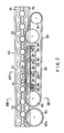
- FIG. 1 is a top view of a bottle inspection device 51 and a plurality of bottles 3 are transferred to the bottle inspection device 51 by a bottle container transportation conveyor 52.
- An inlet star wheel 53 is disposed on the upstream side of the bottle inspection device 51 and an inlet guide 54 is disposed along the star wheel 53 so as to guide the bottles 3 toward an adjacent main star wheel 55.
- An auxiliary star wheel 56 and a main guide 57 are disposed adjacent to and in opposed relationship with the main star wheel 55.
- An output star wheel 58 is disposed in opposed and spaced apart relationship with the main star wheel 55 and an outlet guide 59 is disposed along the outlet star wheel 58.
- a container rotating-transporting device 60 is disposed between the main star wheel 55 and the outlet star wheel 58.
- the device 60 comprises a plurality of bottle stands 73 upon which are placed the bottles, respectively.
- a transport device 61 holds the container stands 73 and transporting them straightly.
- a rotation-imparting means 80 comprises a travelling belt 83 which is extended by a predetermined distance in the direction in which are transported the bottle stands 73.
- Each stand 73 is supported by a pulley 70 as rotating body means (Figs. 2 and 3).
- the transport device 61 of the container rotating-transporting device 60 has a driving sprocket wheel 62 and a driven sprocket wheel 63 which are spaced apart from each other by a predetermined distance.
- An endless chain 64 is provided between the driving and driven sprocket wheels 62 and 63 and is driven by a driving motor (not shown) coupled to the rotating shaft of the driving sprocket wheel 62.
- Plate-like plastic guide rails 75 and 76 are extended on the opposite sides of the upper run of the roller chain 64 while two rod-shaped guide rails 77 and 78 are extended on the opposite sides of the lower run of the roller chain 64 (see Fig. 3).
- a plurality of L-shaped members 66a, 66b and 66c are securely attached to each of links 65 of the roller chain 64.
- a supporting plate 67 is securely mounted on the members 66a and 66b.
- a plurality of supporting shafts 68 are securely attached to the center of each of the supporting plates 67.
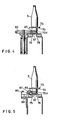
- a stand pulley 70 as rotating body means having a V-shaped groove 70V is rotatably carried through bearings 71 by each supporting shaft 68.
- a bearings 71 is securely fixed to the supporting shaft 68 having a hexagonal hole by means of a bolt 72.
- Each bottle stand 73 is detachably attached to the upper surface of the bottle stand pulley 70 in such a way that a downwardly extended bottom portion 73a of the bottle stand 73 is fitted into the opening 70a of the stand pulley 70 and an 0-ring 74 is interposed between them. Therefore, the bottle stand pulley 70 and the bottle stand 73 are brought into frictional engagement with each other so that they rotate in unison.
- a rubber plate or the like 73b is bonded to the upper surface of the stand 73 to prevent the slippage of the bottle 3, so that it becomes possible to transport it in a stable manner even at a high rotational speed.
- each container stand 73 is guided horizontally while the lower surface of the supporting plate 67 is made into sliding contact with the upper surfaces of the stationary plate-like guide rails 75 and 76, the upper surface of the stationary member 66c is brought into slidable contact with the lower surface of the plate-like guide rail 76 and the side surface of the plate-like guide rail 75 is made into slidable contact with a side plate 66d disposed on the side surface of the stationary member 66a.
- each container stand 73 is guided while the rod-shaped guide rails 77 and 78 are made into slidable contact with each supporting plate 67.
- a rotation-imparting means 80 as a rotation-imparting means is disposed along the transport device 61 and comprises a driving pulley 81 directly coupled to a variable speed motor, a driven pulley 82 and an endless belt 83 hexagonal in cross section are provided between the driving and driven pulleys 81 and 82.
- the tension of the travelling belt 83 is controlled by a tension pulley 84.
- the travelling belt 83 is adapted to engage with the V-shaped groove 70V of each stand pulley 70 of the inner run 85 of the belt 83 thereby to rotate each stand pulley 70.
- a roller supporting plate 86 is disposed along the inner run 85.
- each swinging arm 88 each having a pressure roller 87 at its outer end are pivotally connected to the roller supporting plate 86 and are spaced apart from each other by a predetermined distance.
- the inner end of each swinging arm 88 is connected to a compression coil spring 89 so that each roller 87 is pushed outside.
- a previous rotation-imparting pulley 90 is disposed on the upstream side of the transport device 61 and adjacent to the driven pulley 82.
- the pulley 90 has a rubber ring 90a around the periphery thereof. The ring 90a engages with the V-shaped groove 70V of each stand pulleys 70 so that each stand pulley 70 and stand 73 are rotated previously at an upstream position of the rotation-imparting means 80.
- a camera 92 and a light source 93 are disposed on the opposite sides, respectively, of the transport device 61 and the rotation-imparting means 80 so that each bottle 3 which passes in front of the camera 92 is inspected.
- a turntable 95 for discharging or rejecting the defective bottles is disposed adjacent to the outlet star wheel 58 and defective bottles are discharged into the turntable 95 by a rejection device 96 having an air nozzle 96a disposed adjacent to the outer periphery of the turntable 95.
- a non-defective bottle 3a is returned along the outer periphery of the turntable 95 onto the bottle transportation conveyor 51 through a guide path and transported to the next station or the like.
- the driving direction of the transport device 61 and the inner run 85 of the travelling belt 83 are the same direction.
- the transport velocity V 1 of the transport device 61 is higher than the travelling velocity V 2 of the belt 83. Under these conditions, the bottles 3 are transported while being rotated simultaneously in accordance with the present invention.
- Each bottle 3 is transported to the inlet star wheel 53 by the conveyor 51 which is driven in the direction indicated by an arrow A. Thereafter, the inlet star wheel 53 which is rotated in the direction indicated by an arrow B and the inlet guide 54 transport the bottle 3 toward the main star wheel 55. The bottle 3 is held by the main star wheel 55 which rotates in the direction indicated by an arrow C. In this case, the bottom of the bottle 3 is inspected. Next, each bottle 3 is placed on a respective bottle stand 73 of the transport device 61 by the main and auxiliary star wheels 55 and 56. As the roller chain 64 is driven, the stand 73 is transported in the direction indicated by an arrow D in Fig. 1.
- each stand pulley 70 connected to each container stand 73 is brought into contact with the previous rotation imparting pulley 90 so that the container stand 73 is rotated at a relatively low speed.
- the travelling belt 83 of the rotation-imparting means 80 is brought into engagement with the V-shaped groove 70V of each stand pulley 70.
- a rotational force is imparted to the stand pulley 70. Therefore, stand 73 is rotated at a predetermined velocity.
- the transport device 61 and the rotation-imparting means 80 are so designed and constructed that more than one rotation is given to each bottle 3. While each bottle 3 is rotated in the manner described above, the bottle 3 is completely inspected by the camera 92 and the light source 93 disposed on the opposite sides, respectively, of the transport device 61 and the rotation-imparting means 80. The inspected bottle 3 is transported by the transport device 61 toward the outlet star wheel 58 which rotates in the direction indicated by an arrow E and which in turn transfers the inspected bottles 3 to the turntable 95 which is rotating in the direction indicated by an arrow F.
- the motor for driving the driving pulley 81 of the rotation-imparting means 80 is variable in speed. Therefore, the travelling velocity V 2 of the travelling belt 83 can be selected so that the difference in velocity (V l -V 2 ) between the transporting velocity V, of the transport device 61 and the travelling velocity V 2 of the belt 83 may be arbitrarily varied. As a result, the rotational speed of each container stand 73 can be arbitrarily selected from a low speed to a high speed.
- the rotational speed or force corresponding to V I +V 2 is imparted to each stand 73.
- the container rotating-transporting device in accordance with the present invention is not needed to be provided with the suction cups and a negative pressure source. Therefore the container rotating-transporting device can be made simple in construction. As a result, the numebr of component parts can be minimized and consequently the fabrication cost can be reduced.
- each bottle is merely placed upon a bottle stand and no means for securely holding each bottle on the bottle stand is needed.
- the shape and size of the bottles can be arbitrarily selected.
- the container rotating-transporting device in accordance with the present invention makes it possible to inspect various types of containers such as elliptical bottles, square bottles, Japanese type sake bottles, cans and the like.
- the travelling belt is driven in the same direction as the container stands so that the containers are transported straightly and simultaneously rotated at a low rotational speed without any variation in rotational speed.
- the rotational speed of the containers can be varied. Therefore, the whole surface inspection of each container can be accomplished completely.
Landscapes
- Engineering & Computer Science (AREA)
- Mechanical Engineering (AREA)
- Investigating Materials By The Use Of Optical Means Adapted For Particular Applications (AREA)
- Specific Conveyance Elements (AREA)
- Sorting Of Articles (AREA)
Claims (12)
Applications Claiming Priority (4)
| Application Number | Priority Date | Filing Date | Title |
|---|---|---|---|
| JP117827/85 | 1985-05-31 | ||
| JP60117827A JPH0651532B2 (ja) | 1985-05-31 | 1985-05-31 | 容器回転搬送装置 |
| JP61087293A JPS62259919A (ja) | 1986-04-16 | 1986-04-16 | 容器回転搬送装置 |
| JP87293/86 | 1986-04-16 |
Publications (3)
| Publication Number | Publication Date |
|---|---|
| EP0203605A2 EP0203605A2 (de) | 1986-12-03 |
| EP0203605A3 EP0203605A3 (en) | 1988-01-07 |
| EP0203605B1 true EP0203605B1 (de) | 1990-09-05 |
Family
ID=26428580
Family Applications (1)
| Application Number | Title | Priority Date | Filing Date |
|---|---|---|---|
| EP86107308A Expired EP0203605B1 (de) | 1985-05-31 | 1986-05-29 | Vorrichtung zum Drehen von Behältern beim Transport |
Country Status (5)
| Country | Link |
|---|---|
| US (1) | US4832173A (de) |
| EP (1) | EP0203605B1 (de) |
| AU (1) | AU580417B2 (de) |
| CA (1) | CA1261778A (de) |
| DE (1) | DE3673872D1 (de) |
Families Citing this family (28)
| Publication number | Priority date | Publication date | Assignee | Title |
|---|---|---|---|---|
| DE3712812A1 (de) * | 1987-04-15 | 1988-10-27 | Will E C H Gmbh & Co | Vorrichtung zum drehen von bewegten gegenstaenden |
| US4975568A (en) * | 1988-02-10 | 1990-12-04 | Takeda Chemical Industries, Ltd. | Container inspecting apparatus with a light shielding member shaped to container profile |
| GB8804775D0 (en) * | 1988-03-01 | 1988-03-30 | Redland Bricks Ltd | Inverter |
| EP0332376A3 (de) * | 1988-03-07 | 1990-10-10 | Sentinel Vision Inc. | Apparat zur Inspektion von Umbördelungen bei Blechdosen und ähnlichem |
| DE3915246A1 (de) * | 1989-05-10 | 1990-11-15 | Focke & Co | Verfahren und foerdervorrichtung zur foerderung von gegenstaenden |
| FR2656238B1 (fr) * | 1989-12-26 | 1994-04-08 | Chaudronnerie Tolerie Argonne | Machine a depolir pour articles en verre. |
| DE29518628U1 (de) * | 1995-11-24 | 1997-04-10 | Heuft Systemtechnik Gmbh, 56659 Burgbrohl | Vorrichtung zum Drehen von rotationssymmetrischen Behältern wie Flaschen während des Transports unter Staudruck |
| US5979634A (en) * | 1997-10-17 | 1999-11-09 | Paper Converting Machine Company | Infeed section for packaging apparatus |
| FI108291B (fi) * | 1999-08-13 | 2001-12-31 | Bevesys Oy | Irtoastioiden, kuten pullojen, tölkkien tms., palautusautomaatin syöttölaite |
| JP3785342B2 (ja) * | 2001-09-28 | 2006-06-14 | 日立エンジニアリング株式会社 | 被検体検査装置及び透明容器の充填液体中の異物検査装置 |
| US6520314B1 (en) * | 2002-01-30 | 2003-02-18 | Samuel O. Seiling | Apparatus for arranging packaged bakery goods for shipment |
| US6808060B1 (en) * | 2003-06-30 | 2004-10-26 | Emhart Glass S.A. | Container inspection machine |
| US20060236792A1 (en) * | 2005-04-22 | 2006-10-26 | Mectron Engineering Company | Workpiece inspection system |
| DE102006062298B3 (de) * | 2006-12-27 | 2008-06-19 | Krones Ag | Vorrichtung und Verfahren zum Inspizieren von Behältnissen |
| US7565783B1 (en) * | 2007-03-19 | 2009-07-28 | Hurst Richard F | Apparatus for loading trays |
| IT1390606B1 (it) * | 2008-07-14 | 2011-09-09 | Pharmamech S R L | Procedimento per il controllo automatico a visione artificiale del fondo, del bordo bocca e della parete interna/esterna di contenitori aperti in vetro e macchina ispezionatrice realizzante detto procedimento. |
| CN101875036A (zh) * | 2009-04-30 | 2010-11-03 | 深圳富泰宏精密工业有限公司 | 转动装置 |
| US20110186405A1 (en) * | 2010-02-03 | 2011-08-04 | Maf Industries, Inc. | Methods, apparatuses, and systems for conveying and sorting produce |
| JP4590021B1 (ja) * | 2010-05-14 | 2010-12-01 | 昭和電工株式会社 | 搬送システム、搬送装置、物品、および検査システム |
| DE102011011316A1 (de) * | 2011-02-15 | 2012-08-16 | Krones Aktiengesellschaft | Vorrichtung und Verfahren zum Behandeln von Behältnissen mit Behältnisdrehung |
| DE102011083377A1 (de) * | 2011-09-26 | 2013-03-28 | Krones Aktiengesellschaft | Vorrichtung und Verfahren zum Ausrichten von Behältern |
| SG10201909092SA (en) | 2015-03-31 | 2019-11-28 | Fisher & Paykel Healthcare Ltd | A user interface and system for supplying gases to an airway |
| GB2607540B (en) | 2016-08-11 | 2023-03-29 | Fisher & Paykel Healthcare Ltd | A collapsible conduit, patient interface and headgear connector |
| JP7195565B2 (ja) * | 2017-12-28 | 2022-12-26 | 伊東電機株式会社 | コード読み取り装置及びコード読み取り方法 |
| JP7123872B2 (ja) * | 2019-07-31 | 2022-08-23 | 株式会社 日立産業制御ソリューションズ | 容器搬送装置 |
| EP3943425A1 (de) * | 2020-07-24 | 2022-01-26 | WestRock Packaging Systems, LLC | An verschiedene behälterumfänge anpassbares fördersystem zum gruppieren von behältern |
| CN111846915B (zh) * | 2020-07-27 | 2022-02-08 | 湖南海日食品有限公司 | 一种用茭头食品包装的工序连接装置 |
| US12540031B2 (en) * | 2023-11-29 | 2026-02-03 | Optum, Inc. | Continuous motion systems and methods for automatic object loading and transportation |
Family Cites Families (15)
| Publication number | Priority date | Publication date | Assignee | Title |
|---|---|---|---|---|
| US2487354A (en) * | 1945-02-14 | 1949-11-08 | Anchor Hocking Glass Corp | Conveyer for changing course of articles from single to plural rows |
| US2830462A (en) * | 1954-07-21 | 1958-04-15 | Selas Corp Of America | Apparatus for rotating work pieces moving through a furnace |
| US2928222A (en) * | 1955-08-04 | 1960-03-15 | Campbell Soup Co | Packaging machine |
| US3216550A (en) * | 1964-03-27 | 1965-11-09 | Corning Glass Works | Wareholder shaker |
| US3612254A (en) * | 1970-04-24 | 1971-10-12 | Owens Illinois Inc | Container-handling chuck |
| DE2110487A1 (de) * | 1971-03-02 | 1972-09-07 | Karl Fischer App U Rohrleitung | Verfahren und Vorrichtung zur Behandlung von Strick- oder Wirkwaren,insbesondere von Struempfen aus synthetischem Material |
| CH570912A5 (de) * | 1974-03-11 | 1975-12-31 | Emhart Zuerich Sa | |
| JPS5614245Y2 (de) * | 1975-10-14 | 1981-04-03 | ||
| DE2903470C2 (de) * | 1979-01-30 | 1989-04-06 | Otto Sick Kg, 7830 Emmendingen | Einrichtung zur Winkelausrichtung von Gefäßen |
| US4338155A (en) * | 1980-05-21 | 1982-07-06 | H. J. Heinz Company | Method and apparatus for indexing containers to be labeled |
| GB2096556B (en) * | 1981-04-14 | 1984-12-05 | Jensen Inc | Conveyor with roller support workpiece holder |
| JPS5842514A (ja) * | 1981-09-03 | 1983-03-12 | Toyo Seikan Kaisha Ltd | 空缶サイドシ−ム部の位置決め装置 |
| JPS5853099U (ja) * | 1981-10-06 | 1983-04-11 | 麒麟麦酒株式会社 | 物品の回転保持装置 |
| FR2529177A1 (fr) * | 1982-06-24 | 1983-12-30 | G 2 M Lepetit Sa | Posage associe a un convoyeur |
| DE3239541A1 (de) * | 1982-10-26 | 1984-04-26 | Krones Ag Hermann Kronseder Maschinenfabrik, 8402 Neutraubling | Verfahren und vorrichtung zum ausrichten von gefaessen |
-
1986
- 1986-05-27 US US06/867,787 patent/US4832173A/en not_active Expired - Lifetime
- 1986-05-28 AU AU58028/86A patent/AU580417B2/en not_active Ceased
- 1986-05-29 DE DE8686107308T patent/DE3673872D1/de not_active Expired - Lifetime
- 1986-05-29 EP EP86107308A patent/EP0203605B1/de not_active Expired
- 1986-05-30 CA CA000510394A patent/CA1261778A/en not_active Expired
Also Published As
| Publication number | Publication date |
|---|---|
| US4832173A (en) | 1989-05-23 |
| AU580417B2 (en) | 1989-01-12 |
| CA1261778A (en) | 1989-09-26 |
| EP0203605A2 (de) | 1986-12-03 |
| EP0203605A3 (en) | 1988-01-07 |
| AU5802886A (en) | 1987-12-03 |
| DE3673872D1 (de) | 1990-10-11 |
Similar Documents
| Publication | Publication Date | Title |
|---|---|---|
| EP0203605B1 (de) | Vorrichtung zum Drehen von Behältern beim Transport | |
| US4511025A (en) | Article holding apparatus of rotary type | |
| JP4995303B2 (ja) | 充填し封緘した容器の検査装置 | |
| US6012344A (en) | Inspection machine for containers | |
| US3975260A (en) | Bottle handling apparatus | |
| US7261197B2 (en) | Method and apparatus for inspecting articles of glassware | |
| JP3212378B2 (ja) | 容器検査装置 | |
| KR950003596B1 (ko) | 회전할출장치 | |
| CN1400449A (zh) | 用于检验非圆容器的装置和方法 | |
| US3556279A (en) | Rotary inspecting means for nonround articles | |
| US5022532A (en) | Unit for grading produce, such as fruits | |
| US3750877A (en) | Apparatus for and method of inspecting container means | |
| US20050237529A1 (en) | Wafer rotation device and edge flaw inspection apparataus having the device | |
| KR20230082282A (ko) | 과일 선별 장치 및 이를 위한 과일 적재 트레이 | |
| JPS62259919A (ja) | 容器回転搬送装置 | |
| JPS61277514A (ja) | 容器回転搬送装置 | |
| JP2009126138A (ja) | プリフォーム検査装置 | |
| JPH1135126A (ja) | 農産物保持機能を有する受皿及びこれを用いた選別装置 | |
| JPS6229329B2 (de) | ||
| US4720192A (en) | Glass bottle inspection unit | |
| JPS6216920A (ja) | 容器回転搬送装置 | |
| JP2001010723A (ja) | 容器検査装置 | |
| KR100410878B1 (ko) | 다각형 펫트병 위치제어 가이드장치 | |
| CN222058135U (zh) | 一种输送检测装置及其灯检检漏一体机 | |
| JP5066749B2 (ja) | 容器検査装置 |
Legal Events
| Date | Code | Title | Description |
|---|---|---|---|
| PUAI | Public reference made under article 153(3) epc to a published international application that has entered the european phase |
Free format text: ORIGINAL CODE: 0009012 |
|
| AK | Designated contracting states |
Kind code of ref document: A2 Designated state(s): DE FR GB |
|
| PUAL | Search report despatched |
Free format text: ORIGINAL CODE: 0009013 |
|
| AK | Designated contracting states |
Kind code of ref document: A3 Designated state(s): DE FR GB |
|
| 17P | Request for examination filed |
Effective date: 19880629 |
|
| 17Q | First examination report despatched |
Effective date: 19881017 |
|
| GRAA | (expected) grant |
Free format text: ORIGINAL CODE: 0009210 |
|
| AK | Designated contracting states |
Kind code of ref document: B1 Designated state(s): DE FR GB |
|
| ET | Fr: translation filed | ||
| REF | Corresponds to: |
Ref document number: 3673872 Country of ref document: DE Date of ref document: 19901011 |
|
| RAP2 | Party data changed (patent owner data changed or rights of a patent transferred) |
Owner name: KABUSHIKI KAISHA KIRIN TECHNO SYSTEM |
|
| PLBE | No opposition filed within time limit |
Free format text: ORIGINAL CODE: 0009261 |
|
| STAA | Information on the status of an ep patent application or granted ep patent |
Free format text: STATUS: NO OPPOSITION FILED WITHIN TIME LIMIT |
|
| 26N | No opposition filed | ||
| REG | Reference to a national code |
Ref country code: GB Ref legal event code: IF02 |
|
| PGFP | Annual fee paid to national office [announced via postgrant information from national office to epo] |
Ref country code: FR Payment date: 20050509 Year of fee payment: 20 |
|
| PGFP | Annual fee paid to national office [announced via postgrant information from national office to epo] |
Ref country code: GB Payment date: 20050525 Year of fee payment: 20 |
|
| PGFP | Annual fee paid to national office [announced via postgrant information from national office to epo] |
Ref country code: DE Payment date: 20050725 Year of fee payment: 20 |
|
| PG25 | Lapsed in a contracting state [announced via postgrant information from national office to epo] |
Ref country code: GB Free format text: LAPSE BECAUSE OF EXPIRATION OF PROTECTION Effective date: 20060528 |
|
| REG | Reference to a national code |
Ref country code: GB Ref legal event code: PE20 |