EP0201596B1 - Vorrichtung zum zyklischen umschichten eines stapels rechteckiger oder quadratischer blätter - Google Patents
Vorrichtung zum zyklischen umschichten eines stapels rechteckiger oder quadratischer blätter Download PDFInfo
- Publication number
- EP0201596B1 EP0201596B1 EP85906055A EP85906055A EP0201596B1 EP 0201596 B1 EP0201596 B1 EP 0201596B1 EP 85906055 A EP85906055 A EP 85906055A EP 85906055 A EP85906055 A EP 85906055A EP 0201596 B1 EP0201596 B1 EP 0201596B1
- Authority
- EP
- European Patent Office
- Prior art keywords
- pile
- sheet
- spring
- frame part
- contact member
- Prior art date
- Legal status (The legal status is an assumption and is not a legal conclusion. Google has not performed a legal analysis and makes no representation as to the accuracy of the status listed.)
- Expired - Lifetime
Links
Images


Classifications
-
- G—PHYSICS
- G03—PHOTOGRAPHY; CINEMATOGRAPHY; ANALOGOUS TECHNIQUES USING WAVES OTHER THAN OPTICAL WAVES; ELECTROGRAPHY; HOLOGRAPHY
- G03B—APPARATUS OR ARRANGEMENTS FOR TAKING PHOTOGRAPHS OR FOR PROJECTING OR VIEWING THEM; APPARATUS OR ARRANGEMENTS EMPLOYING ANALOGOUS TECHNIQUES USING WAVES OTHER THAN OPTICAL WAVES; ACCESSORIES THEREFOR
- G03B23/00—Devices for changing pictures in viewing apparatus or projectors
- G03B23/02—Devices for changing pictures in viewing apparatus or projectors in which a picture is removed from a stock and returned to the same stock or another one; Magazines therefor
Definitions
- the invention relates to a device for cyclically rearranging a stack of rectangular sheets or a so-called "picture changer" with the features that are mentioned in the preamble of claim 1 and are also present in the picture changer according to EP-A 113 057.
- Image changers are known from US Pat. Nos. 4,238,898, 4,238,899, 4,241,528, 4,241,529, 4,245,417, 4,259,802 and 4,376,348. All of them are based on the principle that a stack of images, in particular photo prints, is taken up by two frame parts which can be displaced relative to one another, one of which can have a viewing window. In each case with a complete movement cycle of the frame parts - that is to say to pull them apart completely and to push them together again completely - an image is taken at one end of the stack and added at the other end of the stack.
- the picture changers have the following components: A separator removes a single image from the stack; a feeder feeds images to the separator; a first holding device holds the individual image separated from the stack in one of the frame parts, while the remaining stack in the other frame part is held by a second holding device; a guide device guides the separated single image so that it reaches the other side of the remaining stack.
- a difficult problem with image changers is that very high forces may be required to separate the single sheet from the remaining stack, especially when the sheets are stuck together due to static electricity or moisture. These conditions are present, for example, in the case of photo prints, for whose cyclical rearrangement the device according to the invention is particularly intended.
- an adhesive element acts on the sheet to be separated on its exposed side facing away from the stack, the coefficient of friction of which is supposed to be greater with the material of the sheets than the coefficient of friction between two sheets.
- This adhesive element serves as a feed device and itself forms at least one element of the first holding device.
- the object of the invention is to provide a device according to the preamble of claim 1 with a reliable feed device.
- Such a device is therefore not based on the frictional engagement between the feed device and the sheet to be separated, but on positive engagement and is therefore considerably more reliable. In addition, the risk of twisting the sheet is largely eliminated.
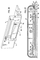
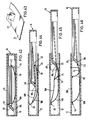
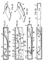
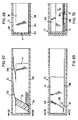
- FIG. 11 and 12 represent analogous to FIG. 9, but in two functional positions, an alternatively designed assembly.
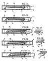
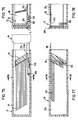
- FIGS. 37, 39 and 41 schematically illustrate in longitudinal section the functional sequence of the feed, with FIGS. 37, 39 and 41 each showing an enlarged section of the adjacent figure.
- FIGS. 42 to 46 show a further exemplary embodiment, with FIGS. 42 and 44 to 46 representing the course of the first change half cycle and FIG. 43 enlarged showing the driver.
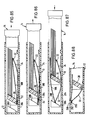
- 47 to 52 show a further embodiment in a similar form to FIGS. 42 to 46.
- 53 and 54 show an alternative feeding device in two functional positions in a schematic longitudinal sectional illustration.
- FIGS. 114 to 123 show alternative possibilities of how all sheets or images can be removed from the device.
- Figures 1 to 10 relate to a first embodiment, which is described in detail below in the interaction of all components.
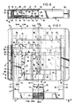
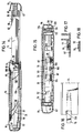
- Fig. 1 shows a partially sectioned plan view of a device according to the invention.
- the first frame part is designed as a housing 12, the second frame part is a slide 14 which can be pulled out of the housing by a stroke limited by stops 16 on the slide and counter-stops 18 on the housing and inserted again.
- the separating device is formed by a separator web 20.
- the feed device is embodied by a contact element in the form of hooks 22 which are seated on leaf spring arms 24.
- the second holding device for holding the remaining stack in the slide is also formed by the separator web, while the separated individual image in the housing by the interaction of rails arranged in the housing and provided with an adhesive coating 26 with the individual image clamping against them, through contact with them Circulation driven rollers 28, which together with the adhesive covering 26 form a first holding device, are held.
- the guiding device is embodied by pairs of leaf springs 30 and spring arms 32 formed in one piece with the spring arms 24.
- the spring arms 24 and 32 press the sheet stack (not shown in FIG. 1) against a viewing window, the inner contour of which is designated by 35.
- the top sheet in the stack should then be as flat as possible; for this purpose, it is supported on its circumference in a plane which is defined by lateral ribs 36, the underside of a handle-sliding part 38 and, on the opposite side, by ribs 40 formed on the housing.
- Fig. 1 shows the partially extended position of the slide 14. In the inserted state, the separator web is beyond these ribs 40; however, since it protrudes further to the window 35 than corresponds to the level of these ribs, it has incisions 42 for the same to pass.
- edges of the stack are supported laterally (i.e. parallel to the direction of extension) by bars 44 of the slide.
- the edges are supported by the stop surface 46 of a centrally arranged handle 48 and by lateral stop surfaces 50 on the slide.
- the edges of the photos are supported on stops 52 formed on the housing, for which the separator web also has passage recesses 54, which are, however, considerably deeper than those for the ribs 40.
- the rib 36 extends further into the interior of the slide than corresponds to the level defined by the upper edge 55 of the slide bars, so that the photos cannot slide laterally outwards over the slide bars. The corresponding effect occurs between the separator web on the one hand and ribs 40 on the other.
- the handle 48 has an upper plate 56 lying on the window side of the housing and a lower plate 57 which is wider than the upper plate; the cover wall 58 of the housing surrounding the window in the manner of a frame has a cutout 59 in the region of the upper plate, while the opposite housing wall for the lower plate 57 is recessed at 60 in a complementary manner. Accordingly, the device is in the closed state a self-contained, essentially rectangular contour without protruding parts.
- the housing and the slide are molded plastic parts.
- the slide is a one-piece element, consisting of bars, separator web, handle and an end wall 61 connecting the handle to the bars - which have an L-shaped cross section.
- the housing is composed of three parts: the lower shell 62 with the housing base 63, the frame-like upper shell 64 with window cutout, and the window 35 inserted into this.
- the housing is stiffened in the direction of the slide movement in that the struts between the top and bottom walls as double beams are carried out, as can be seen in Fig. 6.
- the housing parts can be welded together, or a snap connection can be provided.
- the window has a narrow, outwardly projecting edge 66 around its main surface, so that it protrudes somewhat from the frame surrounding it.
- a recess complementary to the contour of this edge is designated 67 on the outside of the opposite bottom wall and allows a plurality of housings to be stacked one on top of the other.
- the contact elements (hooks) 22 engage on the front edges — that is, facing away from the separator web — of the photos lying on the spring arm ends, as a result of which a certain number of photos — depending on the height of the hooks — are fed to the separating device.
- a shoe 69 belongs to each step 68, and each step / shoe system is arranged on both sides of the plane of symmetry 70 of the device.
- the shoes are longitudinally guided in the separator web, supported with a cutting edge bearing and pre-tensioned by an inserted wire spring 71.
- a roller is rotatably received in each shoe about an axis perpendicular to the direction of extension, and the roller 28 protrudes somewhat from the shoe.
- Fig. 3 one can see the position of the steps 68, which protrudes far beyond the level of the housing base by a sufficient amount of the thickness of a photo print than the surface of the adhesive coating 26.
- the lowermost section of the shoes lies a little further from the edge 72 of the Step removed, and the surface of the separator web facing the stack is beveled in a wedge-like manner such that when the separator runs onto the stack edge, the photos, on the opposite edge of which the contact elements 22 engage, "migrate” along the incline downwards in the direction of those facing them Edge 72 of the steps.
- the spring arms 32 are also overrun by the separator web. So that they do not burden the separated image from below during the passage of their ends attacking the stack during a certain phase of the pull-out stroke, they are pressed mechanically towards the housing base.
- runners 73 are formed on the slide bars 44, which sweep over extensions 74 projecting laterally from the spring arms and hold the arms on a partial stroke in accordance with their length. Additional runners 75 on the slide bars run onto the spring arms 24 on the widening 76 as soon as the individual photo is securely clamped between the adhesive covering and the rollers, and also press these arms away from the viewing window, so that one can fill in further photos unhindered and others can be removed.
- the spring arms 32 are released again after a short stroke, so that they reach under the isolated photo again and gradually lead its rear edge towards the window. Finally, under the action of the springs, this edge lies against the top of the housing. Since the free ends of the spring arms are rounded, but on the other hand this edge is to be securely clamped at the position reached, a short piece is formed in a straight line on the spring arms, designated 77 in FIG. 4. The rounded end of the spring arm finds space in a recess on the inside of the housing top wall, designated 78 in FIG. 5.
- the two contact elements 22, the two shoes 69, the adhesive pads 26 and the spring arms 32 are all each arranged symmetrically with respect to the central plane of the overall device, and the two contact elements 22 lie as precisely as possible on a line perpendicular to this plane of symmetry.
- the result of this is that the photo to be changed also goes through the changing process without being rotated if it is not guided on the slide bars due to undersize.
- the dimensional tolerances of photos are different for the same nominal size in the transverse and longitudinal directions: Since the paper from rolls is processed in rolls with a very precise width, which are then cut to different lengths, it is preferable to provide the photo dimension in the direction of the slide movement that is more tolerated.
- the single photo of the spring arms 32 is clamped in front of the stops 52 formed on the housing and is supported at four points by the spring arms 79, 80 in the direction of the separator web.
- the other transverse edge of the photo facing the separator web can sag downwards; however, the side of the separator facing it is beveled in a wedge shape, so that the edge is gradually raised when the separator web runs towards it.
- the handle-sliding part 38 is slidably received in the handle and is spring-loaded in the direction of the housing, as can be clearly seen in FIG. 3.
- the slide When the slide is inserted, its free edge 82 meets a stop 83 provided in the housing, as a result of which it is pressed back into the handle and does not protrude into the space visible through the housing window. After pulling it out, however, it secures the photos in the slider against falling out. To change the photos, it can be pushed back by hand, which is made easier by the finger edge 84.
- the photos can be pressed out from the underside of the slider, reaching between the bars, or grasped from above next to the handle.
- the separated photo always remains in the housing. It is not possible or not readily possible to remove this from the device. In order to be able to remove the stack, even if it consists of only one picture, a special device is therefore provided.
- a control bridge 85 is slidably received in the housing, held by clips 86 formed on the housing.
- the bridge carries a control button 87 which passes through the rear wall 88 of the housing and protrudes slightly beyond the changer contour. When the finger is pressed on the button, the bridge runs onto wedges 89 on the housing base and is thereby lifted towards the window.
- the width of the bridge fits into a corresponding cutout 90 in the separator and blocks the passage gap of the separating device on the entire extension stroke of the slide, so that each image in the device must be transported out with the slide.
- the means described should keep the photos at a distance from the window pane so that it does not come into contact with the image surface during the changing processes, which would result in scratch damage.
- the photos are not (always) flat, but usually have a curvature either in the longitudinal or transverse direction.
- the ribs 36 which are effective over the entire extension stroke are sufficient.
- the handle-sliding part is effective, but the opposite section of the separator web would hardly be able to absorb the considerable stresses which are similarly arched in a thicker stack Photos are taken.
- the slide front wall near the spars has inclined surfaces 92 which are substantially parallel to the opposite separator slope.
- the photos are therefore diagonally staggered between the separator and inclined surfaces, whereby a large part of the stresses in the stack are distributed over the entire surface of the separator.
- an elevation 93 is provided in the middle of the separator web, which absorbs the residual tension of those photos which are supported on the stop surfaces 50 perpendicular to their edge.
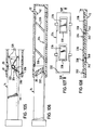
- a rack 94 is injection molded onto the housing, with which a gear 95 meshes, which is formed in one piece with its shaft 96.
- the shaft is seated in an elongated hole 97 in the slide bar 44 parallel to the rack, into which it is pressed in by means of a leaf spring 98 supported on the housing and molded onto the gearwheel.
- the slot is divided by a rib 99 into two parts, in which the shaft 96 has little lateral play.
- locking lugs 100, 101 are formed on both sides of the elongated hole on the slide and lie in the plane of the toothed ring of the gearwheel and can engage with the tips thereof.
- the gear has the position shown in FIG. 9 and that when the slider moves in the direction of arrow 102, the gear rotates in the direction of arrow 103. Due to the friction of the spring 98 on the housing wall, the gearwheel is held near the center of the elongated hole, with its shaft abutting the rib 99. This results in a distance, albeit a small one, between the tip circle of the ring gear and the tip of the nose 101. If you now try to move the slide in the opposite direction, the gear is moved to the outer end of the elongated hole and is immediately blocked by the tip 101. At the end of the slide stroke, however, the ring gear runs onto a stop pitch circle 104 and is lifted over the rib 99 while the spring 98 is deformed, so that now only the rotation in the opposite direction is released.
- the first holding device is embodied by the rollers 28 in cooperation with the adhesive pads 26 on the largest part of the slide extension stroke, but also on the last part of the stroke, shortly before reaching the end position, the spring arms 32, by clinging on the single photo, act as a "continuation" of the holding device.
- each sheet that has been shifted is never released during the entire shifting cycle, but is grasped at at least two points and thus secured against rotation. It is therefore always under control, here with axially symmetrical means.
- the stack-parallel legs of the slide spars, on which the isolated sheet is supported during the shifting may be at most such a distance from each other that a short photo, which just lies with one edge on a spar leg perpendicular to it, from the opposite spar on the other edge is held.
- the device has the viewing window in the upper shell of the housing.
- the dimension of the window in the direction transverse to the direction of movement is at most so large that the shortest possible photo, even if it is off-center, is not presented with its edge in the field of vision.
- the hooks 22 formed on them form the contact elements of the feed device, the hooks ultimately taking only one sheet into the separating device.
- both arms together - to be more precise the four arms of both springs - form a pressure system with which the stack is pressed cleanly or pretensioned against the window when the device is at rest.
- the arm 32 after having been overrun by the separator, serves to convey the single sheet to the housing top wall and, fourthly, to clamp it there.
- the arms 32 are arranged close enough next to the adhesive coverings 26 that they can peel off a single sheet that may adhere to the adhesive cover due to static charge due to their pretensioning force. It should be noted that the arm 32 is shaped and arranged in such a way that it can be overrun by the separator web without causing interference with the smooth handling.
- FIGS. 9 and 10 show a variant of the locking device according to FIGS. 9 and 10.
- frame part 14 a pinch roller 108 is rotatable about a pin 106, which, however, sits eccentrically. Compared to its largest projection, it carries a pin 110, over which a leaf spring 112 fastened to the frame part 14 engages.
- the pinch roller can deflect, but in the opposite direction it jams the two frame parts.
- the pinch roller encounters a recess 114 in the other frame part and can therefore, when the direction of thrust is reversed, pivot freely about 90 ° until the pin 110 again rests on the spring 112.
- the two locking devices described above act in the manner of a freewheel, that is to say they only switch relative to one another in the end positions of both frame parts. However, it can happen that a user wants to undo an incorrect operation, for example because a stack of photo prints has shifted when inserted. Then it is desirable, at least from certain positions, unlocked in both Directions to be able to move the frame parts relative to each other. Therefore, a different type of locking device is provided in the preferred embodiment described below.
- the embodiment is shown in its entirety.
- the slide 14 is slidably received; Housing 12 forms the first frame part, slide 14 the second.
- the pull-out stroke is limited by a bearing eye 116 which is formed on one of the slide bars 44 and which runs onto a stop 18 on the housing side.
- the housing is screwed together from an upper shell 64 and a lower shell 62, the outer edges of which interlock positively, in the region between the slide bars 44 and the outer edges of the housing parallel to them.
- the lower shell has molded-on guide sleeves 118 for screw shafts 120 and recesses 122 on the outside for screw heads 124, while the upper shell carries coaxially molded core-hole sleeves 126, into which the screws cut their own thread.
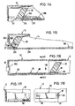
- the window 35 is clipped into the upper shell 64 and the parts of the upper shell lying under its outer edge regions are not visible because these regions of the window are matted.
- the contour of the central, transparent window section is marked with 34.
- the spring arms 24, 32 and 80 are combined into a stamped and bent part and positioned by means of cams 128 and crimped cold.
- the spring arms 79 are separate components which, as shown in FIGS. 16 to 18, are positioned on the lower shell by means of molded cams and are crimped cold. So that this spring arm can lift the isolated image as early as possible, the associated slide bar 44 has cutouts 130. The secure holding of the isolated image is ensured during this phase of the change cycle by the spring arms 80, which press the end edge of the image facing away from the slide like a clamp.
- the adhesive coating 26 can hold the isolated image so much that the force of the spring arms 79 is not sufficient to lift the image edge facing the slide.
- 19 and 20 show a first possibility of additionally pressing this edge off the adhesive covering: the two adhesive covering strips are each arranged on a separately manufactured web 134 in the form of a rail. On both sides of the strip 26, the web has molded spring bridges 132 which, after overflowing through the separator web 20, spring up and lift the image edge.
- separate metallic spring leaves 136 can be provided.
- FIGS. 32 and 33 The design of the webs 134 can be seen in FIGS. 32 and 33. It can be seen that they are mirror-symmetrical, that is to say they have steps 68 with edges 72 at both ends. The reason for this is that no sorting is then required when the webs are automatically coated with the adhesive coating. However, holes 138 must then additionally be provided, through which drive-on wedges 140 for the separator web protrude on the handle-side end of the housing on its lower shell. The webs are fastened in the lower shell by pressing the lugs 142 into corresponding grooves in the lower housing shell, and the exact positioning is carried out by means of one of the two pins 144, namely by means of the pin facing away from the slide handle, while an elongated hole on the housing side is assigned to the other pin.
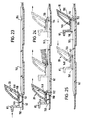
- the webs 134 also form the guide for the button 87 arranged in the plane of symmetry, the design, arrangement and function of which is shown schematically in FIGS. 23 to 25.
- Fig. 23 shows the operating position, that is, in this position of the key 87, the normal change process takes place.
- the key 87 carries an extension 146 directed towards the separator web 20 with a notch 148, to which a double wedge 150 on the underside of the separator web 20 is complementary. If you now press the button 87 while the slide is held in place, its extension 146 springs out downward until the double wedge 150 engages in the notch 148 (FIG. 24, left).
- the locking lug 152 projecting downward from the extension 146 now blocks the separating device for the edge of the bottom image in the stack, so that when the slide is pulled, the contact elements 22 also slide off the edge of this image when the separator web together with the key 87 on it facing stack edge acts and takes the stack (Fig. 24, center).
- a rib 153 prevents disengagement of the extension 146, which runs along the rib 153.
- the locking lug 152 meets an incision 154 in the rib 159, while the key guide tab 158 meets a stop 156.
- the extension can accordingly rebound downwards when the slide is pulled further, and thus detach from the separator (FIG. 24, right).
- the key can be moved loosely, so that the double wedge simply pushes it in front of itself until it has reached its end position again (FIG. 25).
- a control pawl 162 is pivotally arranged about a pin 160, which is guided along channels with a control cam 164, which are defined by guide rails 166 formed on the lower shell 62, so that the control cam 164 corresponds to the one in FIG Arrows must follow the marked paths when inserting or pulling out.
- the direction of movement can be reversed freely during most of the change cycle, but not when the control cam 164 is in the channel section 168 during insertion or in channel section 170 during extraction.
- FIG. 30 shows the end of the spring arm 24 with the contact element 22.
- extensions 180 which have the task of engaging the image from below and thus preventing the situation shown in dashed lines in FIG. 31 from occurring that a strongly curved picture is so deep in the hook 22 that it can no longer slide off the edge. This possibility must be given, however, so that the entire stack can be removed using the button 87.
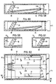
- FIG. 34 to 41 first illustrate the principle.
- the first frame part can be seen in the form of the essentially rectangular housing 12, in which the slide 14 is slidably received as the second frame part.
- the separating device is only indicated symbolically as separator web 20.
- the stack of sheets of the same format is designated by 182.
- the slide 14 comprises a handle 48 against which the front edge of the stack rests in the direction of movement, as well as the two longitudinal bars 44 next to the separator web. Between the longitudinal bars project from the bottom of the housing 12 the elements of the feed device upwards.
- the two leaf springs 24 are fixed at one end to the housing; the other end has the inclined surface of the contact element 22 resting against the stack edge (see also FIGS. 37, 41). Accordingly, the inclined surface is structurally combined with the biasing spring in the springs 24.
- a pressure is now exerted on the sheets, acting inwards from both edges, on the one hand from the separator web and on the other hand from the inclined surface of the feed device.
- the inclined surface can, however, deflect downwards due to the elasticity of the springs 24, the inclined surface sliding off one after the other at the edges of the leaves lying above the bottom sheet.
- On the bottom sheet on the other hand, there is no or only a significantly lower braking force from the separator web, so that when the inclination of the contact element 22 and the bias of the springs 24 are properly coordinated, the force applied by the component of the spring preload acting in the sheet longitudinal direction is sufficient, the bottom sheet below push through the separator web. This also overcomes the adhesive force between neighboring sheets, which plays a significant role in the design of the system.
- the feed device not only takes on this task, but also also connects the sheet separated from the remaining stack to the first frame part, that is to say represents a component of the first holding device.
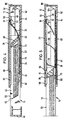
- the frame parts 12 and 14 largely correspond to the construction according to FIGS. 34 to 41.
- the difference is that incisions 184 are provided on the side of the separator web facing the housing base, which allow passage of a contact element 22 formed on the free end of the leaf springs 24.
- This has the inclined surface on its side facing the stack, while the spring sections on both sides of it for provide symmetrical support.
- the springs 24 have a rearward-facing second free end 186 with a rounded end, and the two side auxiliary springs 79 are provided on the slide bottom, but under the spars of the slide.
- the bottom sheet is presented to the separator web 20 in exactly the same way as in the embodiment according to FIGS. 34 to 41.
- the spring ends 186 are pressed down by the separator web. After they have been run over by the separator web, they can relax again and lift the sheet pushed under the separator web with its rear edge.
- This sheet is labeled 188.
- the extension stroke of the slide is dimensioned such that the spring ends next to the contact elements 22 are still suppressed by the separator web, while the spars release the auxiliary springs 79, so that they can also lift the front edge of the sheet, since these extend from the contact element 22 to has been taken in front of the separator web (cf. FIG. 46); this edge can be lifted between the slide bars and slide over the separator web when the slide is pushed back, the other edge of the sheet being supported on the stop web 52.
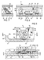
- the contact element from FIG. 48 corresponds in terms of the mode of operation to the embodiment according to FIG. 43, but it is possible to manufacture it from spring-hard steel because the sharp bending was avoided.
- the contact element inclined surface is at the same time part of the holding device for the isolated sheet. -
- the free end of the leaf spring 24 is not pressed down by the separator web at the end of the pull-out stroke, but by runners 75 molded onto the slide bars 44 and projecting inwards from the side, which run onto the areas 76 of the leaf springs.
- a recess 204 is provided in the bottom of the housing, in which a key 87 is slidable by a small distance.
- This key carries a fork-shaped stamped part 206, only half of which is shown in FIG. 49. In the rest position, as drawn, this element has no function. 47, 49 and 50, the free leaf spring end is bridged with the molded contact element 22, so that there is no more supply to the separator 20 when the slide is pulled, so that now the separator web transports all of the leaves to the outside.
- the leaf springs 24 not only perform the functions described, but also also act as a pressure arrangement with which - if it is, for example, photo prints - the top photo in the stack to one provided in the housing Viewing window is pressed.
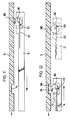
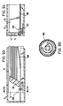
- FIG. 53 and 54 schematically illustrate that the configuration according to the invention can also operate according to the principle of kinematic reversal in such a way that the contact element 22 is rigidly provided, for example molded, on the first frame part - here in the form of a housing - during the spring preload is effected by a leaf spring 24 attached to the opposite wall 210.
- Fig. 53 shows the idle state
- Fig. 54 shows the beginning of the extension stroke of the other frame part in the form of a slide, the single sheet 188 having already been cut off.
- the contact element moves over a linkage, executes a preliminary run and thereby already feeds the next sheet to be separated to the separating device, while the previous one still comes back on the other side of the stack.
- the contact element 22 is formed by a compressible covering 212 on a carrier plate 214, which is articulated by means of a link 216 on the floor 218 of one of the frame parts.
- a femoral neck spring 24 presses the covering against the rear edge of the sheet 188 to be separated.
- the contact element 22 is designed as a plate 220 which engages behind the rear edge of the sheet 188 to be separated with a raised ledge 222.
- the biasing arrangement comprises a coil tension spring 24 which is suspended somewhere in a stationary manner and engages a parallelogram linkage arrangement 224 to which the plate is articulated. In this way, the contact element is held parallel to its main plane regardless of the stack thickness.
- the contact element 22 is an extension 226, angled by a leaf spring 24, which extends transversely to the direction of movement of the leaf 188 to be separated, which is symbolized by the arrow 228; here too the contact element is essentially always in the same operative position with respect to the sheet edge, regardless of the number of sheets in the stack.
- FIG. 58 shows the situation after a change cycle in longitudinal section.
- a stop provided on the slide 14 has aligned the edges of the sheets facing away from the separator 20, so that their ends protruding from the stack at different distances - or end edges protruding in these - form the configuration indicated in FIG. 58.
- the case where a longer sheet lies over a shorter sheet is shown separately in Fig. 59, and Fig. 61 shows schematically what could happen if no compensation were provided: the second bottom sheet is exposed with its protruding edge over the end edge of the lowermost sheet, and when separator web 20 comes up, the situation shown in FIG. 61 will occur, in which the change process is disrupted ("double sheet change").
- the separating devices are in principle similar to one another.
- other types of separating devices can also be provided within the scope of the invention, provided that it is ensured that they have a first and a second separating element comprise, which are resiliently biased towards one another and define a passage gap which, for the entry of the sheet to be separated, has a clear width of more than the thickness of one sheet and less than the thickness of two sheets. During the alternating cycle, this clear width is either kept the same or reduced to the thickness of the separated sheet.
- the one separating element is formed by the steps 68, the other by the shoes 69, which are pretensioned by the spring 71.
- the passage gap for the entry of the sheet to be separated is fixed by a mechanical stop to the defined value of the clear width.
- the clear width can either also be maintained by a system of stops, or the gap closes resiliently over the severed sheet, so that this limits the clear width itself.
- Fig. 63 shows a photo changer in schematic longitudinal section
- Fig. 64 is an associated partial cross section.
- the first frame part is designed as a housing 12, to which a first, stationary separating element in the form of a rib 238 is molded, which sits on the housing base 218.
- the second separating element is formed by a separator web 20 which is formed on a slide 14 which is displaceable relative to the housing and forms the second frame part.
- the slide 14 is pressed by a leaf spring system 240, which is mounted in the housing, along its entire extension length in the direction of the housing base and thus in the direction of the ribs 238.
- step 68 which is considerably more than one photo thicker than the rib 238, which limits the clear width of the gap.
- the springs 240 press the separator web 20 onto the surface of the separated sheet 188 facing it.
- FIG. 64 one can still see the spars 44 of the slide, between which the separator web extends and to which it extends is integrally formed.
- FIGS. 65 and 66 differs from the one described above in that not the entire slide 14 but only a part 242 of the separator web 20 is pressed in the direction of the housing base 218 by a spring arrangement 71 which is accommodated in the latter itself while the slider is supported in this direction. The function is otherwise the same.
- FIGS. 67 and 68 differs from that according to FIGS. 63, 64 in that here too the slide is pressed by the leaf spring system 240 in the direction of the housing base 218, but no step is provided on the housing ; rather, shoes 246 are formed on the separator web 20 on both sides of the sheet passage gap 244, which are supported on the housing base 218 and thus constantly keep the clear width of the gap at the desired value.
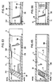
- FIG. 69 longitudinal section
- 70 partial cross section
- a holder 248 is formed which holds a stationary end of an elastic leaf spring 250 clamped in on the broad side.
- the rounded end of the leaf spring follows step 68 and, after passing its edge 72, lies on the isolated leaf 188.
- FIGS. 71 (longitudinal section) and 72 (partial cross section) likewise has a separating element which is resiliently deflectable relative to the slide 14 in the form of a separator web 20 which can be pivoted about a shaft 252 in the slide bars 44, but by a spring arrangement 240 with it Edge 254 is held in contact with the opposite part, that is, first at step 68 and after passing edge 72 on the isolated sheet 188.
- FIGS. 73 (longitudinal section) and 74 (partial cross section) comprises a housing 12 as the first frame part and a slide 14 as the second frame part.
- a foot plate 256 is inserted between the bars 44 of the slide and forms a first separating element.
- the second separating element is a separator web 20 preloaded relative to the slide in the direction of the housing base 218 by a spring arrangement 240, which is guided on rails 258 and has stop shoes 246 at its lower end on both sides of the sheet to be separated.
- 75 (longitudinal section) and 76 (partial cross section) show an embodiment in which the first frame part is formed by a slide 14 which can be pushed back and forth relative to a housing 12 as the second frame part. It is understood that here, as in all other embodiments, the maximum stroke of the slide is limited by stops, which are not drawn for clarity.
- a separator web 20 is integrally formed on the housing 12 as the first separating element, against which a second separating element in the form of an articulated (joint 260) plate 264 is provided, which is pressed by a spring 240 in contact with lateral support extensions 262 of the separator web.
- the plate 264 can thus compensate for manufacturing-related tolerances, while the gap height is always determined by the height of the extensions 262, which is practically unchangeable.
- 77 (longitudinal section) and 78 (partial cross section) show an embodiment in which the housing 12 forms the second frame part and a slide (not shown) the first frame part.
- a separator web 20 is slidably guided on the housing transversely to the main stack plane and is pretensioned by a spring arrangement 240. With its support extensions 262, it defines the gap height, which is defined on the other side by the housing top wall 266.
- first holding devices based on the same principle are provided, by means of which the separated sheet is held on the first frame part.
- differently designed first holding devices can be used, which are illustrated in FIGS. 79 to 96 and are explained below.
- Fig. 79 is a partial longitudinal section
- Fig. 80 is a horizontal section
- Fig. 81 is a cross section through the corresponding planes of the device.
- the first frame part has the shape of a housing 12, the second the shape of a slide 14.
- the separating device in the form of the separator 20 spans the slide bars 44 transversely.
- the separator presses on the control wings 268 of two levers 270 that um Axes extending parallel to the pull-out direction are pivotable, which are designated by 272.
- the levers are biased by a leaf spring 276 such that the arms 274 have a tendency to pivot in the direction of the stack of sheets inserted.
- the separator When the slider has traveled a stroke length sufficient to push the single image under the passage gap of the separator by means of the driver (not shown), the separator gradually releases the wings 268 and the arms 274 lay down from below on the now lowest sheet of the Remaining stack and behind the edge of the sheet left in the housing, so that it will surely remain in the housing while the separator transports the remaining stack out of the housing.
- the preload of the spring lifting the arms 274 can be so great that their free ends not only rest against the rest of the stack, but also lift it up a little: the single sheet cannot slide off the arms.
- the separator In the end position of the slide, the separator can just push the arms 274 down against the spring force, since it has a correspondingly beveled shape and acts as a wedge.
- the remaining stack comes back with the separator and the pusher and lies on the arms. Only when the separator slides onto the wings, are the arms folded back into the starting position.
- 82 and 84 show in longitudinal section the idle state or the partially pulled-out state of a device according to the invention, in which the first frame part is formed by a housing 12 and the second by a slide 14.
- a spring arrangement 24/32 and the separator web 20 can be seen as a separating device.
- the feed device carries out the bottom sheet 188 in the housing under the separator web, behind which a pivotable jaw 278 is arranged so as to be rotatable about a joint 289.
- a spring 282 biases the jaw 278 into the position shown in FIG. 84, as can be seen from the enlarged illustration in FIG. 83.
- the separator bar has the jaw in the inactive when the slide is inserted Position changed due to wedge effect when accruing. The jaw can be released automatically when moving out, but this is not shown in detail.
- the sheet to be separated is supplied by means of the contact element, namely the hook 22, which is seated on the spring arm 24.
- Housing, slide and separator web correspond to the previously described designs.
- the slide 14 serving as the second frame part couples after a certain extension length to a bracket 284 which is arranged in a longitudinally displaceable manner in the housing 12 forming the first frame part.
- a depression 286 is formed on the bracket below a guide surface 288.
- Fig. 88 shows a largely schematic partial longitudinal section of an embodiment in which the separator web 20 attached to the slide 14 gradually releases the leaf spring 32 attached to it as a result of pulling the slide out of the housing 12, so that its free end, provided with an adhesive coating 290, applies to the sheet edge 292 and this presses against the housing top wall 266, which then forms the other jaw in cooperation with the first jaw formed by the spring.
- FIG. 89 shows a modification of the pliers arrangement according to FIG. 88: the adhesive covering 290 is located on a pressing arrangement, consisting of a plate 294 carrying the adhesive covering, which is articulated at the end of a lever 296. The lever is hinged to the housing base 218. A spring 298 presses the adhesive coating against the isolated image.
- 90 to 92 relate to another type of the first holder.
- FIG. 90 shows a schematic longitudinal section of a device according to the invention
- FIG. 91 is a partial cross section to this figure
- FIG. 92 shows a partial horizontal section.
- the holding device has a first clamping element in the form of a roller that runs along with the separator web, a second clamping element in the form of the adhesive coating fixed to the first frame part (housing) and a spring arrangement in the form of the shoe against the adhesive pad pressing spring, the clamping elements are here formed in kinematic reversal so that the adhesive pad is provided on the circumference of a roller 300, which via a rack 302 and a pinion 304 keyed to the roller when pulling out the slide 14, which is the second Forms frame part, is driven to circulate.
- the roller has a diameter equal to the pitch circle of the pinion, so that it rolls on the single sheet at a peripheral speed which is equal to the pull-out speed of the slide.
- the single sheet is pressed against the bottom 218 of the first frame part in the form of the housing 12 and held in this.
- the device according to FIGS. 93 to 95 shows a further embodiment of the first holding device.
- the single sheet 188 arrives behind the separator web 20 in the working gap between two rollers 300, 306, of which at least one is driven in the same way as described in FIGS. 90 to 92.
- the other roller can also be driven directly by the first one, or can be carried along by friction.
- the contact pressure is generated in that one of the rollers, preferably the non-driven one, is designed to be resilient in itself and its shaft has moved somewhat closer to the other roller than would actually correspond to the diameter.
- the cross section through such a resilient roller is shown in Fig. 95, and it can be seen that recesses in themselves extend meandering around the hub, so that there is always enough spring travel available.
- the second roller 306 takes over the role of the clamping element arranged in a rail-like manner in FIGS. 1 to 10 or 13 to 33 in the first frame part, for which purpose it is rotatably mounted not on the first but on the second frame part holding the stack.
- FIGS. 1 to 57 shows a roller 300 rotatably mounted in the housing 12, which here is the second frame part, which is driven to a peripheral speed by means of a toothed rack (not shown) fitted in the slide bars 44 and a pinion (not shown) wedged to the roller , which is equal to the pull-out speed of the slide.
- the isolated image 188 is captured behind the separator web 20, pressed against the housing top wall 266 along which it slides, and released in the outer slide end position.
- the guide device can also differ from the embodiment according to FIGS. 1 to 10 and 13 to 33. This is illustrated below with reference to FIGS. 97 to 113.
- the various aspects of the guide device were only discussed in passing. However, it also has certain complications, especially for photo prints. Since the isolated sheet can be quite strongly curved under certain circumstances, it proves expedient or even inevitable to observe certain precautionary measures when designing the guide device. Thus, the isolated photo must again be passed through a passage of the separating device to the other side of the stack, even if this passage is much less critical than the separating passage. - In principle, all constructions that can be used for the feed can also be adapted for the return of the single sheet. In general, however, it is sufficient to push the photo from its rear edge, possibly still holding it in place. Some embodiments are briefly described below.
- a thin, elastic lamella 308 is arranged, which engages between the hold-down device 36 on a top wall of the first frame part.
- the free end of the lamella presses on the sheet of the remaining stack 182 facing it.
- the lamella is supported in the second frame part by a short distance in the direction of movement of the frame, so that it moves to the left at the beginning of the next change cycle (in FIG. 97). can avoid, but still blocked the passage 310, so that the last returned sheet is pressed by the hold-down on the remaining stack before the slat is retracted.
- spring 32 holds the rear sheet edge in front of the sliding stop 52
- spring 80 supports the sheet approximately in the middle
- the separator web 20 the remaining stack 182 is held at a level according to arrow 312 by the hold-down device 81 act on him.
- the arrow 314 defines the level of that edge of the separator web which is overrun by the single sheet and which is in meshing engagement with the hold-down devices.
- Fig. 99 is a schematic partial sectional side view showing a structure to prevent a sheet from being mistakenly caught in the nip during the separation phase of the change cycle on the sheet return passage. This requires the ribs 40, which engage like a comb in recesses in the separator web 20.
- blocking members 316 extending from the separator web are shown in FIG. 100, which only release the passage (either by spring action as a result of wedge run-out or positively controlled) when a sheet edge is present in the return phase (“check valve principle”).
- the following figures relate to means for ensuring the sheet return itself.
- the single sheet is preferably pushed through the passage, with its rear edge abutting a stop. If the sheet is curved by a radius of curvature which is approximately perpendicular to the direction of movement, there is a risk that the sheet will not be pushed through the passage, but will be compressed and / or slip off the stop.
- means are to be provided in the guide device that hold the single sheet as securely as possible against the "pushing" stop, and / or means that compensate or mitigate any curvature of the photo.
- a first leaf spring 32 clamps the single leaf 188 in front of the "pushing" stop 52, and further leaf springs 79, 80 press the leaf as flat as possible against the top wall of the housing 12 (first frame part), to present the leading edge of the cut sheet somewhat in front of the passageway 310.
- the reliability will be the better the longer the leaf springs attack the single leaf during the sheet return, before these springs are overrun by the separator web 20 of the separating device.
- the side of the separator web facing the single sheet 188 is preferably beveled in such a way that a leading edge of the single sheet which bulges downward in front of it can "climb up” along the slope due to the wedge effect of this slope. However, if this sheet edge is forcibly presented to the return passage by other means, the corresponding surface of the separator web can also be designed to run perpendicular to the sheet plane.
- FIG. 102 A wedge 318 has been pushed by a spring 320 under this edge of the sheet 188 and has lifted it in front of the pushing stop 52, during the first half of the change cycle. The other sheet edge is then, after passing through the separator web 20, lifted by a leaf spring 79 in front of the return passage 310. Towards the end of the second phase of the change cycle, the separator web then pushes the wedge 318 back.
- the spring 320 the wedge 318 could also be moved back and forth by a coupling to the second frame part, but with a phase shift.
- Fig. 103 schematically shows the top view of the wedge 318
- Fig. 104 shows the situation at the reversal point of the change cycle.
- a wire spring 324 can be pivoted with its eyelet around a pin 322.
- One of her arms is angled and grips transversely from the outside under the relevant edge of the single sheet, the other arm can be folded down by running onto a stop 326, taking the angled arm 328 with it and thus lifting the sheet edge.
- a locking device 330 is indicated to prevent uncontrolled movements of the mechanism; this should only be reversed in the two end positions (rest position / reversal point).
- 106 to 108 show a variant of the lever arrangement as a guide device.
- the separator web 20 runs onto a catch hook 332 of a lever carrier 334, to which two levers 336 are articulated by means of molded-on joints 338.
- the cams 340 formed on the underside of the levers run onto stops 342 of a control cam, so that the levers are raised.
- the separator web first hits the lever closer to it and pushes the entire lever support back a little way until the lever is turned; the other lever, however, remains still because the stops 342 for the two levers are at a greater distance from one another than the associated cams.
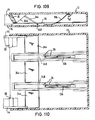
- the embodiment according to FIGS. 109 and 110 represents an embodiment in which the holding device for the single image comprises adhesive coverings 26 in the first frame part.
- the single sheet can adhere so firmly to the adhesive coverings that considerable forces are required to tear it off there. However, it must be directed to the side of the frame part facing away from the adhesive coverings. Therefore springs 136 are provided in the middle between two adhesive coverings.
- the edge of the single sheet facing the separator web 20 is lifted by a lever 344, which by means of control bevels 346 at the ends of the slide bars 44 are depressed while being lifted by spring force (not shown).
- the lever as can be seen in FIG. 110, extends over the entire width of the device, and in particular it also acts directly on the single sheet next to the adhesive coverings.
- the shaft of the lever is indicated at 348.
- 111 to 113 show a further variant.
- a lamella 350 is arranged on both sides of the adhesive coating 26, which engages resiliently in a corresponding recess next to the adhesive coating.
- the two slats are connected to one another by a bridge 352.
- FIGS. 1 to 10 on the one hand and FIGS. 13 to 33 on the other hand each show means to enable the entire stack to be removed from the device.
- 114 to 123 show variants and also means which act in principle differently for this purpose and which are explained below.
- Fig. 114 shows in partial longitudinal section an embodiment in which the separating device can optionally be locked by manual intervention. It is assumed that there is a separating device according to FIGS. 63, 64, but here only the separator web 20 is drawn by the slide.
- the step 354 is not stationary, as in FIGS. 63 and 64, but can be displaced in the direction of slide movement, the displacement being able to be done manually by means of a button 87 protruding through the housing base 218. In the position shown with solid lines, this corresponds to FIG. 63 (normal operation).
- the wedge-shaped end 356 engages under the edge of the sheet 188 in the bottom sheet 188 facing it and lifts it onto step 354, so that the passage gap under the separator web is "closed".
- the stack removal function can also be controlled manually in the embodiment according to FIG. 115 (partial longitudinal section). It is assumed that the initial construction according to FIGS. 67 and 68 is provided.
- the separator web 20 has an opening in which a blocking block 358 is slidably arranged.
- the changer In the position shown with solid lines, the changer is switched to the alternating function, the block snapping into a corresponding opening in the opening by means of cams 360. If it is moved by pressing a button 87, which resiliently rests on an integrally formed spring 362 and is connected to the housing 12, into the locking position shown in dashed lines, in which it can also be locked by means of cams 360, the passage gap is blocked, and all the sheets in the stack are transported out. If the blocking block then runs onto a stop 364 formed on the housing base 218, it is pushed back into its rest position, and the changer is switched back to the "change" function.
- a one-piece component 85 can be displaced in the longitudinal direction by pressing the button 87, the rail connected to the button running on ramps 89 and thereby lifting the entire component 85; a space 366 for the key is provided in the housing for this purpose.
- By lifting the rail it lies against the edge of the separator web 20 which delimits the passage gap from below. From this end of the rail there are still lugs 91 which, when the separator web overflows the lugs and take the entire stack with them, can spring down.
- FIGS. 119 and 120 show a further embodiment of a separating system which can be switched over for stack removal, in partial longitudinal section or in partial top view. It is assumed that in principle the type according to FIGS. 65, 66 is present. - The stage labeled 68 in FIG. 63, which is also present in FIG. 65, is very narrow and is designed in duplicate. The part 69 delimiting the passage gap, which is arranged resiliently in the separator web 20, has a recess opposite the gap between the two steps 68 front extension blocks the passage gap by lying in front of the lower edge of the separator web, and engages with a rear extension 370 behind the separator web.
- leaf springs 372 press the blocking shoe in the direction of the housing base. - If the button 87 is pressed and the blocking shoe is brought into driving connection with the separator web, whereby the separating function is blocked, and is then pulled on the slide, the blocking shoe is simply taken along. When inserted again, the little springs 372 then press the shoe back into the release position, which is provided in a trough-shaped manner behind the run-up ramp 374.
- the changing mechanism is only functional when the device contains at least two sheets.
- Fig. 121 shows this solution in a schematic longitudinal section.
- the stop 51 pushing back the single sheet is arranged at one point compared to the exemplary embodiment described at the outset, so that the single sheet 188 does not become completely flush with the rest of the stack, but instead stuck with its pushed edge on the separator web 20.
- a special step is provided for this purpose, which is designated by 376 in FIG. 122 (horizontal partial section).
- this sheet is thrown off by the two arms 378 rotatably mounted on the separator web with their outer lever arms running on stops 380 on the housing, so that their inner arms promote the image in the direction of the slide handle. On the return stroke, the levers are brought back into the starting position by hitting stops 382.
- this sheet comes into contact with the contact element, which is indicated as an oblique hook 22, when the slide is reinserted, but cannot enter the separating device ( ie do not get under the separator web). The edge slips off the hook and the slider takes the sheet out.
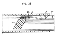
- Fig. 123 shows a variant of this principle.
- the intermediate stage for the sheet 188 is formed by a plate 384 which can be moved out of the separator web 20 by spring force, but which is pressed back when it hits stops in the fully extended slide position.
- a hold-down web 81 formed on the housing 12 ensures that the sheet 188 is pressed below the level of the plate when it comes out of the separator at the beginning of the insertion.
Landscapes
- Physics & Mathematics (AREA)
- General Physics & Mathematics (AREA)
- Sheets, Magazines, And Separation Thereof (AREA)
- Photographic Processing Devices Using Wet Methods (AREA)
- Containers And Packaging Bodies Having A Special Means To Remove Contents (AREA)
- Apparatus For Radiation Diagnosis (AREA)
- Fixed Capacitors And Capacitor Manufacturing Machines (AREA)
Priority Applications (1)
| Application Number | Priority Date | Filing Date | Title |
|---|---|---|---|
| AT85906055T ATE72905T1 (de) | 1984-11-13 | 1985-11-12 | Vorrichtung zum zyklischen umschichten eines stapels rechteckiger oder quadratischer blaetter. |
Applications Claiming Priority (2)
| Application Number | Priority Date | Filing Date | Title |
|---|---|---|---|
| DE3441482 | 1984-11-13 | ||
| DE19843441482 DE3441482A1 (de) | 1984-11-13 | 1984-11-13 | Vorrichtung zum zyklischen umschichten eines blattstapels |
Publications (2)
| Publication Number | Publication Date |
|---|---|
| EP0201596A1 EP0201596A1 (de) | 1986-11-20 |
| EP0201596B1 true EP0201596B1 (de) | 1992-02-26 |
Family
ID=6250197
Family Applications (1)
| Application Number | Title | Priority Date | Filing Date |
|---|---|---|---|
| EP85906055A Expired - Lifetime EP0201596B1 (de) | 1984-11-13 | 1985-11-12 | Vorrichtung zum zyklischen umschichten eines stapels rechteckiger oder quadratischer blätter |
Country Status (14)
| Country | Link |
|---|---|
| US (2) | US4787162A (ko) |
| EP (1) | EP0201596B1 (ko) |
| JP (1) | JPS62500818A (ko) |
| KR (1) | KR880700313A (ko) |
| AU (1) | AU581721B2 (ko) |
| BR (1) | BR8507054A (ko) |
| CA (1) | CA1269530A (ko) |
| DE (2) | DE3441482A1 (ko) |
| DK (1) | DK155970C (ko) |
| ES (1) | ES8701114A1 (ko) |
| GB (1) | GB2181114B (ko) |
| NO (1) | NO166603C (ko) |
| WO (1) | WO1986003028A1 (ko) |
| ZA (1) | ZA858702B (ko) |
Families Citing this family (8)
| Publication number | Priority date | Publication date | Assignee | Title |
|---|---|---|---|---|
| DE3441482A1 (de) * | 1984-11-13 | 1986-08-21 | Licinvest Ag, Chur | Vorrichtung zum zyklischen umschichten eines blattstapels |
| DE3441464A1 (de) * | 1984-11-13 | 1986-10-02 | Licinvest Ag, Chur | Vorrichtung zum zyklischen umschichten eines blattstapels |
| US5193795A (en) * | 1987-11-21 | 1993-03-16 | Licinvest Ag | Device for the cyclic rearrangement of a pile of sheets |
| DE3739500A1 (de) * | 1987-11-21 | 1989-06-01 | Licinvest Ag | Vorrichtung zum zyklischen umschichten eines blattstapels |
| NZ242742A (en) * | 1991-06-05 | 1993-12-23 | Licinvest Ag | Reciprocating drawer device for cyclically rearranging a stack of sheets |
| US6385473B1 (en) | 1999-04-15 | 2002-05-07 | Nexan Limited | Physiological sensor device |
| US20060072303A1 (en) * | 2004-10-06 | 2006-04-06 | Dunkle Thomas K | Marine warning sign |
| US8206223B2 (en) * | 2007-04-27 | 2012-06-26 | Mattel, Inc. | Computer fashion game with machine-readable trading cards |
Family Cites Families (19)
| Publication number | Priority date | Publication date | Assignee | Title |
|---|---|---|---|---|
| US3495345A (en) * | 1967-05-12 | 1970-02-17 | John H Weggeland | Picture viewer |
| FR2134724A5 (ko) * | 1971-04-19 | 1972-12-08 | Naguet Pierre | |
| US4057920A (en) * | 1975-11-24 | 1977-11-15 | Weggeland John H | Picture viewer with successive feed means |
| DE2745214C3 (de) * | 1977-10-07 | 1984-07-26 | Licinvest Ag, Chur | Vorrichtung zum wechselweisen Exponieren einzelner Blätter aus einem Blattstapel, insbesondere Photobetrachtungswechsler |
| DE2742346C3 (de) * | 1977-09-20 | 1980-04-17 | Licinvest Ag, Chur (Schweiz) | Bildbetrachtungsgerät |
| GR66050B (ko) * | 1977-09-20 | 1981-01-14 | Licinvest Ag | |
| DE2742345C3 (de) * | 1977-09-20 | 1981-08-06 | Licinvest Ag, Chur | Bildbetrachtungsgerät mit Wechselmechanik |
| DE2742349C3 (de) * | 1977-09-20 | 1981-06-25 | Licinvest Ag, Chur | Bildbetrachtungsgerät |
| DE2742350C3 (de) * | 1977-09-20 | 1981-06-25 | Licinvest Ag, Chur | Bildbetrachtungsgerät |
| US4173838A (en) * | 1978-04-28 | 1979-11-13 | Joseph Antos | Compact repeating slide viewer |
| DE2833464A1 (de) * | 1978-07-29 | 1980-02-07 | Licinvest Ag | Bildbetrachtungsgeraet |
| DE2912941C2 (de) * | 1978-09-06 | 1984-12-13 | Licinvest Ag, Chur | Bildbetrachtungsgerät |
| DE2914351A1 (de) * | 1979-04-09 | 1980-10-30 | Licinvest Ag | Bildbetrachtungsgeraet |
| IE49059B1 (en) * | 1978-10-11 | 1985-07-24 | Licinvest Ag | Episcope |
| DE3014394C2 (de) * | 1980-04-15 | 1982-04-22 | Reflecta Gmbh Foto Film Projektion, 8540 Schwabach | Kassettenalbum |
| DE3236643A1 (de) * | 1982-10-04 | 1984-04-05 | Licinvest AG, 7002 Chur | Behaelter zur aufbewahrung eines bilderstapels |
| DE3246101A1 (de) * | 1982-12-13 | 1984-06-14 | Licinvest Ag, Chur | Bildwechsler |
| US4550516A (en) * | 1982-12-13 | 1985-11-05 | Licinvest Ag | Picture viewer |
| DE3441482A1 (de) * | 1984-11-13 | 1986-08-21 | Licinvest Ag, Chur | Vorrichtung zum zyklischen umschichten eines blattstapels |
-
1984
- 1984-11-13 DE DE19843441482 patent/DE3441482A1/de not_active Withdrawn
-
1985
- 1985-11-12 US US06/890,023 patent/US4787162A/en not_active Expired - Fee Related
- 1985-11-12 AU AU52040/86A patent/AU581721B2/en not_active Ceased
- 1985-11-12 DE DE8585906055T patent/DE3585442D1/de not_active Expired - Fee Related
- 1985-11-12 WO PCT/EP1985/000614 patent/WO1986003028A1/de active IP Right Grant
- 1985-11-12 JP JP61500039A patent/JPS62500818A/ja active Pending
- 1985-11-12 GB GB8616717A patent/GB2181114B/en not_active Expired
- 1985-11-12 CA CA000495146A patent/CA1269530A/en not_active Expired - Fee Related
- 1985-11-12 BR BR8507054A patent/BR8507054A/pt not_active IP Right Cessation
- 1985-11-12 EP EP85906055A patent/EP0201596B1/de not_active Expired - Lifetime
- 1985-11-13 ZA ZA858702A patent/ZA858702B/xx unknown
- 1985-11-13 ES ES548822A patent/ES8701114A1/es not_active Expired
-
1986
- 1986-07-11 KR KR1019860700451A patent/KR880700313A/ko not_active Application Discontinuation
- 1986-07-11 DK DK331486A patent/DK155970C/da not_active IP Right Cessation
- 1986-07-11 NO NO86862820A patent/NO166603C/no unknown
-
1988
- 1988-09-30 US US07/252,874 patent/US4993179A/en not_active Expired - Fee Related
Also Published As
| Publication number | Publication date |
|---|---|
| KR880700313A (ko) | 1988-02-22 |
| AU5204086A (en) | 1986-06-03 |
| ES8701114A1 (es) | 1986-11-16 |
| GB2181114B (en) | 1989-04-05 |
| NO862820L (no) | 1986-09-15 |
| NO166603C (no) | 1991-08-14 |
| NO166603B (no) | 1991-05-06 |
| CA1269530A (en) | 1990-05-29 |
| NO862820D0 (no) | 1986-07-11 |
| JPS62500818A (ja) | 1987-04-02 |
| DK155970C (da) | 1989-10-23 |
| BR8507054A (pt) | 1987-03-10 |
| US4787162A (en) | 1988-11-29 |
| DK331486D0 (da) | 1986-07-11 |
| GB8616717D0 (en) | 1986-08-13 |
| DK155970B (da) | 1989-06-05 |
| DK331486A (da) | 1986-07-11 |
| ES548822A0 (es) | 1986-11-16 |
| DE3441482A1 (de) | 1986-08-21 |
| EP0201596A1 (de) | 1986-11-20 |
| GB2181114A (en) | 1987-04-15 |
| WO1986003028A1 (en) | 1986-05-22 |
| DE3585442D1 (de) | 1992-04-02 |
| ZA858702B (en) | 1986-09-24 |
| US4993179A (en) | 1991-02-19 |
| AU581721B2 (en) | 1989-03-02 |
Similar Documents
| Publication | Publication Date | Title |
|---|---|---|
| EP0201550B1 (de) | Vorrichtung zum umschichten eines blattstapels | |
| CH634665A5 (de) | Bildbetrachtungsgeraet mit einer bildwechselmechanik. | |
| CH634157A5 (de) | Bildbetrachtungsgeraet. | |
| EP0201596B1 (de) | Vorrichtung zum zyklischen umschichten eines stapels rechteckiger oder quadratischer blätter | |
| EP0203155B1 (de) | Vorrichtung zum zyklischen umschichten eines stapels rechteckiger oder quadratischer blätter | |
| EP0201552B1 (de) | Vorrichtung zum umschichten eines bilderstapels | |
| EP0204757B1 (de) | Vorrichtung zum zyklischen umschichten eines stapels rechteckiger oder quadratischer blätter | |
| DE3441454A1 (de) | Vorrichtung zum zyklischen umschichten eines blattstapels | |
| EP0201551B1 (de) | Vorrichtung zum zyklischen umschichten eines stapels rechteckiger oder quadratischer blätter | |
| EP0201594B1 (de) | Vorrichtung zum zyklischen umschichten eines stapels rechteckiger oder quadratischer blätter | |
| EP0203154B1 (de) | Vorrichtung zum zyklischen umschichten eines stapels rechteckiger oder quadratischer blätter | |
| EP0202283B1 (de) | Vorrichtung zum zyklischen umschichten eines blattstapels | |
| EP0344251B1 (de) | Vorrichtung zum zyklischen umschichten eines blattstapels | |
| EP0287620A1 (de) | Bildwechsler | |
| DE2742351C3 (de) | Bildbetrachtungsgerät | |
| DE2912941A1 (de) | Bildbetrachtungsgeraet | |
| DE4202063A1 (de) | Vorrichtung zum zyklischen umschichten eines blattstapels | |
| DE4118390A1 (de) | Vorrichtung zum zyklischen umschichten eines blattstapels |
Legal Events
| Date | Code | Title | Description |
|---|---|---|---|
| PUAI | Public reference made under article 153(3) epc to a published international application that has entered the european phase |
Free format text: ORIGINAL CODE: 0009012 |
|
| 17P | Request for examination filed |
Effective date: 19860607 |
|
| AK | Designated contracting states |
Kind code of ref document: A1 Designated state(s): AT BE CH DE FR GB IT LI NL SE |
|
| 17Q | First examination report despatched |
Effective date: 19880229 |
|
| GRAA | (expected) grant |
Free format text: ORIGINAL CODE: 0009210 |
|
| AK | Designated contracting states |
Kind code of ref document: B1 Designated state(s): AT BE CH DE FR GB IT LI NL SE |
|
| REF | Corresponds to: |
Ref document number: 72905 Country of ref document: AT Date of ref document: 19920315 Kind code of ref document: T |
|
| REF | Corresponds to: |
Ref document number: 3585442 Country of ref document: DE Date of ref document: 19920402 |
|
| ET | Fr: translation filed | ||
| ITF | It: translation for a ep patent filed |
Owner name: STUDIO TORTA SOCIETA' SEMPLICE |
|
| GBT | Gb: translation of ep patent filed (gb section 77(6)(a)/1977) | ||
| PGFP | Annual fee paid to national office [announced via postgrant information from national office to epo] |
Ref country code: CH Payment date: 19921116 Year of fee payment: 8 |
|
| PGFP | Annual fee paid to national office [announced via postgrant information from national office to epo] |
Ref country code: BE Payment date: 19921125 Year of fee payment: 8 |
|
| PGFP | Annual fee paid to national office [announced via postgrant information from national office to epo] |
Ref country code: SE Payment date: 19921126 Year of fee payment: 8 |
|
| PGFP | Annual fee paid to national office [announced via postgrant information from national office to epo] |
Ref country code: AT Payment date: 19921127 Year of fee payment: 8 |
|
| ITTA | It: last paid annual fee | ||
| PGFP | Annual fee paid to national office [announced via postgrant information from national office to epo] |
Ref country code: NL Payment date: 19921130 Year of fee payment: 8 |
|
| PLBE | No opposition filed within time limit |
Free format text: ORIGINAL CODE: 0009261 |
|
| STAA | Information on the status of an ep patent application or granted ep patent |
Free format text: STATUS: NO OPPOSITION FILED WITHIN TIME LIMIT |
|
| 26N | No opposition filed | ||
| PG25 | Lapsed in a contracting state [announced via postgrant information from national office to epo] |
Ref country code: AT Effective date: 19931112 |
|
| PG25 | Lapsed in a contracting state [announced via postgrant information from national office to epo] |
Ref country code: SE Effective date: 19931113 |
|
| PG25 | Lapsed in a contracting state [announced via postgrant information from national office to epo] |
Ref country code: LI Effective date: 19931130 Ref country code: CH Effective date: 19931130 Ref country code: BE Effective date: 19931130 |
|
| BERE | Be: lapsed |
Owner name: LICINVEST A.G. Effective date: 19931130 |
|
| PG25 | Lapsed in a contracting state [announced via postgrant information from national office to epo] |
Ref country code: NL Effective date: 19940601 |
|
| NLV4 | Nl: lapsed or anulled due to non-payment of the annual fee | ||
| REG | Reference to a national code |
Ref country code: CH Ref legal event code: PL |
|
| PGFP | Annual fee paid to national office [announced via postgrant information from national office to epo] |
Ref country code: GB Payment date: 19941111 Year of fee payment: 10 |
|
| PGFP | Annual fee paid to national office [announced via postgrant information from national office to epo] |
Ref country code: FR Payment date: 19941118 Year of fee payment: 10 |
|
| PGFP | Annual fee paid to national office [announced via postgrant information from national office to epo] |
Ref country code: DE Payment date: 19950119 Year of fee payment: 10 |
|
| EUG | Se: european patent has lapsed |
Ref document number: 85906055.0 Effective date: 19940610 |
|
| PG25 | Lapsed in a contracting state [announced via postgrant information from national office to epo] |
Ref country code: GB Effective date: 19951112 |
|
| GBPC | Gb: european patent ceased through non-payment of renewal fee |
Effective date: 19951112 |
|
| PG25 | Lapsed in a contracting state [announced via postgrant information from national office to epo] |
Ref country code: FR Effective date: 19960731 |
|
| PG25 | Lapsed in a contracting state [announced via postgrant information from national office to epo] |
Ref country code: DE Effective date: 19960801 |
|
| REG | Reference to a national code |
Ref country code: FR Ref legal event code: ST |