EP0200481B1 - Vorrichtung zum Aufnehmen von Dokumenten - Google Patents
Vorrichtung zum Aufnehmen von Dokumenten Download PDFInfo
- Publication number
- EP0200481B1 EP0200481B1 EP86303103A EP86303103A EP0200481B1 EP 0200481 B1 EP0200481 B1 EP 0200481B1 EP 86303103 A EP86303103 A EP 86303103A EP 86303103 A EP86303103 A EP 86303103A EP 0200481 B1 EP0200481 B1 EP 0200481B1
- Authority
- EP
- European Patent Office
- Prior art keywords
- media
- medium
- rotary member
- receiving unit
- flexible sheets
- Prior art date
- Legal status (The legal status is an assumption and is not a legal conclusion. Google has not performed a legal analysis and makes no representation as to the accuracy of the status listed.)
- Expired
Links
Images


Classifications
-
- B—PERFORMING OPERATIONS; TRANSPORTING
- B65—CONVEYING; PACKING; STORING; HANDLING THIN OR FILAMENTARY MATERIAL
- B65H—HANDLING THIN OR FILAMENTARY MATERIAL, e.g. SHEETS, WEBS, CABLES
- B65H29/00—Delivering or advancing articles from machines; Advancing articles to or into piles
- B65H29/38—Delivering or advancing articles from machines; Advancing articles to or into piles by movable piling or advancing arms, frames, plates, or like members with which the articles are maintained in face contact
- B65H29/40—Members rotated about an axis perpendicular to direction of article movement, e.g. star-wheels formed by S-shaped members
-
- B—PERFORMING OPERATIONS; TRANSPORTING
- B65—CONVEYING; PACKING; STORING; HANDLING THIN OR FILAMENTARY MATERIAL
- B65H—HANDLING THIN OR FILAMENTARY MATERIAL, e.g. SHEETS, WEBS, CABLES
- B65H2301/00—Handling processes for sheets or webs
- B65H2301/40—Type of handling process
- B65H2301/42—Piling, depiling, handling piles
- B65H2301/421—Forming a pile
- B65H2301/4212—Forming a pile of articles substantially horizontal
-
- B—PERFORMING OPERATIONS; TRANSPORTING
- B65—CONVEYING; PACKING; STORING; HANDLING THIN OR FILAMENTARY MATERIAL
- B65H—HANDLING THIN OR FILAMENTARY MATERIAL, e.g. SHEETS, WEBS, CABLES
- B65H2301/00—Handling processes for sheets or webs
- B65H2301/40—Type of handling process
- B65H2301/42—Piling, depiling, handling piles
- B65H2301/421—Forming a pile
- B65H2301/4219—Forming a pile forming a pile in which articles are offset from each other, e.g. forming stepped pile
- B65H2301/42192—Forming a pile forming a pile in which articles are offset from each other, e.g. forming stepped pile forming a pile of articles in zigzag fashion
-
- B—PERFORMING OPERATIONS; TRANSPORTING
- B65—CONVEYING; PACKING; STORING; HANDLING THIN OR FILAMENTARY MATERIAL
- B65H—HANDLING THIN OR FILAMENTARY MATERIAL, e.g. SHEETS, WEBS, CABLES
- B65H2404/00—Parts for transporting or guiding the handled material
- B65H2404/60—Other elements in face contact with handled material
- B65H2404/65—Other elements in face contact with handled material rotating around an axis parallel to face of material and perpendicular to transport direction, e.g. star wheel
- B65H2404/651—Other elements in face contact with handled material rotating around an axis parallel to face of material and perpendicular to transport direction, e.g. star wheel having at least one element, e.g. stacker/inverter
-
- B—PERFORMING OPERATIONS; TRANSPORTING
- B65—CONVEYING; PACKING; STORING; HANDLING THIN OR FILAMENTARY MATERIAL
- B65H—HANDLING THIN OR FILAMENTARY MATERIAL, e.g. SHEETS, WEBS, CABLES
- B65H2405/00—Parts for holding the handled material
- B65H2405/30—Other features of supports for sheets
- B65H2405/35—Means for moving support
- B65H2405/351—Means for moving support shifting transversely to transport direction, e.g. for handling stepped piles
Definitions
- the present invention relates to a media receiving unit for receiving printed media (sheets of paper) discharged from a printer, a copying machine, etc.
- recorded media (printed papers) discharged from a printing machine such as a printer and a copying machine are accumulated with the printing thereon facing upward in a receiver of a media receiving unit disposed under the printing machine.
- This method is advantageous when monitoring whether or not the printing conditions of the papers are proper, but is disadvantageous in that papers which have been printed sequentially are piled up in a reversed sequence in the receiver.
- US-A-4 228 997 discloses a stacking device for stacking random-size sheets, having features corresponding to those of the preamble of accompanying claim 1.
- the sheets are forced by a belt to hug the circumference of a drum until they reach a stripping station, at which point they are removed and deposited on a stacking platform.
- IBM Technical Disclosure Bulletin, Vol. 18, No. 7, December 1975, pages 2273 to 2274, discloses a tined stacker wheel for stacking currency bills. Bills are fed into pairs of tines mounted to a rotating wheel. After a bill has entered a pair of tines, the wheel is rotated by half a revolution to position the bill in a loose vertical stack.
- a media receiving unit comprising:-
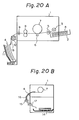
- the prior art reversing mechanism shown in Fig. 20(B) is disadvantageous in that the mechanism is bulky, because it requires a number of components such as the rollers 15 and guides 16 and 17.
- the present invention has been developed in order to overcome the above drawbacks of the prior art and provides a media receiving unit provided with a rotary drum which is disposed in front of a media discharge port of a printing machine and equipped with flexible sheets, in which a paper is reversed by the resiliency of the flexible sheets.
- Figure 1 is a cross-sectional view and Fig. 2 is a front view of an embodiment of the present invention.
- Figure 3 is a view for explaining the operation of the embodiment.
- a rotary drum 27 is connected with a step motor M through a shaft 33.
- the step motor M is fixed to one side of a recording apparatus 1 and driven in response to a rotation control signal sent from a controlling portion (not shown).
- a paper 4 is discharged with a feeding speed of Vo from a discharge roller 9 arranged in the recording apparatus 1.
- the rotary drum 27 shown in Fig. 1 is in a standby state waiting for the paper 4 to be discharged, and at this position, flexible sheets 28-1 and 28-2 made of polyester film and fixed to the rotary drum 27 are opened by an angle 0 to receive the paper 4 therebetween.
- the flexible sheets 28-1 and 28-2 are fixed to the rotary drum 27 by screws 30 through a fitting 29.
- a separation stopper 32 is disposed under the rotary drum 27 in such a manner that the stopper 32 extends on both sides and beyond the circumference of the rotary drum 27 toward a shaft 33.
- the paper 4 is stopped by the stopper 32 and dropped in a stacker 31.
- the recording apparatus 1 is provided with a motor 34 for rotating the discharge roller 9.
- An encoder E for detecting the standby position of the rotary drum 27 is fixed to the shaft 33.
- a detection hole which emits a signal detected by a photosensor F is formed on the encoder E to detect a standby state.
- the paper 4 discharged from the discharge roller 9 is reversed as shown in Figs. 3(A) to (D) and described later.
- a sensor is disposed between a fixing device of the recording apparatus 1 and the discharge roller 9 to detect the passage of a paper. According to a detection signal of the sensor, the rotary drum 27 is rotated after maintaining a standby state for a pre-determined period of time.
- the length of upper flexible sheet 28-1 may be made shorter than that of the lower flexible sheet 28-2 to ensure that the paper 4 slips easily between them.
- the length of the flexible sheet 28-1 is 50 mm to 100 mm.
- the rotary drum 27 is rotated at a circumferential speed of about 0.8Vo which is slower than the discharge speed Vo of paper 4.
- the paper 4 is fed between the flexible sheets 28-1 and 28-2 and bent as shown in Fig. 3(B), and the spring force of flexible sheet 28-2 then reverses the paper 4.
- the length of the lower flexible sheet 28-2 is made 150 mm or more to reverse the paper 4 by the resiliency of the flexible sheet 28-2 irrespective of the unstable nature of the paper 4.
- Figure 3(A) shows a state wherein the paper 4 has just been discharged from the discharge roller 9.
- the rotary drum 27 is in a standby (stop) state just before starting to rotate. This state is set by stopping the motor M according to a detection signal from a position sensor (not shown) which detects the position of the rotary drum 27.
- the flexible sheets 28-1 and 28-2 are arranged in such a manner that the paper 4 is easily introduced therebetween.
- Figure 3(B) shows a state in which the paper 4 has been inserted between the flexible sheets 28-1 and 28-2, and the rotary drum 27 has started to rotate.
- the revolutional speed of the rotary drum 27 is about 0.8 V, which is slower than the discharge speed Vo of the paper 4 discharged from the discharge roller 9. Accordingly, as shown in Fig. 3-(B), the paper 4 is bent between the discharge roller 9 and the rotary drum 27. During this situation, the flexible sheet 28-2 is forced to bent convexly backward by the paper 4.
- Figure 4 is a perspective view showing another embodiment according to the present invention, in which a paper 4 fed between the flexible sheets 28-1 and 28-2 is securely held and completely reversed.
- one end of the flexible sheets (films) 28-2 is fitted to a rotary drum 27'.
- a bar 35 is disposed in such a manner that the bar 35 can move radially relative to and in the vicinity of the periphery of rotary drum 27'. Projections a of the bar 35 engage with grooves b formed on the rotary drum 27'.
- Springs 36 are provided on both sides of the rotary drum 27' to press the bar 35 against the rotary drum 27'.
- the other flexible sheets 28-1 are fixed to an inner side of the bar 35 in such a manner that one end of the flexible sheets 28-1 is in contact with the flexible sheets 28-2.
- the flexible sheets 28-1 may be fixed to the rotary drum 27' instead of the bar 35.
- Shafts 33 extending outwardly from both sides of the rotary drum 27' are rotatably supported by side plates d, and cams 37 are fixed to the side plates d.
- the cams 37 push the bar 35 upward when the flexible sheets 28-1 and 28-2 are located at upper positions to easily receive the paper 4 between the flexible sheets 28-1 and 28-2.
- the bar 35 is lowered due to the actions of cams 37 and securely holds the paper 4.
- Separation stoppers 32 are disposed to separate and release the paper 4 into a stacker 31 located below the rotary drum 27'. Recesses c are formed on the bar 35 to avoid interference of the bar 35 with the stoppers 32.
- Figure 5 shows an arrangement of still another embodiment according to the present invention. Pairs of flexible sheets 128-1 and 128-2, and 128'-1 and 128'-2 are fixed at diametrically opposed positions on a rotary drum 127. The front ends of each pair of flexible sheets are aligned with each other, and a presser bar 135 corresponding to the bar 35 shown in Fig. 4 is provided at each of these front ends.
- a discharge roller 109 is arranged in a printer (not shown) to discharge a printed paper 104 in a direction indicated by an arrow Y.
- the rotary drum 127 is driven by a motor M 1 for rotation in a direction indicated by an arrow Z.
- a bar member 150 for detecting a rotational position of the rotary drum 127 is fixed to the rotary drum 127.
- the paper 104 is held between one of the pairs of flexible sheets, reversed, and then received in a stacker 131.
- the stacker 131 can be reciprocated along an axis of rotation (perpendicular to the plane of Fig. 5) of the rotary drum 127 by a motor M 2 for offset driving.
- the stacker 131 can be moved to sort the printed papers according to the document.
- a photosensor S 1 for detecting papers is disposed adjacent to the discharge roller 109 of the printer, and a photosensor S 2 is used to detect whether or not the stacker 131 is full of paper.
- a microswitch S 3 for detecting a home position detects that one (in this case, 128-1 and 128-2) of the pairs of flexible sheets 128-1 and 128-2, and 128'-1 and 128'-2 of the rotary drum 127 has reached a position (indicated by a continuous line) at which it can for receive the paper 104; microswitch S 4 for detecting a standby position detects that one of the pairs of flexible sheets has reached a position (indicated by a dash line) which is thirty degrees before the home position; switch S 5 detects a normal position of the stacker 131; and a switch S 6 detects an offset position of the stacker 131.
- the rotary drum 127 is in an optional position before it is energized.
- the drum 127 is rotated in a direction indicated by the arrow Z and stopped at the home position if the bar member 150 reaches the switch S 3 .
- the stacker 131 is set to the normal position according to the drive of motor M 2 .
- the sensor S 1 detects a passage of the front end of the paper 104.
- the motor M 1 After the detection of the front end of the paper 104, and after the elapse of time during which the front end of paper 104 reaches a chuck portion (a position where the presser bar 135 is located) of the flexible sheets in the home position, the motor M 1 starts to rotate.
- the timing of the drive of motor M 1 is calculated in advance according to a distance between the sensor S 1 and the chuck portion of flexible sheets and a discharge speed of a paper. On this occasion, the rotation speed of the drum 127 is set to be slower than the discharge speed of a paper 104 caused by the discharge roller 109.
- the rotary drum 127 is rotated by 150° to reach the standby position indicated by a dash line before the sensor S 1 detects an rear end of the paper 104, and the sensor S 4 detects that the standby position is attained and stops the rotation of motor M 1 .
- the rear end of paper 104 is continuously discharged from the discharge roller 109 while the front end of paper 104 is held and stopped.
- the motor M 1 After the detection of the rear end of paper 104 by the sensor S 1 and after the elapse of time during which the rear end of the paper 104 travels from the sensor S 1 to the discharge roller 109, namely, when the paper 104 is released from the discharge roller 109, the motor M 1 is again driven to flip the rear end portion of the paper 104 by the resiliency of lower flexible sheet 128-2 while holding the front end of the paper 104 to reverse the paper 104. In this occasion, the motor M 1 is driven faster than a normal speed.
- the preeser bar 135 is then released by the cam means described before, and the front end of the paper 104 abuts against stoppers in the same manner as in the previous embodiment and is separated from the flexible sheets 128-1 and 128-2 to drop in the stacker 131.
- the other pair of flexible sheets 128'-1 and 128'-2 then comes to the home position that is detected by the sensor S 3 to stop the rotation of motor M 1 until the next paper is discharged.
- the sensor S 1 detects the rear end of paper 104 before the sensor S 4 detects that the drum 127 reaches the standby position. Namely, that before the drum 127 is rotated by 150°, the rear end of paper 104 is discharged from the discharge roller 109.
- the motor M 1 is rotated with an accelerated speed after the detection of the rear end of paper 104 by the sensor S 1 and after the elapse of time during which the rear end of paper 104 travels from the sensor S 1 to the discharge roller 109. In this case, however, the motor M 1 is not stopped at the standby position but continuously rotated until the other pair of flexible sheets comes to the home position.
- the stacker 131 When a stacker offset instruction is generated to sort printed papers for each document unit and pile them in the stacker 131, the stacker 131 is moved by the motor M 2 .
- the sensors S 5 and S 6 detect a position of the stacker 131 to be moved and stop the motor M 2 at a predetermined position. This document collating operation will be described later. If the photosensor S 2 comprising a light emitting element and a photosensitive element detects that the stacker 131 is full of papers, a print termination signal is generated, and the printing operation and the reversing operation are stopped after the paper being discharged from the discharge roller 109 is reversed and received in the stacker 131.
- Figures 6 are overall views of the reversing mechanism having the constitution mentioned above, in which Fig. 6(A) is a front view, Fig. 6(B) a plan view, and Fig. 6(C) a side view.
- Two pairs of flexible sheet pairs 128 and 128' are provided at each of three locations along the rotary drum 127.
- the sheet pairs 128 and 128' comprise upper short flexible sheets 128-1 and 128'-1 respectively, and lower long flexible sheets 128-2 and 128'-2 respectively.
- two presser bars 135 are oppositely provided on the periphery of and along the drum 127.
- each presser bar 135 Both ends of each presser bar 135 are pulled by springs 136 toward a shaft 133 of the drum 127, and the shaft 133 is supported by frames 153.
- Cams 137 similar to the cams shown in Fig. 4 are fixed to the frames 153, and cam followers 154 provided at ends of the presser bars 135 slide on the cams 137.
- the rotary drum 127 is driven by a motor M 1 which is connected to the shaft 133 through a reduction gear 152 and a belt 151.
- Annular grooves 150 are formed on the rotary drum 127 between the positions at which the flexible sheets are fitted. Separation stoppers (not shown) similar to those shown in the previous embodiment are disposed in the annular grooves.
- the shapes of the flexible sheets in the home position are shown in Fig. 6(C).
- the lower long flexible sheet 128-2 is bent along the rotary drum 127 and does not project outward, so that a space for arranging the flexible sheets does not need to be increased even if the length of each flexible sheet is elongated.
- the numeral 155 represents a paper guide frame.
- the side frame 153 has a bent lever 156 which is provided to a shaft 162 to attach the reversing mechanism to a printer.
- the lever 156 is pulled upward by a spring 159 and keeps a horizontal position due to a stopper (not shown).
- a tapered face 157 is formed at the front end of the bent lever 156, and a recess 158 is formed on a back side of the tapered face 157. Rollers 160 slide on a guide rail (not shown) of the printer.
- a connector 161 is provided under the paper guide frame 155. The connector 161 is for connecting power lines, signal lines, etc., of the reversing mechanism with the printer.
- the media receiving unit including such a reversing mechanism is constructed solidly as a single unit and fitted to the printer. To attach the media receiving unit to the printer, the media receiving unit is engaged in a direction indicated by an arrow X shown in Fig. 6(C) with the printer.
- the rollers 160 slide on the guide rail (not shown) of the printer, and the tapered face 157 of the bent lever 156 abuts against a pin (not shown) fixed to the printer.
- the bent lever 156 is then pushed downward by the pin, and the pin enters the recess 158 to be locked therein.
- an end 163 of the lever 156 is pulled to lower the recess 158.
- the connector 161 is aligned with a connector (not shown) of the printer in advance so that they may be coupled together according to the above attaching process.
- FIG. 7 shows a circuit diagram for controlling the reversing operation mentioned above.
- the numeral 1 represents the printer, and 100 the reversing mechanism.
- a circuit 101 for controlling the operation of printer 1 is connected with a microprocessor unit (MPU) 102 for controlling the reversing operation.
- the numerals 103, 105a, and 105b represent driving circuits, and 106 a receiver circuit.
- the MPU 102 incorporates RAMs, ROMs, I/O ports, timers, etc., and controls the operation of the motors M 1 and M 2 according to printing signals and signals from the sensors S 1 to S 6 to reverse the printed papers and control the movement of a stacker.
- FIG. 8 is a perspective view showing still another embodiment according to the present invention.
- the stacker 231 has a modified shape.
- a projection 200 is formed on the stacker 231 and is located in such a manner that it will be positioned within a front half of a paper 204 which is reversed and received in the stacker 231. Due to the projection 200, a rear end of the paper 204, particularly when the paper 204 is long, will not be folded toward a front end thereof after the paper 204 is reversed.
- the paper 204 is flipped backward by an inertial force of the reversing action and dropped along a slanted surface on a back side of the projection 200 so that the reversing and receiving operations of the paper 204 will be securely carried out.
- the projection 200 may be formed in a ridge like shape which does not run in parallel with a rotation shaft 233 of a rotary drum 227 for reversing a paper. This shape of the projection 200 realizes a correct reversing operation with respect to particularly a large size paper.
- the dimensions of stacker shown in Fig. 9 are suitable.
- the numeral 214 represents a separation stopper, 202 a printer, and 209 a discharge roller. Dimensions in the figure are in millimeters.
- FIG. 10 is a view showing another constitution of a stacker-full detection sensor in the media receiving unit according to the present invention.
- a motor M 1 for driving a rotary drum 327 is provided with an encoder 350 for controlling the operation of a motor M 1 .
- the encoder 350 has a plurality of through holes (not shown) arranged concentrically, and a photosensor S 2 comprising a light emitting element 351 and a photosensitive element 352 is disposed corresponding to the positions of the through holes. Since the flexible sheets 328 provided on the rotary drum 327 slide on the top of the paper 304 stacked in a stacker 331, resistance to the rotation the drum 327 will be increased to decrease the rotating speed thereof if the number of paper is increased to heighten the overall height of the papers.
- the rotating speed of the encoder 350 is decreased to decrease the number of through holes (the number of pulses) counted by the sensor S 2 for a predetermined period of time. If the counted number is zero, this signifies that the unit is in a jammed state.
- Figure 11 shows a detection circuit of the embodiment shown in Fig. 10.
- Figure 12 is a time chart showing a normal rotation state, a stack full state, and a jammed state in the circuit shown in Fig. 11.
- the sensor S 2 and a reference pulse generating circuit 410 are connected to a counter 413 via an AND circuit 412.
- a reset circuit 411 is also connected to the counter 413.
- the marks (a), (e), and (h) shown in Fig. 12 represent pulse detection signals generated by the encoder and the sensor S 2 .
- the signal (a) indicated the normal rotation state, (e) the stack full state, and (h) the jammed state.
- the marks (b), (f), and (i) represent reference pulses, and the marks (c), (g), (j) represent the counter outputs corresponding to the above three states respectively.
- the mark (d) represents reset pulses which are inverted signals of the reference pulses.
- Figure 13 shows an engaging state of connectors where the media receiving unit according to the present invention is unitized in one body and attached to a printer.
- a connector 501 is fixed to a frame 500 of the media receiving unit.
- the media receiving unit is fitted to a printer 502 in a direction indicated by an arrow p, and, at the same time, the connector 501 is coupled with a connector 503 provided on the printer 502.
- the numeral 504 represents a stacker, 505 a rotary drum, and 506 a discharge roller.
- FIG 14 shows still another embodiment according to the present invention.
- printed papers are sorted for every document and accumulated in a tray (stacker).
- a tray 600 is movable in directions indicated by an arrow Q in parallel with a rotation shaft 602 of a rotary drum 601 so that printed papers 603 to be discharged will be piled up in the tray 600 at predetermined positions.
- Figure 15 shows the constitution of a tray moving mechanism.
- a support base 625 and a back plate 626 are assembled in one body, and a guide pin 627 and a rack 628 are provided on the back side of tray 600. If the tray 600 is made of resin, the guide pin 627 and the rack 628 may be formed integrally therewith.
- On the support base 625 a rail 629 for sliding the tray 600 and holes 630 and 631 for horizontal positioning are provided.
- a gap between the width of rack 628 and the width of hole 630 is 0.2 to 0.5 mm.
- the back plate 626 is attached to the reverse side of support base 625, and a connector 620 fitted to the back plate 626 engages with a connector on the printer side.
- the connector 620 is connected to a control circuit 632, which cause a motor M 2 633 to rotate to move the tray 600 by the engagement between a pinion 634 and the rack 628.
- the numerals 635 and 636 represent fitting screws.
- FIGs 16(A) and (B) describe the reciprocating movement of tray 600.
- a paper 603 discharged from a discharge port 613 of a recording apparatus 612 is reversed by a rotary drum 601 of the reversing mechanism, and is piled up in the tray 600.
- the motor 633 is driven according to a signal from the apparatus 612 to move the tray 600 so that the papers will be sorted for each document and piled up in the tray 600.
- the movement of tray 600 is detected by limit switches S 5 and S 6 similar to the sensors S 5 and S 6 described in the embodiment shown in Fig. 5.
- FIG. 17 shows still another embodiment according to the present invention.
- a media receiving mechanism of the embodiment comprises a photosensor DS for detecting a medium 701 discharged from a discharge roller 702 of a printer 710; a cam 706 fitted to a rotation shaft 707 of a drum 703; and a pair of cam switches SW1 and SW2 which are turned ON and OFF by the cam 706.
- a standby position T is set in front of (i.e., in the figure, on the left side of) a stopper 705 for separating discharged papers.
- the modes of operation of the drum 703 and chuck 704 are decided after a front end of the medium 701 reaches a point just before the stopper 705.
- the drum 703 continues to rotate irrespective of the standby position T, and the chuck 704 releases the medium 701.
- the drum 703 is stopped temporarily at the standby position T, and the chuck 704 continues to hold the medium 701 until the medium 701 is completely discharged.
- the front end of medium 701 is kept at the point just before the stopper 705 until the rear end of medium 701 is discharged, and once the discharge is completed, the front end of medium 701 is released so that a misreversal can not occur.
- Fig. 18 is an operation timing chart
- Fig. 19 which shows an example of a circuit of the embodiment. Marks used in the following description correspond to the marks shown in Figs. 17 to 19.
Landscapes
- Engineering & Computer Science (AREA)
- Mechanical Engineering (AREA)
- Pile Receivers (AREA)
- Delivering By Means Of Belts And Rollers (AREA)
Claims (15)
dadurch gekennzeichnet, daß:- das rotierende Teil mit einer niedrigeren Geschwindigkeit als der Geschwindigkeit rotiert wird, mit welcher das genannte Medium von der Medienverarbeitungsvorrichtung abgegeben wird, um so zu verursachen, daß das genannte Medium von dem rotierenden Teil nach außen gebogen wird; und daß dann, wenn das hintere Ende des genannten Mediums von der Medienverarbeitungsvorrichtung freigegeben wird, die flexiblen Blätter das hintere Ende des Mediums vorschnellen, unter Verwendung einer elastischen Rückstellkraft der flexiblen Blätter, während das vordere Ende des genannten Mediums gehalten wird, um das Medium umzukehren und das Medium in die genannte Medienempfangseinrichtung zu plazieren.
Applications Claiming Priority (10)
| Application Number | Priority Date | Filing Date | Title |
|---|---|---|---|
| JP91513/85 | 1985-04-27 | ||
| JP9151385A JPS61254462A (ja) | 1985-04-27 | 1985-04-27 | 媒体収容装置 |
| JP96965/85 | 1985-05-08 | ||
| JP9696585A JPS61257859A (ja) | 1985-05-08 | 1985-05-08 | 媒体収容装置 |
| JP118016/85 | 1985-05-31 | ||
| JP11801685A JPS61277547A (ja) | 1985-05-31 | 1985-05-31 | 媒体収容装置の堆積状態検出方法 |
| JP60205612A JPS6265879A (ja) | 1985-09-18 | 1985-09-18 | 媒体収容装置 |
| JP205612/85 | 1985-09-18 | ||
| JP28828385A JPS62146866A (ja) | 1985-12-20 | 1985-12-20 | 媒体収容機構 |
| JP288283/85 | 1985-12-20 |
Publications (3)
| Publication Number | Publication Date |
|---|---|
| EP0200481A2 EP0200481A2 (de) | 1986-11-05 |
| EP0200481A3 EP0200481A3 (en) | 1988-06-22 |
| EP0200481B1 true EP0200481B1 (de) | 1992-07-01 |
Family
ID=27525548
Family Applications (1)
| Application Number | Title | Priority Date | Filing Date |
|---|---|---|---|
| EP86303103A Expired EP0200481B1 (de) | 1985-04-27 | 1986-04-24 | Vorrichtung zum Aufnehmen von Dokumenten |
Country Status (4)
| Country | Link |
|---|---|
| US (2) | US4770405A (de) |
| EP (1) | EP0200481B1 (de) |
| CA (1) | CA1276656C (de) |
| DE (1) | DE3685845T2 (de) |
Families Citing this family (17)
| Publication number | Priority date | Publication date | Assignee | Title |
|---|---|---|---|---|
| DE3844324A1 (de) * | 1988-12-27 | 1990-06-28 | Mannesmann Ag | Druckstation mit ausgabevorrichtung fuer einzelblaetter |
| US5098080A (en) * | 1990-12-19 | 1992-03-24 | Xerox Corporation | Ski jump stack height sensor |
| US5261655A (en) * | 1992-12-28 | 1993-11-16 | Xerox Corporation | Disk stacker with intermittent corrugation assistance for small sheets |
| JP2717028B2 (ja) * | 1993-04-28 | 1998-02-18 | ケーニッヒ ウント バウエル−アルバート アクチエンゲゼルシャフト | 折り装置における折り丁の位置正しい受け渡し方法及び装置 |
| US5961115A (en) * | 1997-05-09 | 1999-10-05 | Lexmark International Inc. | Method and system of sensing an output level of an output stack of print media in an image forming apparatus |
| US5913513A (en) * | 1997-05-22 | 1999-06-22 | Troy Systems, Inc. | Add-on modular paper mover |
| FR2773548B1 (fr) * | 1998-01-15 | 2000-04-07 | Canon Kk | Dispositif de traitement de feuilles |
| DE10059005A1 (de) * | 2000-11-28 | 2002-05-29 | Nexpress Solutions Llc | Blattablagevorrichtung |
| DE10126893A1 (de) * | 2001-06-01 | 2002-12-12 | Nexpress Solutions Llc | Ablageeinrichtung einer Druckmaschine |
| US7183730B2 (en) * | 2003-05-15 | 2007-02-27 | Hewlett-Packard Development Company, L.P. | Method and apparatus for receiving and manipulating sheet material |
| US7591468B2 (en) * | 2007-07-02 | 2009-09-22 | Xerox Corporation | Low noise compile paddles |
| JP2009091064A (ja) * | 2007-10-04 | 2009-04-30 | Seiko Instruments Inc | プリンタおよび発行装置 |
| US8496244B2 (en) * | 2010-07-28 | 2013-07-30 | Kabushiki Kaisha Toshiba | Sheet processing apparatus and sheet processing method |
| JP5556826B2 (ja) * | 2012-01-25 | 2014-07-23 | コニカミノルタ株式会社 | 用紙排出装置 |
| US9199818B2 (en) * | 2014-04-02 | 2015-12-01 | Xerox Corporation | Paddle wheel compiler |
| WO2020059078A1 (ja) * | 2018-09-20 | 2020-03-26 | 株式会社Pfu | 媒体反転排出装置 |
| EP4011813B1 (de) | 2020-12-08 | 2023-09-13 | Canon Production Printing Holding B.V. | Bogenstapler mit einer bogenwendevorrichtung und einer stützvorrichtung |
Family Cites Families (14)
| Publication number | Priority date | Publication date | Assignee | Title |
|---|---|---|---|---|
| US1266741A (en) * | 1913-06-16 | 1918-05-21 | Wood Newspaper Mach Corp | Method of delivering folded sheets. |
| US1266742A (en) * | 1917-12-10 | 1918-05-21 | Wood Newspaper Mach Corp | Apparatus for delivering folded sheets. |
| US1363031A (en) * | 1918-06-17 | 1920-12-21 | Wood Newspaper Mach Corp | Method of delivering sheets and apparatus therefor |
| US1637170A (en) * | 1926-06-14 | 1927-07-26 | Hoe & Co R | Associating and delivery mechanism |
| US3010717A (en) * | 1959-06-17 | 1961-11-28 | Western Union Telegraph Co | Message accumulator for recorders |
| DE2309075A1 (de) * | 1973-02-23 | 1974-08-29 | Agfa Gevaert Ag | Kopiergeraet |
| JPS6141097Y2 (de) * | 1978-04-15 | 1986-11-22 | ||
| US4228997A (en) * | 1978-06-23 | 1980-10-21 | Eastman Kodak Company | Stacking machine |
| US4252309A (en) * | 1979-06-29 | 1981-02-24 | International Business Machines Corporation | Document sheet flipper |
| US4431177A (en) * | 1980-08-29 | 1984-02-14 | Xerox Corporation | Sheet offsetting and registering apparatus |
| US4449812A (en) * | 1980-10-17 | 1984-05-22 | Canon Kabushiki Kaisha | Paper leaf handling apparatus |
| JPS59149264A (ja) * | 1983-02-10 | 1984-08-27 | Fuji Xerox Co Ltd | ソ−テイング装置 |
| JPS60238856A (ja) * | 1984-05-11 | 1985-11-27 | Toshiba Corp | 集積装置 |
| DE3429856C1 (de) * | 1984-08-14 | 1986-02-06 | Mannesmann Kienzle GmbH, 7730 Villingen-Schwenningen | Sortiermodul fuer die Belegsortierung |
-
1986
- 1986-04-23 CA CA000507388A patent/CA1276656C/en not_active Expired - Lifetime
- 1986-04-24 DE DE8686303103T patent/DE3685845T2/de not_active Expired - Fee Related
- 1986-04-24 EP EP86303103A patent/EP0200481B1/de not_active Expired
- 1986-04-25 US US06/855,651 patent/US4770405A/en not_active Expired - Fee Related
-
1988
- 1988-09-09 US US07/242,388 patent/US4969641A/en not_active Expired - Lifetime
Also Published As
| Publication number | Publication date |
|---|---|
| US4969641A (en) | 1990-11-13 |
| DE3685845T2 (de) | 1993-02-11 |
| CA1276656C (en) | 1990-11-20 |
| EP0200481A2 (de) | 1986-11-05 |
| DE3685845D1 (de) | 1992-08-06 |
| US4770405A (en) | 1988-09-13 |
| EP0200481A3 (en) | 1988-06-22 |
Similar Documents
| Publication | Publication Date | Title |
|---|---|---|
| EP0200481B1 (de) | Vorrichtung zum Aufnehmen von Dokumenten | |
| EP1225146B1 (de) | Vorrichtung zum Ausrichten von einem bogenförmigen Medium | |
| US4721297A (en) | Sheet feeder | |
| US20040251608A1 (en) | Sheet stacking apparatus and image forming apparatus equipped with the same | |
| JPH0853252A (ja) | ディスクタイプシートスタック装置及びディスクタイプシートスタック装置を含む静電写真印刷機 | |
| CA1217789A (en) | Single-sheet separating apparatus, particularly for use with office machines | |
| GB2087845A (en) | Stripping sheets | |
| JPH0327030B2 (de) | ||
| JPH08225212A (ja) | 用紙出力装置 | |
| CA1289584C (en) | Media receiving unit | |
| EP0046893B1 (de) | Zuführrad für einen Blattzuführungsapparat und es enthaltender Blattzuführungsapparat | |
| JP2614296B2 (ja) | シート自動供給装置 | |
| JPH0537960Y2 (de) | ||
| JPH0620956B2 (ja) | 給紙装置 | |
| US5293204A (en) | Copier with a superposed-sheet separation mechanism | |
| JPH066457B2 (ja) | 自動原稿送り装置 | |
| JP2867023B2 (ja) | シート搬送装置 | |
| CA2053555C (en) | Copier with a superposed-sheet separation mechanism | |
| JP2997933B2 (ja) | シ―ト搬送装置 | |
| JPH0714288Y2 (ja) | シート搬送装置 | |
| KR930010161B1 (ko) | 원고자동 순환급송장치 | |
| JP2514520Y2 (ja) | 給紙装置 | |
| JP3273447B2 (ja) | 用紙揃え装置 | |
| JP2000038248A (ja) | 印刷装置 | |
| JPS62244032A (ja) | 自動原稿送り装置 |
Legal Events
| Date | Code | Title | Description |
|---|---|---|---|
| PUAI | Public reference made under article 153(3) epc to a published international application that has entered the european phase |
Free format text: ORIGINAL CODE: 0009012 |
|
| AK | Designated contracting states |
Kind code of ref document: A2 Designated state(s): DE FR GB IT |
|
| PUAL | Search report despatched |
Free format text: ORIGINAL CODE: 0009013 |
|
| AK | Designated contracting states |
Kind code of ref document: A3 Designated state(s): DE FR GB IT |
|
| 17P | Request for examination filed |
Effective date: 19880823 |
|
| 17Q | First examination report despatched |
Effective date: 19900720 |
|
| ITF | It: translation for a ep patent filed | ||
| GRAA | (expected) grant |
Free format text: ORIGINAL CODE: 0009210 |
|
| PGFP | Annual fee paid to national office [announced via postgrant information from national office to epo] |
Ref country code: FR Payment date: 19920629 Year of fee payment: 8 |
|
| AK | Designated contracting states |
Kind code of ref document: B1 Designated state(s): DE FR GB IT |
|
| REF | Corresponds to: |
Ref document number: 3685845 Country of ref document: DE Date of ref document: 19920806 |
|
| ET | Fr: translation filed | ||
| PGFP | Annual fee paid to national office [announced via postgrant information from national office to epo] |
Ref country code: GB Payment date: 19930415 Year of fee payment: 8 |
|
| PLBE | No opposition filed within time limit |
Free format text: ORIGINAL CODE: 0009261 |
|
| STAA | Information on the status of an ep patent application or granted ep patent |
Free format text: STATUS: NO OPPOSITION FILED WITHIN TIME LIMIT |
|
| 26N | No opposition filed | ||
| PG25 | Lapsed in a contracting state [announced via postgrant information from national office to epo] |
Ref country code: GB Effective date: 19940424 |
|
| GBPC | Gb: european patent ceased through non-payment of renewal fee |
Effective date: 19940424 |
|
| PG25 | Lapsed in a contracting state [announced via postgrant information from national office to epo] |
Ref country code: FR Effective date: 19941229 |
|
| REG | Reference to a national code |
Ref country code: FR Ref legal event code: ST |
|
| PGFP | Annual fee paid to national office [announced via postgrant information from national office to epo] |
Ref country code: DE Payment date: 19990430 Year of fee payment: 14 |
|
| PG25 | Lapsed in a contracting state [announced via postgrant information from national office to epo] |
Ref country code: DE Free format text: LAPSE BECAUSE OF NON-PAYMENT OF DUE FEES Effective date: 20010201 |
|
| PG25 | Lapsed in a contracting state [announced via postgrant information from national office to epo] |
Ref country code: IT Free format text: LAPSE BECAUSE OF NON-PAYMENT OF DUE FEES;WARNING: LAPSES OF ITALIAN PATENTS WITH EFFECTIVE DATE BEFORE 2007 MAY HAVE OCCURRED AT ANY TIME BEFORE 2007. THE CORRECT EFFECTIVE DATE MAY BE DIFFERENT FROM THE ONE RECORDED. Effective date: 20050424 |