EP0199590A2 - Laserrobotersystem - Google Patents
Laserrobotersystem Download PDFInfo
- Publication number
- EP0199590A2 EP0199590A2 EP86303046A EP86303046A EP0199590A2 EP 0199590 A2 EP0199590 A2 EP 0199590A2 EP 86303046 A EP86303046 A EP 86303046A EP 86303046 A EP86303046 A EP 86303046A EP 0199590 A2 EP0199590 A2 EP 0199590A2
- Authority
- EP
- European Patent Office
- Prior art keywords
- laser
- robot
- axis
- work cell
- laser beam
- Prior art date
- Legal status (The legal status is an assumption and is not a legal conclusion. Google has not performed a legal analysis and makes no representation as to the accuracy of the status listed.)
- Withdrawn
Links
Images


Classifications
-
- F—MECHANICAL ENGINEERING; LIGHTING; HEATING; WEAPONS; BLASTING
- F16—ENGINEERING ELEMENTS AND UNITS; GENERAL MEASURES FOR PRODUCING AND MAINTAINING EFFECTIVE FUNCTIONING OF MACHINES OR INSTALLATIONS; THERMAL INSULATION IN GENERAL
- F16P—SAFETY DEVICES IN GENERAL; SAFETY DEVICES FOR PRESSES
- F16P3/00—Safety devices acting in conjunction with the control or operation of a machine; Control arrangements requiring the simultaneous use of two or more parts of the body
- F16P3/08—Safety devices acting in conjunction with the control or operation of a machine; Control arrangements requiring the simultaneous use of two or more parts of the body in connection with the locking of doors, covers, guards, or like members giving access to moving machine parts
-
- B—PERFORMING OPERATIONS; TRANSPORTING
- B23—MACHINE TOOLS; METAL-WORKING NOT OTHERWISE PROVIDED FOR
- B23K—SOLDERING OR UNSOLDERING; WELDING; CLADDING OR PLATING BY SOLDERING OR WELDING; CUTTING BY APPLYING HEAT LOCALLY, e.g. FLAME CUTTING; WORKING BY LASER BEAM
- B23K26/00—Working by laser beam, e.g. welding, cutting or boring
- B23K26/08—Devices involving relative movement between laser beam and workpiece
- B23K26/0823—Devices involving rotation of the workpiece
-
- B—PERFORMING OPERATIONS; TRANSPORTING
- B23—MACHINE TOOLS; METAL-WORKING NOT OTHERWISE PROVIDED FOR
- B23K—SOLDERING OR UNSOLDERING; WELDING; CLADDING OR PLATING BY SOLDERING OR WELDING; CUTTING BY APPLYING HEAT LOCALLY, e.g. FLAME CUTTING; WORKING BY LASER BEAM
- B23K26/00—Working by laser beam, e.g. welding, cutting or boring
- B23K26/08—Devices involving relative movement between laser beam and workpiece
- B23K26/0869—Devices involving movement of the laser head in at least one axial direction
- B23K26/0876—Devices involving movement of the laser head in at least one axial direction in at least two axial directions
- B23K26/0884—Devices involving movement of the laser head in at least one axial direction in at least two axial directions in at least in three axial directions, e.g. manipulators, robots
-
- B—PERFORMING OPERATIONS; TRANSPORTING
- B23—MACHINE TOOLS; METAL-WORKING NOT OTHERWISE PROVIDED FOR
- B23K—SOLDERING OR UNSOLDERING; WELDING; CLADDING OR PLATING BY SOLDERING OR WELDING; CUTTING BY APPLYING HEAT LOCALLY, e.g. FLAME CUTTING; WORKING BY LASER BEAM
- B23K26/00—Working by laser beam, e.g. welding, cutting or boring
- B23K26/70—Auxiliary operations or equipment
- B23K26/702—Auxiliary equipment
- B23K26/706—Protective screens
-
- B—PERFORMING OPERATIONS; TRANSPORTING
- B25—HAND TOOLS; PORTABLE POWER-DRIVEN TOOLS; MANIPULATORS
- B25J—MANIPULATORS; CHAMBERS PROVIDED WITH MANIPULATION DEVICES
- B25J19/00—Accessories fitted to manipulators, e.g. for monitoring, for viewing; Safety devices combined with or specially adapted for use in connection with manipulators
- B25J19/0025—Means for supplying energy to the end effector
- B25J19/0029—Means for supplying energy to the end effector arranged within the different robot elements
- B25J19/0037—Means for supplying energy to the end effector arranged within the different robot elements comprising a light beam pathway, e.g. laser
-
- B—PERFORMING OPERATIONS; TRANSPORTING
- B25—HAND TOOLS; PORTABLE POWER-DRIVEN TOOLS; MANIPULATORS
- B25J—MANIPULATORS; CHAMBERS PROVIDED WITH MANIPULATION DEVICES
- B25J19/00—Accessories fitted to manipulators, e.g. for monitoring, for viewing; Safety devices combined with or specially adapted for use in connection with manipulators
- B25J19/0054—Cooling means
-
- B—PERFORMING OPERATIONS; TRANSPORTING
- B25—HAND TOOLS; PORTABLE POWER-DRIVEN TOOLS; MANIPULATORS
- B25J—MANIPULATORS; CHAMBERS PROVIDED WITH MANIPULATION DEVICES
- B25J19/00—Accessories fitted to manipulators, e.g. for monitoring, for viewing; Safety devices combined with or specially adapted for use in connection with manipulators
- B25J19/06—Safety devices
-
- F—MECHANICAL ENGINEERING; LIGHTING; HEATING; WEAPONS; BLASTING
- F16—ENGINEERING ELEMENTS AND UNITS; GENERAL MEASURES FOR PRODUCING AND MAINTAINING EFFECTIVE FUNCTIONING OF MACHINES OR INSTALLATIONS; THERMAL INSULATION IN GENERAL
- F16P—SAFETY DEVICES IN GENERAL; SAFETY DEVICES FOR PRESSES
- F16P1/00—Safety devices independent of the control and operation of any machine
- F16P1/06—Safety devices independent of the control and operation of any machine specially designed for welding
Definitions
- This invention generally relates to automated manufacturing apparatus, and systems which use such apparatus. More particularly, this invention is directed to an integrated type laser-robotic work cell which includes peripheral equipment necessary to form a functional system.
- High powered lasers are ideally suited to be used as a source of heat in various material processing applications which include the vaporization of materials, and drilling and cutting operations. Lasers are also applicable to procedures, such as welding or surface cladding of materials, that is to say processes and procedures which require the melting of materials. Lasers can also be effectively used for temperature control in hardening and annealing operations.
- the thermal effects which are experienced by materials when exposed to laser beams are primarily dependent on the intensity of laser energy, the absorptivity of the material, and the length of time during which the material is exposed to the laser beam. Precise control over these parameters determines the resulting change in the phase or the state of the material.
- the area of the workpiece to be processed is oriented in such a way that it is nearly normal to the laser beam with the beam impinging perpendicularly on its surface. Such an arrangement optimizes the absorptivity of the material and facilitates its heating.
- the laser and the workpiece are caused to move relative to each other. This relative motion can be accomplished in two ways.
- the beam can be traversed over a stationary workpiece.
- the workpiece can be manipulated under a fixed laser beam.
- the former method requires that the laser beam be moved either by mounting the laser on a movable device or by directing the beam from a fixed laser to the workpiece by use of a movable optical system.
- European preliminary patent publication No. 0122146 entitled General Purpose Orthogonal Axes Manipulator System by Daniel P. Soroka et al. which is assigned to the assignee of the present invention, discloses an overhead gantry style robot with a large rectangular working envelope. This robot permits programming in Cartesian coordinates as contrasted with the more complicated polar coordinates.
- This gantry robot design provides a rigid manipulator that supports machine tool-type interpolaton moves, high accuracy and repeatability while permitting robotic-type velocity and dexterity.
- the gantry design provides for an overhead X axis assembly supported by vertical structural members.
- the Y axis assembly extends as an arm from the X axis assembly and further supports a vertical Z axis assembly.
- a mounting surface on the Z axis assembly is designed to accommodate a multiple axis rotary wrist to which an appropriate end effector can be attached.
- This end effector can be a gripper, welding torch, or as will be described herein, a YAG laser or the delivery point of a laser delivery system.
- U.K. Patent publication No. 2134071 (U.S. Patent No. 4,539,462) which is entitled Robotic Laser Beam Delivery Apparatus by Daniel J. Plankenhorn which is assigned to the assignee of the present invention, discloses a light beam directing apparatus which permits a reflected beam of light, such as a laser, to be directed in a path which comprises a plurality of straight segments. Each segment of the beam is associated with a segment of a robots axis in a fixed spatial relationship.
- the aforedescribed patent publications describe only a portion of a total system that is utilized according to this invention to provide a complete work cell.
- Known prior art elements still lack structural elements to perform several additional functions such as, for example, programmable control, air filtering/ drying, chilling of coolant, safety enclosure, suitable exhaust system.
- the present invention describes several important items which when used in combination with the gantry-type robot and laser beam delivery system provides a complete work cell. is in communication with the optical joints in order to maintain the temperature of the reflective optical joints within predetermined parameters.
- An exhaust system with ducting means disposed proximate the end of the Z-axis or tooling disposed thereon provides a means whereby toxic fumes generated by metal working processes can be withdrawn from the work area.
- a variety of precision tables and other fixturing can also be provided in combination with the work cell of this invention to enhance the performance and flexibility thereof.
- a robot manipulator as described above can be used in combination with a laser package such as a YAG laser, wave guide laser, bar code reader, etc.
- a laser package such as a YAG laser, wave guide laser, bar code reader, etc.
- a combination within the work cell would of course eliminate the need for the laser beam delivery system and its attendant systems.
- the safety enclosure system as well as the tooling and precision tables and fixtures can remain an integral portion of the work cell according to this alternative embodiment.
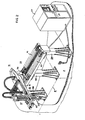
- a complete, integrated robot-laser work cell system is isometrically presented in Figure 1 and generally indicated by the reference character 11.
- the robot-laser system 11 includes an orthogonal axis manipulator system 13 to which is coupled a laser system 15 by means of a laser beam delivery system 17.
- This system 11 also includes an exhaust system at 19, a safety enclosure means 21 and a precision table or other fixture as at 23.
- a coolant chiller for the optics used in the laser beam delivery system 17 is indicated at 25 and the programmable controller by which the orthogonal axis manipulator is directed is indicated at 27.
- the end of arm tooling or end effector utilized in combination with the laser beam delivery system 17 and the orthogonal axis manipulator 13 is an application dependent variable. Accordingly, the desired work to be effected by the laser-robot system of this invention will dictate the specific tooling to be utilized with the robot as well as the type of wrist selected which depends in part, upon the number of degrees of freedom desired within the work envelope.
- FIG. 2 there is illustrated a manipulator system 13 comprising three orthogonal axes assemblies consisting of the X axis assembly 33, the Y axis assembly 35, and the Z axis assembly 37.
- An optional multiple axis rotary wrist mechanism 29 is mechanically secured to the axis assembly 37 to accommodate an end effector T which as described above could typically be a gripper, a welding torch, etc., for use in combination with the laser beam delivery system 17 (of Figure 1).
- the operative combination of the X, Y and Z axes assembly is supported in a gantry-type configuration by the vertical support members SM which are secured to the floor F of the working facility.
- Machine tool-type control of the operation of the manipulator system 13 is implemented by a conventional numerical control console 27 such as the PRODUCER TM CNC System which is available from the Westinghouse Electric Corporation.
- the orthogonal axis machine tool-type configuration of the X, Y and Z axes assemblies elevated in the gantry configuration results in an optimized working envelope corresponding to the rectangular volume work zone Z.
- This gantry configuration of an orthogonal axis manipulator system significantly reduces the number of wrist articulations required to implement the desired work process, and further reduces requirements for auxiliary devices such as rotary tables.
- Pulse width modulated drive for the close loop DC servo motor arrangements of each axis assembly is provided through the use of conventional drive circuitry located in the drive cabinet portion on the robot control 27.
- the direct coupled DC servo motor arrangements include a motor-tachometer package and a resolver or an encoder. The tachometer provides speed feedback information to the control console CS while the resolver supplies the control console CS with position feedback information directly from the drive motor. This produces a highly stable servo response.
- the X axis assembly 33 as shown in Figure 2 consists of a closed cell type of construction which minimizes the torsional deflection of the X axis carriage 39 as it travels along the X axis guidance system, thereby providing the desired system accuracy and repeatability.
- the X axis guidance system, or way system includes two, 3-inch diameter ground guide rails 41 and 43 which provide maximum rigidity and stiffness for the torsional-type bending modes.
- the dual rail way system which is supported by the members SM further assures a smooth low friction travel of the X axis carriage in response to the closed loop DC servo control.
- the X axis carriage 39 is coupled to the guide rails 41 and 43 by linear bearings which are preloaded and sealed in the housings 47 to protect the bearings from dirt.
- the mechanical drive for the X axis assembly is a rack and pinion mechanism consisting of a rack and pinion shaft which is direct coupled to a DC motor tachometer package.
- the Y axis assembly 35 functions as an arm extending perpendicularly from the X axis assembly 33.
- the Y axis assembly includes a support member assembly 61 and a double rail way arrangement which minimizes the stresses and rotational deflections during the Y axis travel of the Y axis carriage as well as during the positioning of the Z axis assembly 37 within the work zone Z.
- the guide rails are protected by bellows covers 65.
- the Z axis assembly 37 employs a ball screw mechanism consisting of a ball screw and a fixed nut in combination with a way mechanism consisting of guide rails to transport the Z axis carriage in response to the drive motor-tachometer package motor.
- the dual rail way mechanism functions similarly to that described above with respect to the X and Y axis. Additional unique features incorporated into the orthogonal axis manipulator described hereinabove are disclosed in U.S. Patent Application Serial No. 485,076 which is assigned to the assignee of the present invention and which is incorporated herein by reference as if fully set forth.
- the laser beam delivery system used in this work cell in its simplest form comprises a series of joints which are attached to a support member or arm defining one axis of movement of the robotic system 13.
- the configuration shown in Figure 3 illustrates an embodiment of the laser beam delivery system utilized in combination with the Series 6000 orthogonal axis manipulator 13. This configuration permits synchronous movement in conjunction with the displacement of the various arms defining the axes of the manipulator 13. As long as the incident light beam lies on the axis of motion A of the optical joint, the laser beam will be delivered and the laser beam delivery system will function properly. It should be appreciated that this axis of motion can be one of either axial or rotational movement or a combination thereof.
- Figure 4 comprises two optical joints 140 and 142, which are disposed in axially displaceable relationship with each other.
- the optical joints 140 and 142 can be seen to direct the beam along the Y axis of the orthogonal axis manipulator 13.
- joint 142 can move either toward or away from joint 140 along its axis of motion A in the direction shown by the arrow 144.
- joint 142 can alternatively assume the positions shown by reference numerals 142 and 142', inter alia.
- joint 142 is rigidly attached to a tubular member 158 and tubular member 158 is associated in sliding relation with tubular member 156. As these two slidably associated members move axially with respect to each other in the direction shown by arrow 144, joint 142 moves either toward joint 140 or away from it.
- the resulting reflecting light beam 162 passes from the reflective member 160, out of the optical joint 142 and through the tubular member 164 in a direction which is at an angle of 90° to the light beam 154. Therefore, as the optical joint 142 moves in this axial relationship with optical joint 140, the resulting deflected light beam 162 will move in a linear path. It should further be understood that the joint 142 which is shown in dashed line in Figure 3 and its associated components which are designated with similar primed reference numerals represent an alternative position of this optical joint.
- the system described herein can be used with any of a variety of commercially available lasers. However, the actual construction of this system incorporated an Everlast EFA 51 CO Z laser manufactured by Coherent Inc.
- the axial-flow laser has a power rating of 1250 watts.
- Various laser systems and types may be readily interfaced with the Series 6000 robot described herein. Since laser selection is highly application dependent, this interface flexibility assures that the proper manufacturing requirements are satisfied during the cell system configuraton.
- a multiwatt CO. laser can be installed with the laser head mounted next to the robot manipulator and the beam path directed to a 3- axes programmed sequence of positions within the working envelope as shown in Figure 1.
- a wave guide laser, bar code reader, a 400 watt YAG laser head or laser package of a similar size can be mounted on the vertical axis of the robot manipulator and moved in any 5-axis sequence to any location within the working envelope.
- the beam transmission hardware, i.e. laser beam delivery system 17 would thus be eliminated.
- the application dependency of the selection of the laser used in conjunction with the robot manipulator would determine the proper laser selection.
- the system of Figure 1 also provides an air filtration drying and regulating system at 20 shown in Figure 1.
- a suitable system is commercially available in Balstron Filter Products, "Air Dryer Model 75".
- the reflective surfaces within the optical joints i.e., optical joint 140 in Figure 3
- the reflective surfaces within the optical joints is a highly reflective material. Dust and condensation on these reflective surfaces has been identified as a potentially major problem in a laser beam delivery system such as described herein.
- the presence of dust and condensation within the laser beam delivery system 17 can cause beam blooming and will render the system inoperative. While several options are available for alleviating this problem, as will be readily appreciated, two of them offer both system interruption possibilities and on-going unnecessary expenses. It is possible, of course, to change the reflective material or periodically change the reflective members. To do so would require a system shutdown.
- a dry air filtration system be utilized because it is, over the long term, the most cost effective and efficient method for ensuring that the mirrors remain substantially free of dust and condensation during the system's operations and a desired environment is maintained within the delivery system.
- the previously identified commercially available filtration system also includes a bed of absorbent granules which remove such constituents as water vapor, carbon dioxide, sulfur hexafluoride, etc., which cause thermal beam blooming within the laser beam delivery system.
- the exhaust system 19 shown in Figure 1 includes a conduit system 19' which terminates proximate the laser beam delivery point 30 of the manipulator 13. It should be appreciated that do to the generic material processing nature of this system, some materials will emit toxic fumes during laser cutting and cladding processes. Accordingly, this exhaust system 19 provides a pickup nozzle disposed proximate the wrist and directed toward the source of the fumes. Means are provided in association with the pickup nozzle to generate the negative pressure necessary to draw the fumes from the work area for ultimate discharge and/or filtration. This system significantly reduces the toxic fumes in the work area.
- Another key feature of the laser-robot system 11 is the safety enclosure generally indicated by the reference character 21 in Figure 1. Characteristics and dangers of laser beams have prompted the need for a safety enclosure within which the work cell functions. It has been found that a plexiglass enclosure surrounding the working envelope provides a substantial margin of safety. The plexiglass enclosure, due to the characteristics of plexiglass will serve a multiplicity of purposes. For example, if plexiglass is hit by the laser when, for example, when one is using a 10.6 micron C02 laser, smoke emits prior to bum-through and serves as an early warning signal to any individuals proximate the work cell. Additionally, plexiglass allows the operator to view the system operation with decreased risk of harm.
- the plexiglass can serve as a line of defense against unauthorized personnel entering the work envelope.
- the plexiglass can be provided with a series of stationary panels as at 173 supported by frame work members 175.
- a sliding door arrangement 177 and 179 supported by track member 181 can allow ease of entry and exit from the work cell by work personnel.
- an innerlock system can be provided as at 183 which indicates to the robot controller that the sliding plexiglass doors are opened and that the laser operated functions should be terminated until an operator can investigate the interruption. It should further be appreciated that other type lasers might require different material than plexiglass for similar protection.
- a robot control 27 is provided in the system for use in combination with the aforedescribed Series 6000 robot.
- the system is available with two control configurations, the Unimation VAL 11 and an optional CNC.
- the VAL 11 control uses a high level, highly structured computer language based upon intuitive English commands which are easy to learn, use and execute.
- the CNC control is programmed using standard machine tool programming language commands via an integral CRT and membrane keyboard.
- Post processors are available to allow off-line or CAD programming in APT or APT-like languages.
- memory storage on paper tape, floppy disc, etc. is available.
- There are various alternative methods for facilitating the preparation or modification of the robot operating program The forefront of advanced technology CAE/CAD/CAM is available.
- the interactive graphics of the CAD computer assists in all or part of the design, configuration, and program.
- a three dimensional product is displayed on the CRT and the laser motion as computer programmed is visually checked to verify that the program is functioning exactly as desired.
- This program is then post processed into robot machine language, transmitted by direct numerical control link to the robot computer and executed.
- a program can be manually written and post processed into the robot machine language. At higher levels of automation these characteristics and be effectively utilized to provide total FMS capability.
- FIG. 4 an alternative arrangement using a YAG laser mounted onto the Z-axis arm of the manipulator 13 is shown.
- the YAG laser is shown for illustrative purposes only. It is to be appreciated that a bar code reader, wave guide laser or laser package of similar dimensions can be mounted on the wrist or Z axis arm of the manipulator. Additionally, this Figure shows a positioning table indicated at 119 which can be used in combination with the manipulator to provide an even increased degree of flexibility for the manufacturing cell.
- EPC Patent Publication No. 0164210 which is entitled An Improved Robotic Wrist and which is assigned to the assignee of the present invention, a modular robotic wrist system for an industrial manipulator.
- This wrist is commercially available from Westinghouse Electric Corporation.
- the modular units comprise a mounting bracket 185, an A-axis module 187 providing rota- fional movement about a first axis A 2' a B-axis module 189 to provide either rotational movement which can be either independent or correlated with the first axis movement about a second axis, and tool mounting flanges 191 used with the B-axis module to provide rotational movement of an end effector about the second axis A3.
- Each modulator unit has a rotating member driven by a high speed, low torque DC motor coupled to a harmonic drive unit and may have a position/speed feedback mechanism.
- This wrist as shown in Figures 4 and 5 permits enhanced movement of the YAG laser unit 193 mounted thereonto.
- the precision table 195 in Figure 5 is but one example of a whole range of processed dependent peripheral devices which can be located in the working envelope Z of the manipulator 13.
- the table 195 has a turntable member 197 onto which a part can be removably secured for various metal processing applications.
- the table 199 shown in Figure 1 consists of a black anodized aluminum plate and base 201. The purpose of the black anodizing is to absorb the laser beam should it break through to the table.
- the aluminum will serve as a heat sink to dissipate the laser energy as well as the working surface of the system.
- a two degree of freedom rotating-type fixture or table means can be provided for use in this cell.
Landscapes
- Engineering & Computer Science (AREA)
- Mechanical Engineering (AREA)
- Physics & Mathematics (AREA)
- Optics & Photonics (AREA)
- Robotics (AREA)
- General Engineering & Computer Science (AREA)
- Plasma & Fusion (AREA)
- Laser Beam Processing (AREA)
- Manipulator (AREA)
- Optical Communication System (AREA)
Applications Claiming Priority (2)
| Application Number | Priority Date | Filing Date | Title |
|---|---|---|---|
| US725451 | 1985-04-22 | ||
| US06/725,451 US4659902A (en) | 1985-04-22 | 1985-04-22 | Robot laser system |
Publications (2)
| Publication Number | Publication Date |
|---|---|
| EP0199590A2 true EP0199590A2 (de) | 1986-10-29 |
| EP0199590A3 EP0199590A3 (de) | 1989-01-25 |
Family
ID=24914617
Family Applications (1)
| Application Number | Title | Priority Date | Filing Date |
|---|---|---|---|
| EP86303046A Withdrawn EP0199590A3 (de) | 1985-04-22 | 1986-04-22 | Laserrobotersystem |
Country Status (3)
| Country | Link |
|---|---|
| US (1) | US4659902A (de) |
| EP (1) | EP0199590A3 (de) |
| CA (1) | CA1251808A (de) |
Cited By (12)
| Publication number | Priority date | Publication date | Assignee | Title |
|---|---|---|---|---|
| EP0206027A2 (de) * | 1985-06-28 | 1986-12-30 | Aeg Westinghouse Industrial Automation Corporation | Bearbeitungsapparat mit einem Armendedrehgestell für Roboteranwendung |
| EP0321686A1 (de) * | 1987-12-22 | 1989-06-28 | Messer Griesheim Gmbh | Mehrachsige Bearbeitungsstation mit einem einen Laserstrahl aussendenden Laser |
| EP0838297A1 (de) * | 1996-08-20 | 1998-04-29 | MTA Automation AG | Lötkopf einer automatischen Lötanlage |
| ES2143962A1 (es) * | 1998-07-14 | 2000-05-16 | Consejo Superior Investigacion | Procedimiento de limpieza de superficies metalicas con laser. |
| CN102451953A (zh) * | 2010-10-20 | 2012-05-16 | 中国科学院力学研究所 | 一种多功能激光加工制造系统 |
| CN104439199A (zh) * | 2014-11-21 | 2015-03-25 | 安徽涌诚机械有限公司 | 一种机器人底座及框架铸造工艺 |
| CN105798496A (zh) * | 2016-05-23 | 2016-07-27 | 丁士林 | 一种智能焊接机器人用三平移一转动四自由度调节支架 |
| CN105817793A (zh) * | 2016-05-23 | 2016-08-03 | 丁士林 | 一种智能焊接机器人用可调式悬臂支架 |
| CN105834632A (zh) * | 2016-05-23 | 2016-08-10 | 丁士林 | 一种新型焊接工业机器人用高精度移动平台 |
| CN105921917A (zh) * | 2016-05-23 | 2016-09-07 | 丁士林 | 一种全方位工业自动化焊接机器人用移动调节装置 |
| CN105945469A (zh) * | 2016-05-23 | 2016-09-21 | 丁士林 | 一种工业自动化焊接机器人用回转驱动装置 |
| CN108672924A (zh) * | 2018-07-13 | 2018-10-19 | 深圳市奈士迪技术研发有限公司 | 一种具有镜片清洗功能的激光切割机 |
Families Citing this family (48)
| Publication number | Priority date | Publication date | Assignee | Title |
|---|---|---|---|---|
| US4977512A (en) * | 1987-02-05 | 1990-12-11 | Shibuya Kogyo Co., Ltd. | Three dimensional simultaneous machining and measuring system |
| US4973819A (en) * | 1989-09-26 | 1990-11-27 | Mcdonnell Douglas Corporation | Gantry with a laser mounted numerically controlled carriage |
| JPH03184688A (ja) * | 1989-12-12 | 1991-08-12 | Fanuc Ltd | レーザロボットの冷却構造 |
| DE4123323C2 (de) * | 1991-07-13 | 1994-02-10 | Andreas Ehlerding | Werkzeugträger |
| TW245669B (de) * | 1993-09-27 | 1995-04-21 | Mitsubishi Electric Machine | |
| US5760560A (en) * | 1993-10-21 | 1998-06-02 | Fanuc, Ltd. | Robot apparatus |
| US5658476A (en) * | 1995-09-28 | 1997-08-19 | Motoman Inc. | Laser enclosure |
| DE19630074A1 (de) * | 1996-07-25 | 1998-01-29 | Igm Robotersysteme Ag | Mehrachsige Laseranlage |
| DE29716008U1 (de) * | 1997-09-06 | 1997-11-06 | Esab Hancock Gmbh | Sicherheitsabschirmvorrichtung einer Laserschneidanlage |
| US5906760A (en) * | 1997-11-04 | 1999-05-25 | Robb; David K. | Exhaust system for a laser cutting device |
| US6191382B1 (en) * | 1998-04-02 | 2001-02-20 | Avery Dennison Corporation | Dynamic laser cutting apparatus |
| WO2000029778A1 (de) * | 1998-11-12 | 2000-05-25 | Paletti Profilsysteme Gmbh & Co. | Laserschutzwand |
| US6127648A (en) * | 1999-04-30 | 2000-10-03 | W. A. Whitney Co. | Laser-equipped machine tool having a retractable scrap removal system |
| US6326586B1 (en) | 1999-07-23 | 2001-12-04 | Lillbacka Jetair Oy | Laser cutting system |
| US6588738B1 (en) | 1999-07-23 | 2003-07-08 | Lillbacka Jetair Oy | Laser cutting system |
| US6300592B1 (en) * | 1999-07-23 | 2001-10-09 | Lillbacka Jetair Oy | Laser cutting system |
| US6376798B1 (en) | 1999-07-23 | 2002-04-23 | Lillbacka Jetair Oy | Laser cutting system |
| US6284999B1 (en) | 1999-07-23 | 2001-09-04 | Lillbacka Jetair Oy | Laser cutting system |
| US6147323A (en) * | 1999-08-05 | 2000-11-14 | Fanuc Robotics North America, Inc. | Passive laser enclosure |
| JP4615661B2 (ja) * | 2000-02-28 | 2011-01-19 | 株式会社アマダ | レーザ加工システム及びこのレーザ加工システムを用いたレーザ加工方法 |
| US6571633B1 (en) * | 2001-01-19 | 2003-06-03 | Lockheed Martin Corporation | Remote laser beam delivery system and method for use with a gantry positioning system for ultrasonic testing purposes |
| JP3503939B2 (ja) * | 2001-05-31 | 2004-03-08 | ヤマザキマザック株式会社 | 焼入れ設備及び焼入れ方法 |
| US6708956B1 (en) * | 2002-04-03 | 2004-03-23 | Genesis Systems Group, Ltd. | Break away barrier and method for using same |
| US6835912B2 (en) * | 2002-05-28 | 2004-12-28 | Trumpf, Inc. | Laser cutting machine with two Y-axis drives |
| US7951409B2 (en) | 2003-01-15 | 2011-05-31 | Newmarket Impressions, Llc | Method and apparatus for marking an egg with an advertisement, a freshness date and a traceability code |
| US7045740B2 (en) * | 2003-10-01 | 2006-05-16 | Trumpf, Inc. | Laser processing installation with integrated loading/unloading of workpieces |
| US7141758B2 (en) * | 2003-10-01 | 2006-11-28 | Trumpf, Inc. | Laser processing installation with readily accessible cutting unit |
| US20050103764A1 (en) * | 2003-10-01 | 2005-05-19 | Trumpf, Inc. | Laser cutting machine with two X-axis drives |
| US8000837B2 (en) | 2004-10-05 | 2011-08-16 | J&L Group International, Llc | Programmable load forming system, components thereof, and methods of use |
| NL1028359C2 (nl) * | 2005-02-21 | 2006-08-22 | Csi Ind B V | Palletiseereenheid en werkwijze voor het installeren van een palletiseereenheid. |
| US8084712B2 (en) * | 2007-03-16 | 2011-12-27 | TEN Medias LLC | Method and apparatus for laser marking objects |
| GB0816308D0 (en) * | 2008-09-05 | 2008-10-15 | Mtt Technologies Ltd | Optical module |
| DE102009030641B3 (de) * | 2009-06-25 | 2011-02-10 | Ima Klessmann Gmbh Holzbearbeitungssysteme | Bearbeitungszentrum |
| DE202010004852U1 (de) * | 2010-04-09 | 2011-08-26 | TRUMPF Maschinen Grüsch AG | Laserbearbeitungsmaschine |
| US9114474B2 (en) | 2011-04-11 | 2015-08-25 | Lincoln Global, Inc. | Accessible work cell |
| CN103223556B (zh) * | 2013-05-07 | 2015-08-12 | 深圳市木森科技有限公司 | 一种薄膜切割光路系统 |
| US9586289B2 (en) * | 2014-04-30 | 2017-03-07 | Alabama Specialty Products, Inc. | Cladding apparatus and method |
| JP5829313B1 (ja) * | 2014-06-25 | 2015-12-09 | ファナック株式会社 | シミュレーションを用いたオフライン教示装置 |
| IL287642B (en) | 2015-10-30 | 2022-07-01 | Seurat Tech Inc | Add-on and device creation system |
| US10368467B2 (en) * | 2017-10-10 | 2019-07-30 | Facebook, Inc. | System and method for data center heat containment |
| USD921071S1 (en) * | 2018-03-26 | 2021-06-01 | Hk Co., Ltd. | Housing for laser machining center |
| US10974396B2 (en) | 2018-06-22 | 2021-04-13 | Southwest Research Institute | Robotic system for surface treatment of vehicles |
| US10696115B2 (en) | 2018-06-22 | 2020-06-30 | Southwest Research Institute | Movement system for an omnidirectional vehicle |
| US10744657B2 (en) | 2018-06-22 | 2020-08-18 | Southwest Research Institute | Seal |
| US11167866B2 (en) | 2018-06-22 | 2021-11-09 | Southwest Research Institute | Localization system and methods |
| CN109374984B (zh) * | 2018-08-13 | 2023-11-24 | 九江精密测试技术研究所 | 一种可调高度的紧凑型高精度极化转台 |
| DE102020112330A1 (de) | 2020-05-07 | 2021-11-11 | Renk Gmbh | Werkstückbearbeitungsvorrichtung |
| US20230324173A1 (en) * | 2022-04-08 | 2023-10-12 | Stanley Black & Decker Inc. | Motor controlled laser level assembly |
Citations (3)
| Publication number | Priority date | Publication date | Assignee | Title |
|---|---|---|---|---|
| US4226322A (en) * | 1978-07-17 | 1980-10-07 | Hardinge Brothers, Inc. | Machine tool guard door assembly |
| GB2134071A (en) * | 1983-01-24 | 1984-08-08 | Westinghouse Electric Corp | Manipulator apparatus with light/laser beam |
| EP0122146A1 (de) * | 1983-04-14 | 1984-10-17 | Westinghouse Electric Corporation | Mehrzweckmanipulatorsystem mit orthogonal angeordneten Armen |
Family Cites Families (4)
| Publication number | Priority date | Publication date | Assignee | Title |
|---|---|---|---|---|
| US4088865A (en) * | 1976-01-02 | 1978-05-09 | United Technologies Corporation | Laser beam welding apparatus |
| IT1165636B (it) * | 1979-03-05 | 1987-04-22 | Fiat Auto Spa | Metodo ed apparecchio per il controllo dei gas di copertura utilizzati nelle lavorazioni a mezzo di laser di potenza su pezzi metallici |
| US4492843A (en) * | 1982-09-01 | 1985-01-08 | Westinghouse Electric Corp. | Apparatus and method for laser machining in a non-reactive environment |
| US4575610A (en) * | 1984-03-12 | 1986-03-11 | Cincinnati Milacron Inc. | Laser shielding device |
-
1985
- 1985-04-22 US US06/725,451 patent/US4659902A/en not_active Expired - Fee Related
-
1986
- 1986-04-07 CA CA000505940A patent/CA1251808A/en not_active Expired
- 1986-04-22 EP EP86303046A patent/EP0199590A3/de not_active Withdrawn
Patent Citations (3)
| Publication number | Priority date | Publication date | Assignee | Title |
|---|---|---|---|---|
| US4226322A (en) * | 1978-07-17 | 1980-10-07 | Hardinge Brothers, Inc. | Machine tool guard door assembly |
| GB2134071A (en) * | 1983-01-24 | 1984-08-08 | Westinghouse Electric Corp | Manipulator apparatus with light/laser beam |
| EP0122146A1 (de) * | 1983-04-14 | 1984-10-17 | Westinghouse Electric Corporation | Mehrzweckmanipulatorsystem mit orthogonal angeordneten Armen |
Cited By (14)
| Publication number | Priority date | Publication date | Assignee | Title |
|---|---|---|---|---|
| EP0206027A2 (de) * | 1985-06-28 | 1986-12-30 | Aeg Westinghouse Industrial Automation Corporation | Bearbeitungsapparat mit einem Armendedrehgestell für Roboteranwendung |
| EP0206027A3 (en) * | 1985-06-28 | 1988-09-21 | Westinghouse Electric Corporation | End-of-arm tooling carousel apparatus for use with a robot |
| EP0321686A1 (de) * | 1987-12-22 | 1989-06-28 | Messer Griesheim Gmbh | Mehrachsige Bearbeitungsstation mit einem einen Laserstrahl aussendenden Laser |
| EP0838297A1 (de) * | 1996-08-20 | 1998-04-29 | MTA Automation AG | Lötkopf einer automatischen Lötanlage |
| US5998758A (en) * | 1996-08-20 | 1999-12-07 | Mta Automation Ag | Laser soldering head in an automatic soldering installation |
| ES2143962A1 (es) * | 1998-07-14 | 2000-05-16 | Consejo Superior Investigacion | Procedimiento de limpieza de superficies metalicas con laser. |
| CN102451953A (zh) * | 2010-10-20 | 2012-05-16 | 中国科学院力学研究所 | 一种多功能激光加工制造系统 |
| CN104439199A (zh) * | 2014-11-21 | 2015-03-25 | 安徽涌诚机械有限公司 | 一种机器人底座及框架铸造工艺 |
| CN105798496A (zh) * | 2016-05-23 | 2016-07-27 | 丁士林 | 一种智能焊接机器人用三平移一转动四自由度调节支架 |
| CN105817793A (zh) * | 2016-05-23 | 2016-08-03 | 丁士林 | 一种智能焊接机器人用可调式悬臂支架 |
| CN105834632A (zh) * | 2016-05-23 | 2016-08-10 | 丁士林 | 一种新型焊接工业机器人用高精度移动平台 |
| CN105921917A (zh) * | 2016-05-23 | 2016-09-07 | 丁士林 | 一种全方位工业自动化焊接机器人用移动调节装置 |
| CN105945469A (zh) * | 2016-05-23 | 2016-09-21 | 丁士林 | 一种工业自动化焊接机器人用回转驱动装置 |
| CN108672924A (zh) * | 2018-07-13 | 2018-10-19 | 深圳市奈士迪技术研发有限公司 | 一种具有镜片清洗功能的激光切割机 |
Also Published As
| Publication number | Publication date |
|---|---|
| CA1251808A (en) | 1989-03-28 |
| US4659902A (en) | 1987-04-21 |
| EP0199590A3 (de) | 1989-01-25 |
Similar Documents
| Publication | Publication Date | Title |
|---|---|---|
| US4659902A (en) | Robot laser system | |
| US4661680A (en) | End-of-arm tooling carousel apparatus for use with a robot | |
| KR930000301B1 (ko) | 받침대형 직교축 조종장치 | |
| US4973819A (en) | Gantry with a laser mounted numerically controlled carriage | |
| US4710606A (en) | Two-axis optic wrist for laser applications | |
| US4626999A (en) | Apparatus for controlled manipulation of laser focus point | |
| US4555610A (en) | Laser machining system | |
| US6772932B1 (en) | Automated welding system utilizing overhead robots | |
| JPS59134682A (ja) | マニピュレ−タ装置 | |
| EP0707920A3 (de) | Kompakter Laserbearbeitungskopf zur Lasermaterialbearbeitung mit integrierter on-line-Bahnkontrolle | |
| US4892992A (en) | Industrial laser robot system | |
| US6825439B2 (en) | Laser cutting machine with multiple drives | |
| KR20120127396A (ko) | 컴퓨터를 이용한 비임가공머신 | |
| JP2016505389A (ja) | 材料加工低慣性レーザー走査エンドエフェクタ操作 | |
| JPH03492A (ja) | レーザー装置 | |
| EP0174208B1 (de) | Manipulator | |
| JPH09506827A (ja) | 固定ビームレーザシステムとともに用いるダブルx−yテーブルシステム | |
| US20040020902A1 (en) | Multi-axis laser apparatus and process for cutting and welding | |
| JP2908607B2 (ja) | レーザ加工装置 | |
| JPH05216516A (ja) | レーザ加工機 | |
| Belforte | Robotic manipulation for laser processing | |
| Ryuh et al. | Arc welding robot automation systems | |
| US20050103764A1 (en) | Laser cutting machine with two X-axis drives | |
| NL193239C (nl) | Inrichting voor het uitvoeren van bewerkingen met behulp van een laserbundel. | |
| Hammond | Lasers in the robot’s hand: The safer solution |
Legal Events
| Date | Code | Title | Description |
|---|---|---|---|
| PUAI | Public reference made under article 153(3) epc to a published international application that has entered the european phase |
Free format text: ORIGINAL CODE: 0009012 |
|
| AK | Designated contracting states |
Kind code of ref document: A2 Designated state(s): DE FR GB IT |
|
| PUAL | Search report despatched |
Free format text: ORIGINAL CODE: 0009013 |
|
| AK | Designated contracting states |
Kind code of ref document: A3 Designated state(s): DE FR GB IT |
|
| 17P | Request for examination filed |
Effective date: 19890718 |
|
| 17Q | First examination report despatched |
Effective date: 19900924 |
|
| RAP1 | Party data changed (applicant data changed or rights of an application transferred) |
Owner name: AEG WESTINGHOUSE INDUSTRIAL AUTOMATION CORPORATION |
|
| STAA | Information on the status of an ep patent application or granted ep patent |
Free format text: STATUS: THE APPLICATION IS DEEMED TO BE WITHDRAWN |
|
| 18D | Application deemed to be withdrawn |
Effective date: 19930402 |
|
| RIN1 | Information on inventor provided before grant (corrected) |
Inventor name: SOROKA, DANIEL PATRICK Inventor name: ZELEZNIAK, JOSEPH JOHN Inventor name: SWENSRUD, ROGER LEE Inventor name: WHITE, MARK DOUGLAS Inventor name: JANOSIK, MICHAEL JOSEPH |