EP0198111A2 - Dispositif de changement de vitesse pour entraînement d'essieux à deux vitesses - Google Patents
Dispositif de changement de vitesse pour entraînement d'essieux à deux vitesses Download PDFInfo
- Publication number
- EP0198111A2 EP0198111A2 EP85111546A EP85111546A EP0198111A2 EP 0198111 A2 EP0198111 A2 EP 0198111A2 EP 85111546 A EP85111546 A EP 85111546A EP 85111546 A EP85111546 A EP 85111546A EP 0198111 A2 EP0198111 A2 EP 0198111A2
- Authority
- EP
- European Patent Office
- Prior art keywords
- cage
- shaft
- spring
- motor
- switch
- Prior art date
- Legal status (The legal status is an assumption and is not a legal conclusion. Google has not performed a legal analysis and makes no representation as to the accuracy of the status listed.)
- Granted
Links
Images

Classifications
-
- F—MECHANICAL ENGINEERING; LIGHTING; HEATING; WEAPONS; BLASTING
- F16—ENGINEERING ELEMENTS AND UNITS; GENERAL MEASURES FOR PRODUCING AND MAINTAINING EFFECTIVE FUNCTIONING OF MACHINES OR INSTALLATIONS; THERMAL INSULATION IN GENERAL
- F16H—GEARING
- F16H63/00—Control outputs from the control unit to change-speed- or reversing-gearings for conveying rotary motion or to other devices than the final output mechanism
- F16H63/02—Final output mechanisms therefor; Actuating means for the final output mechanisms
- F16H63/30—Constructional features of the final output mechanisms
- F16H63/304—Constructional features of the final output mechanisms the final output mechanisms comprising elements moved by electrical or magnetic force
-
- F—MECHANICAL ENGINEERING; LIGHTING; HEATING; WEAPONS; BLASTING
- F16—ENGINEERING ELEMENTS AND UNITS; GENERAL MEASURES FOR PRODUCING AND MAINTAINING EFFECTIVE FUNCTIONING OF MACHINES OR INSTALLATIONS; THERMAL INSULATION IN GENERAL
- F16H—GEARING
- F16H63/00—Control outputs from the control unit to change-speed- or reversing-gearings for conveying rotary motion or to other devices than the final output mechanism
- F16H63/02—Final output mechanisms therefor; Actuating means for the final output mechanisms
- F16H63/30—Constructional features of the final output mechanisms
- F16H2063/3089—Spring assisted shift, e.g. springs for accumulating energy of shift movement and release it when clutch teeth are aligned
-
- F—MECHANICAL ENGINEERING; LIGHTING; HEATING; WEAPONS; BLASTING
- F16—ENGINEERING ELEMENTS AND UNITS; GENERAL MEASURES FOR PRODUCING AND MAINTAINING EFFECTIVE FUNCTIONING OF MACHINES OR INSTALLATIONS; THERMAL INSULATION IN GENERAL
- F16H—GEARING
- F16H61/00—Control functions within control units of change-speed- or reversing-gearings for conveying rotary motion ; Control of exclusively fluid gearing, friction gearing, gearings with endless flexible members or other particular types of gearing
- F16H61/26—Generation or transmission of movements for final actuating mechanisms
- F16H61/28—Generation or transmission of movements for final actuating mechanisms with at least one movement of the final actuating mechanism being caused by a non-mechanical force, e.g. power-assisted
- F16H61/32—Electric motors actuators or related electrical control means therefor
-
- F—MECHANICAL ENGINEERING; LIGHTING; HEATING; WEAPONS; BLASTING
- F16—ENGINEERING ELEMENTS AND UNITS; GENERAL MEASURES FOR PRODUCING AND MAINTAINING EFFECTIVE FUNCTIONING OF MACHINES OR INSTALLATIONS; THERMAL INSULATION IN GENERAL
- F16H—GEARING
- F16H63/00—Control outputs from the control unit to change-speed- or reversing-gearings for conveying rotary motion or to other devices than the final output mechanism
- F16H63/40—Control outputs from the control unit to change-speed- or reversing-gearings for conveying rotary motion or to other devices than the final output mechanism comprising signals other than signals for actuating the final output mechanisms
- F16H63/42—Ratio indicator devices
-
- Y—GENERAL TAGGING OF NEW TECHNOLOGICAL DEVELOPMENTS; GENERAL TAGGING OF CROSS-SECTIONAL TECHNOLOGIES SPANNING OVER SEVERAL SECTIONS OF THE IPC; TECHNICAL SUBJECTS COVERED BY FORMER USPC CROSS-REFERENCE ART COLLECTIONS [XRACs] AND DIGESTS
- Y10—TECHNICAL SUBJECTS COVERED BY FORMER USPC
- Y10T—TECHNICAL SUBJECTS COVERED BY FORMER US CLASSIFICATION
- Y10T74/00—Machine element or mechanism
- Y10T74/11—Tripping mechanism
-
- Y—GENERAL TAGGING OF NEW TECHNOLOGICAL DEVELOPMENTS; GENERAL TAGGING OF CROSS-SECTIONAL TECHNOLOGIES SPANNING OVER SEVERAL SECTIONS OF THE IPC; TECHNICAL SUBJECTS COVERED BY FORMER USPC CROSS-REFERENCE ART COLLECTIONS [XRACs] AND DIGESTS
- Y10—TECHNICAL SUBJECTS COVERED BY FORMER USPC
- Y10T—TECHNICAL SUBJECTS COVERED BY FORMER US CLASSIFICATION
- Y10T74/00—Machine element or mechanism
- Y10T74/18—Mechanical movements
- Y10T74/18568—Reciprocating or oscillating to or from alternating rotary
- Y10T74/18792—Reciprocating or oscillating to or from alternating rotary including worm
-
- Y—GENERAL TAGGING OF NEW TECHNOLOGICAL DEVELOPMENTS; GENERAL TAGGING OF CROSS-SECTIONAL TECHNOLOGIES SPANNING OVER SEVERAL SECTIONS OF THE IPC; TECHNICAL SUBJECTS COVERED BY FORMER USPC CROSS-REFERENCE ART COLLECTIONS [XRACs] AND DIGESTS
- Y10—TECHNICAL SUBJECTS COVERED BY FORMER USPC
- Y10T—TECHNICAL SUBJECTS COVERED BY FORMER US CLASSIFICATION
- Y10T74/00—Machine element or mechanism
- Y10T74/18—Mechanical movements
- Y10T74/18568—Reciprocating or oscillating to or from alternating rotary
- Y10T74/188—Reciprocating or oscillating to or from alternating rotary including spur gear
- Y10T74/18808—Reciprocating or oscillating to or from alternating rotary including spur gear with rack
-
- Y—GENERAL TAGGING OF NEW TECHNOLOGICAL DEVELOPMENTS; GENERAL TAGGING OF CROSS-SECTIONAL TECHNOLOGIES SPANNING OVER SEVERAL SECTIONS OF THE IPC; TECHNICAL SUBJECTS COVERED BY FORMER USPC CROSS-REFERENCE ART COLLECTIONS [XRACs] AND DIGESTS
- Y10—TECHNICAL SUBJECTS COVERED BY FORMER USPC
- Y10T—TECHNICAL SUBJECTS COVERED BY FORMER US CLASSIFICATION
- Y10T74/00—Machine element or mechanism
- Y10T74/19—Gearing
- Y10T74/19219—Interchangeably locked
- Y10T74/19251—Control mechanism
-
- Y—GENERAL TAGGING OF NEW TECHNOLOGICAL DEVELOPMENTS; GENERAL TAGGING OF CROSS-SECTIONAL TECHNOLOGIES SPANNING OVER SEVERAL SECTIONS OF THE IPC; TECHNICAL SUBJECTS COVERED BY FORMER USPC CROSS-REFERENCE ART COLLECTIONS [XRACs] AND DIGESTS
- Y10—TECHNICAL SUBJECTS COVERED BY FORMER USPC
- Y10T—TECHNICAL SUBJECTS COVERED BY FORMER US CLASSIFICATION
- Y10T74/00—Machine element or mechanism
- Y10T74/20—Control lever and linkage systems
- Y10T74/20012—Multiple controlled elements
- Y10T74/20018—Transmission control
Definitions
- This invention relates to linear actuating mechanisms with engergy storage and particularly to two speed axle shift units.
- the present invention seeks to overcome that problem by providing a light weight device which solves the problem.
- U. S.'patent 2,909,940 discloses a spring solenoid detent mechanism.
- U. S. patent 3,062,071 discloses a trigger mechanism having a piston cock a spring.
- U. S. pataent 3,652,815 discloses a motor loading a spring release.
- U. S. patent 3,773,995 discloses a motor loading a spring release.
- U. S. patent 3,808,895 discloses a cocked spring actuator.
- U. S. patent 3,908,473 discloses a linear motion snap action device.
- U. S. patent 3,998,110 discloses a spring biased inhibitor for use in shifting.
- U. S. patent 4,022,077 discloses control means with a spring lever capable of storing energy for shifting.
- U. S. patent 4,203,573 discloses a reversible motor having a spring assist.
- U. S. patent 4,428,248 discloses a rotational motor, and compression springs which urge the shift member axially.
- U. S. patent 4,444,072 discloses a selective movement of a pin member controlled by a solenoid.
- U. S. patent 4,454,776 discloses an electrical actuator having a spring.
- U. S. patent 4,479,357 discloses a linkage system having a spring.
- the present invention solves the problem of two-speed axle shifting by using a small, light, high-speed motor and a reduction worm gear, which drives a smaller gear which in turn drives a rack to compress a spring in one of two directions. Release of the spring quickly drives the shift to the desired position.
- a low power electric motor slowly load to spring, which rapidly operates a two speed axle shift.
- An electric motor drives a nonreversing worm gear which engages a gear rack on a shaft.
- the shaft supports a caged spring.
- the motor moves the shaft, compressing the spring against one end of the cage, storing energy required for shifting.
- a solenoid piston holds the cage in position.
- the solenoid is tripped, the piston is raised and the spring moves the cage.
- An arm on the cage moves the shift lever.
- the solenoid piston engages the opposite detent in the cage and holds the cage in the new position. As the cage arrives at the new position, a lug trips a microswitch which completes a circuit to operate the motor in the reverse direction.
- the motor worm slowly drives the gear which slowly drives the rack to move the shaft in the reverse direction, compressing the spring against the opposite end of the cage.
- a lug on the shuft trips the switch turning the motor off.
- the next pulsing of the solenoid causes the spring to drive the cage in the opposite direction, back towards its first position, where the solenoid locks the cage.
- a lug in the cage trips the switch, turning the motor on to run in a forward direction, driving the shaft to its original position and compressing the spring until a lug on the shaft engages a switch, turning the motor off.
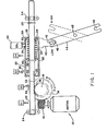
- a small, light-weight, low power reversible motor 10 drives a worm 12 in either sense of rotation.
- the worm drives large gear 14 in a gear set 16 to which is attached a pinion 18.
- gear 14 and pinion 18 are shown for convenience. In actual practice, gear 14 is substantially shown and pinion 18 may be substantially smaller than shown to further increase the torque multiplication substantially provided by the worm 12 and gear 14.
- Sliding bar 20 which has rack teeth 22 slides in bearings schematically as shown at 24. Pinion 18 drives rack 22 as gear 14 is turned out of the forward or reverse direction as shown by the arrow.
- Worm 12 and gear 14 are non-reversing. When motor 10 is stopped, worm 12 locks gear 14, pinion 18, rack 22 and sliding shaft 20 in fixed position.
- Sliding shaft 20 has a lug 26 which moves with the shaft to operate either of microswitches Sl or S2. Rings 28 and 29 are permanently attached to the shaft 20 at predetermined locations.
- Cage 30 surrounds a central portion of the shaft. Ends 32 and 34 of cage 30 have large openings 33 and 35 which permit passage of shaft 20 and rings 28 and 29.
- a lug 36 on cage 30 operates the microswitches S3 and S4. Washers 38 and 39 move within cage 30 and present an abutment for spring 60 and ends 32 and 34. The washers 38 and 39 may be permanently attached to the ends 60 if desired.
- Arm 40 is permanently attached to cage 30 such as by welding. Arm 40 has a permanently attached pin 42 to operate shift lever 44 which pivots on pivot pin 45. Fork 46 of lever 44 receives pin 42 and fork 48 of lever 48 receives a shifting pin on a conventional two-speed axle shift unit which is not shown. Alternatively, arm 40 or a fixed projection on cage 30 may be connected directly to the speed changing gears in the conventional two-speed axle.
- Solenoid 50 operates to quickly release cage 30 so that spring 60 may shift the two-speed axle unit.
- Solenoid 50 has a piston 52 which is pulsed upwardly against return spring force. Piston 52 fits within opening 54 or opening 56 of cage 30. As the piston 52 is pulled upward by solenoid 50, disengaging one hole, the piston moves along the surface of the cage 30 until it is aligned with the other hole, whereupon it is pushed into the hole, retaining the cage in the new position.
- motor 10 has already been cycled in the forward direction F to turn gear 14 and pinion 18 and to move rack 22 to the right to compress spring 60 against end 34 of the cage 30.
- the motor has been shut off by lug 26 engaging microswitch S2.
- a circuit was completed to permit motor 10 to run in the forward direction by virtue of the contact of lug 36 with switch 3.
- solenoid 50 When it is desired to shift from the low speed to the high speed, solenoid 50 is pulsed, pulling piston 52 out of hole 54.
- Spring 60 drives cage 30 to the right to shift arm 44 to the high speed position as shown in dash lines in Figure 1.
Applications Claiming Priority (2)
| Application Number | Priority Date | Filing Date | Title |
|---|---|---|---|
| US06/725,270 US4619151A (en) | 1985-04-19 | 1985-04-19 | Two speed axle shift actuator |
| US725270 | 1985-04-19 |
Publications (3)
| Publication Number | Publication Date |
|---|---|
| EP0198111A2 true EP0198111A2 (fr) | 1986-10-22 |
| EP0198111A3 EP0198111A3 (en) | 1988-10-19 |
| EP0198111B1 EP0198111B1 (fr) | 1990-10-24 |
Family
ID=24913842
Family Applications (1)
| Application Number | Title | Priority Date | Filing Date |
|---|---|---|---|
| EP85111546A Expired - Lifetime EP0198111B1 (fr) | 1985-04-19 | 1985-09-12 | Dispositif de changement de vitesse pour entraînement d'essieux à deux vitesses |
Country Status (7)
| Country | Link |
|---|---|
| US (1) | US4619151A (fr) |
| EP (1) | EP0198111B1 (fr) |
| JP (1) | JPS61244962A (fr) |
| AU (1) | AU586829B2 (fr) |
| BR (1) | BR8504978A (fr) |
| CA (1) | CA1244673A (fr) |
| DE (2) | DE198111T1 (fr) |
Cited By (3)
| Publication number | Priority date | Publication date | Assignee | Title |
|---|---|---|---|---|
| US5507196A (en) * | 1991-11-12 | 1996-04-16 | Zf Friedrichshafen Ag | Gearshifting arrangement for actuating motor vehicle multi-speed gearboxes |
| FR2777834A1 (fr) * | 1998-04-28 | 1999-10-29 | Valeo | Actionneur electromecanique pour boite de vitesse |
| CN104482158A (zh) * | 2014-10-17 | 2015-04-01 | 北京锐光仪器有限公司 | 一种精确旋转机构 |
Families Citing this family (34)
| Publication number | Priority date | Publication date | Assignee | Title |
|---|---|---|---|---|
| DE3309427A1 (de) * | 1982-03-18 | 1983-10-06 | Valeo | Betaetigungsvorrichtung fuer eine kupplung, ein regelgetriebe, eine bremse, oder aehnliches |
| US4745822A (en) * | 1985-04-19 | 1988-05-24 | Rockwell International Corporation | Two speed axle |
| DE3525981A1 (de) * | 1985-07-20 | 1987-01-29 | Schulz Gerd Fahrzeug Cont | Schwenkvorrichtung fuer ein schleuderkettenaggregat eines kraftfahrzeugs |
| US4805472A (en) * | 1986-09-30 | 1989-02-21 | Aisin Seiki Kabushiki Kaisha | Rotary torque transmission apparatus for four-wheel drive vehicles |
| US4821590A (en) * | 1987-06-18 | 1989-04-18 | Tury Edward L | Electronic control system for control of electronic electric shift apparatus for manual transmission |
| US4841793A (en) * | 1987-07-16 | 1989-06-27 | Leigh Monstevens Keith V | Electric shift apparatus |
| GB2207715B (en) * | 1987-07-28 | 1991-10-09 | Gaydon Techn Ltd | Vehicle transmissions |
| US4846010A (en) * | 1987-07-31 | 1989-07-11 | Mazda Motor Corporation | Transfer case operation mode shifting apparatus for a four-wheel drive vehicle |
| DE3876781D1 (de) * | 1987-09-09 | 1993-01-28 | Heinz Frei | Stufenlos regelbarer antrieb. |
| US4843901A (en) * | 1987-09-14 | 1989-07-04 | Peterson David C | Electric shift apparatus with manual override |
| US4793458A (en) * | 1987-11-09 | 1988-12-27 | Dana Corporation | Shift motor assembly for a two-speed axle |
| DE8810248U1 (fr) * | 1988-08-12 | 1988-10-13 | Weiss, Dieter, 6967 Buchen, De | |
| US4873881A (en) * | 1989-01-06 | 1989-10-17 | Eaton Corporation | Electrically actuated x-y shifting mechanism |
| DE3928109A1 (de) * | 1989-08-25 | 1991-02-28 | Bosch Gmbh Robert | Elektromotorisch antreibbarer druckerzeuger fuer eine hydraulische fahrzeug-bremsanlage |
| US5071030A (en) * | 1990-07-26 | 1991-12-10 | Marcusen Carroll L | Adhesive label separator |
| DE4026736A1 (de) * | 1990-08-24 | 1992-02-27 | Montech Ag | Dreheinheit |
| US5180051A (en) * | 1991-06-28 | 1993-01-19 | Square D Company | Remote control circuit breaker |
| US5455609A (en) * | 1992-09-30 | 1995-10-03 | Hewlett-Packard Company | Printhead servicing station for printers |
| JPH07161110A (ja) * | 1993-12-03 | 1995-06-23 | Tanashin Denki Co | 作動装置 |
| JPH10283741A (ja) * | 1997-04-03 | 1998-10-23 | Mitsumi Electric Co Ltd | ウォームギヤを用いたスライド送り機構 |
| US5878624A (en) * | 1997-06-06 | 1999-03-09 | Borg-Warner Automotive, Inc. | Single rail shift operator assembly |
| DE19857714B4 (de) * | 1997-12-23 | 2009-02-19 | Aft Atlas Fahrzeugtechnik Gmbh | Getriebe |
| GB2334067B (en) * | 1998-02-09 | 2002-07-17 | Reilor Ltd | Pet door |
| US6619153B2 (en) * | 2001-03-30 | 2003-09-16 | New Venture Gear, Inc. | Spring-loaded fork assembly for shift system |
| EP1812732A1 (fr) * | 2004-09-02 | 2007-08-01 | Belimo Holding AG | Entrainement lineaire |
| US20090158868A1 (en) * | 2007-11-30 | 2009-06-25 | Stoneridge Control Devices, Inc. | Crank-Type Linear Actuator |
| KR101459322B1 (ko) | 2012-12-27 | 2014-11-07 | 전자부품연구원 | 조작레버의 제한장치 |
| EP2886911B1 (fr) | 2013-12-20 | 2016-08-03 | BorgWarner Inc. | Ensemble actionneur de changement de vitesse sous charge de ressort ayant un mécanisme de retenue |
| CN103807396A (zh) * | 2014-01-23 | 2014-05-21 | 太仓宝达齿条有限公司 | 快速复位齿轮齿条机构 |
| DE102016114492A1 (de) * | 2016-08-04 | 2018-02-08 | Dr. Ing. H.C. F. Porsche Aktiengesellschaft | Drehregler mit mitbewegbarem Kraftspeicher |
| CN106481802B (zh) * | 2016-12-05 | 2018-11-20 | 广州汽车集团股份有限公司 | 换挡执行器 |
| KR102010339B1 (ko) * | 2018-03-14 | 2019-08-13 | (주)세고스 | 액추에이터 |
| EP3825582B1 (fr) * | 2019-11-20 | 2024-04-10 | Stellantis Europe S.p.A. | Système de fonctionnement d'une boîte de vitesses pour un véhicule à moteur |
| DE102019131940A1 (de) * | 2019-11-26 | 2021-05-27 | Knorr-Bremse Systeme für Nutzfahrzeuge GmbH | Aktuatormodul |
Citations (5)
| Publication number | Priority date | Publication date | Assignee | Title |
|---|---|---|---|---|
| FR2322307A1 (fr) * | 1975-09-01 | 1977-03-25 | Peugeot | Ensemble de transmission comportant une boite de vitesses principale en serie avec un relais au moins a deux rapports |
| EP0105588A1 (fr) * | 1982-09-27 | 1984-04-18 | Eaton Corporation | Actionneur pour transmission commandé électriquement |
| US4449416A (en) * | 1981-09-04 | 1984-05-22 | J. I. Case Company | Transmission control system |
| US4485692A (en) * | 1982-06-17 | 1984-12-04 | Moore Jeff D | Auxiliary transmission |
| US4498350A (en) * | 1982-09-20 | 1985-02-12 | Eaton Corporation | Shifting mechanism |
Family Cites Families (22)
| Publication number | Priority date | Publication date | Assignee | Title |
|---|---|---|---|---|
| US1129762A (en) * | 1913-05-08 | 1915-02-23 | Brown & Sharpe Mfg | Reversing mechanism. |
| US1874995A (en) * | 1930-12-26 | 1932-08-30 | Eaton Mfg Co | Rolling machine |
| US2655042A (en) * | 1944-07-03 | 1953-10-13 | Midland Steel Prod Co | Gear shifting mechanism |
| US2695531A (en) * | 1948-06-26 | 1954-11-30 | Bendix Aviat Corp | Electric two-speed axle shifter |
| US2634622A (en) * | 1949-10-07 | 1953-04-14 | Bendix Aviat Corp | Transmission control mechanism |
| US2806689A (en) * | 1955-12-06 | 1957-09-17 | Miller Lee | Electric operator for vertical jalousies |
| US2909940A (en) * | 1956-03-22 | 1959-10-27 | Collins Radio Co | Detent mechanism |
| US3062071A (en) * | 1959-12-29 | 1962-11-06 | Warren P Morrow | Actuator for triggering system |
| US2984065A (en) * | 1960-07-15 | 1961-05-16 | Collins Radio Co | Double acting spring motor |
| US3652815A (en) * | 1971-01-14 | 1972-03-28 | Westinghouse Electric Corp | Circuit interrupter with motor operated spring charging means including two ratchets and two pawls |
| US3773995A (en) * | 1972-10-27 | 1973-11-20 | Westinghouse Electric Corp | Motor advanced spring charging pawl and ratchet mechanism with spring assist |
| US3808895A (en) * | 1973-02-09 | 1974-05-07 | J Fitzwater | Electric fail-safe actuator |
| US3908473A (en) * | 1974-01-09 | 1975-09-30 | Itt | Linear motion snap-action mechanism |
| US3894442A (en) * | 1974-04-15 | 1975-07-15 | Ray Hembree | Semi-automatic electric gear shifting apparatus for a motorcycle |
| US4022077A (en) * | 1974-07-18 | 1977-05-10 | J. I. Case Company | Control means with a spring lever |
| US3998110A (en) * | 1975-09-15 | 1976-12-21 | General Motors Corporation | Transmission shift lever with detent inhibitors |
| US4203573A (en) * | 1976-10-26 | 1980-05-20 | Erie Manufacturing Company | Reversible motor operated valve with spring assist |
| JPS55139551A (en) * | 1979-04-14 | 1980-10-31 | Toyota Motor Corp | Quick motion mechanism |
| US4479357A (en) * | 1980-12-19 | 1984-10-30 | Stewart Glenn D | Method and apparatus for automatically synchronizing multiple engines |
| FR2500043A1 (fr) * | 1981-02-18 | 1982-08-20 | Peugeot Aciers Et Outillage | Dispositif de commande electrique d'un organe d'actionnement |
| US4428248A (en) * | 1981-04-20 | 1984-01-31 | Eaton Corporation | Shifting actuator |
| US4444072A (en) * | 1982-04-30 | 1984-04-24 | General Motors Corporation | Shift mechanism with a neutral stop control for a two-speed transmission |
-
1985
- 1985-04-19 US US06/725,270 patent/US4619151A/en not_active Expired - Fee Related
- 1985-09-06 AU AU47131/85A patent/AU586829B2/en not_active Ceased
- 1985-09-12 DE DE198585111546T patent/DE198111T1/de active Pending
- 1985-09-12 EP EP85111546A patent/EP0198111B1/fr not_active Expired - Lifetime
- 1985-09-12 DE DE8585111546T patent/DE3580268D1/de not_active Expired - Fee Related
- 1985-09-30 CA CA000491894A patent/CA1244673A/fr not_active Expired
- 1985-10-08 BR BR8504978A patent/BR8504978A/pt not_active IP Right Cessation
- 1985-11-06 JP JP60248704A patent/JPS61244962A/ja active Pending
Patent Citations (5)
| Publication number | Priority date | Publication date | Assignee | Title |
|---|---|---|---|---|
| FR2322307A1 (fr) * | 1975-09-01 | 1977-03-25 | Peugeot | Ensemble de transmission comportant une boite de vitesses principale en serie avec un relais au moins a deux rapports |
| US4449416A (en) * | 1981-09-04 | 1984-05-22 | J. I. Case Company | Transmission control system |
| US4485692A (en) * | 1982-06-17 | 1984-12-04 | Moore Jeff D | Auxiliary transmission |
| US4498350A (en) * | 1982-09-20 | 1985-02-12 | Eaton Corporation | Shifting mechanism |
| EP0105588A1 (fr) * | 1982-09-27 | 1984-04-18 | Eaton Corporation | Actionneur pour transmission commandé électriquement |
Cited By (4)
| Publication number | Priority date | Publication date | Assignee | Title |
|---|---|---|---|---|
| US5507196A (en) * | 1991-11-12 | 1996-04-16 | Zf Friedrichshafen Ag | Gearshifting arrangement for actuating motor vehicle multi-speed gearboxes |
| FR2777834A1 (fr) * | 1998-04-28 | 1999-10-29 | Valeo | Actionneur electromecanique pour boite de vitesse |
| WO1999056040A1 (fr) * | 1998-04-28 | 1999-11-04 | Valeo | Actionneur electromecanique pour boite de vitesses mecanique |
| CN104482158A (zh) * | 2014-10-17 | 2015-04-01 | 北京锐光仪器有限公司 | 一种精确旋转机构 |
Also Published As
| Publication number | Publication date |
|---|---|
| EP0198111B1 (fr) | 1990-10-24 |
| US4619151A (en) | 1986-10-28 |
| DE198111T1 (de) | 1987-04-30 |
| JPS61244962A (ja) | 1986-10-31 |
| CA1244673A (fr) | 1988-11-15 |
| BR8504978A (pt) | 1986-12-16 |
| AU586829B2 (en) | 1989-07-27 |
| AU4713185A (en) | 1986-10-23 |
| DE3580268D1 (de) | 1990-11-29 |
| EP0198111A3 (en) | 1988-10-19 |
Similar Documents
| Publication | Publication Date | Title |
|---|---|---|
| US4619151A (en) | Two speed axle shift actuator | |
| US4745822A (en) | Two speed axle | |
| US7712392B2 (en) | Electrical shifting device for a motor vehicle | |
| CA1211640A (fr) | Mecanisme de passage de vitesses | |
| US4997069A (en) | Electromotive drive for a control element | |
| JPH068151A (ja) | 回転電動工具の自動変速装置 | |
| US5408898A (en) | Preselect shift strategy using stored energy | |
| US5970811A (en) | Automatic speed-change apparatus for a gear transmission | |
| CN110637181B (zh) | 具有安全机构的线性致动器 | |
| US5809841A (en) | Variable position detent mechanism for a control lever | |
| CA1119224A (fr) | Mecanisme de commande sur coupe-circuit haute tension | |
| EP1128006B1 (fr) | Ensemble actionneur | |
| JP3391907B2 (ja) | 変速装置 | |
| JP3391906B2 (ja) | 遊星変速装置 | |
| JP3694945B2 (ja) | 変速装置 | |
| JP2020045991A (ja) | 車両用パーキング装置 | |
| JP3758346B2 (ja) | トルククラッチ付締付工具 | |
| JP3314459B2 (ja) | 開閉器の操作装置 | |
| EP3670968B1 (fr) | Dispositif changement de vitesse electronique | |
| WO2022259155A1 (fr) | Ensemble actionneur de découplage rotatif à assistance de ressort intégrée pour mise en prise bloquée | |
| US3256750A (en) | Transfer case shift system | |
| SU1032490A1 (ru) | Трехпозиционный переключатель | |
| SU637291A1 (ru) | Устройство дл переключени ступенчатой коробки передач | |
| JPH06113410A (ja) | 電動装置 | |
| CS268734B1 (en) | Device for speed gear undirect shifting |
Legal Events
| Date | Code | Title | Description |
|---|---|---|---|
| PUAI | Public reference made under article 153(3) epc to a published international application that has entered the european phase |
Free format text: ORIGINAL CODE: 0009012 |
|
| AK | Designated contracting states |
Kind code of ref document: A2 Designated state(s): DE FR GB IT SE |
|
| ITCL | It: translation for ep claims filed |
Representative=s name: SOCIETA' ITALIANA BREVETTI S.P.A. |
|
| EL | Fr: translation of claims filed | ||
| DET | De: translation of patent claims | ||
| PUAL | Search report despatched |
Free format text: ORIGINAL CODE: 0009013 |
|
| AK | Designated contracting states |
Kind code of ref document: A3 Designated state(s): DE FR GB IT SE |
|
| 17P | Request for examination filed |
Effective date: 19890419 |
|
| 17Q | First examination report despatched |
Effective date: 19890821 |
|
| GRAA | (expected) grant |
Free format text: ORIGINAL CODE: 0009210 |
|
| AK | Designated contracting states |
Kind code of ref document: B1 Designated state(s): DE FR GB IT SE |
|
| ET | Fr: translation filed | ||
| REF | Corresponds to: |
Ref document number: 3580268 Country of ref document: DE Date of ref document: 19901129 |
|
| ITF | It: translation for a ep patent filed |
Owner name: SOCIETA' ITALIANA BREVETTI S.P.A. |
|
| PLBE | No opposition filed within time limit |
Free format text: ORIGINAL CODE: 0009261 |
|
| STAA | Information on the status of an ep patent application or granted ep patent |
Free format text: STATUS: NO OPPOSITION FILED WITHIN TIME LIMIT |
|
| 26N | No opposition filed | ||
| ITTA | It: last paid annual fee | ||
| PGFP | Annual fee paid to national office [announced via postgrant information from national office to epo] |
Ref country code: FR Payment date: 19930808 Year of fee payment: 9 |
|
| PGFP | Annual fee paid to national office [announced via postgrant information from national office to epo] |
Ref country code: SE Payment date: 19930813 Year of fee payment: 9 |
|
| PGFP | Annual fee paid to national office [announced via postgrant information from national office to epo] |
Ref country code: DE Payment date: 19930825 Year of fee payment: 9 |
|
| PGFP | Annual fee paid to national office [announced via postgrant information from national office to epo] |
Ref country code: GB Payment date: 19930901 Year of fee payment: 9 |
|
| PG25 | Lapsed in a contracting state [announced via postgrant information from national office to epo] |
Ref country code: GB Effective date: 19940912 |
|
| PG25 | Lapsed in a contracting state [announced via postgrant information from national office to epo] |
Ref country code: SE Effective date: 19940913 |
|
| EAL | Se: european patent in force in sweden |
Ref document number: 85111546.9 |
|
| GBPC | Gb: european patent ceased through non-payment of renewal fee |
Effective date: 19940912 |
|
| PG25 | Lapsed in a contracting state [announced via postgrant information from national office to epo] |
Ref country code: FR Effective date: 19950531 |
|
| PG25 | Lapsed in a contracting state [announced via postgrant information from national office to epo] |
Ref country code: DE Effective date: 19950601 |
|
| EUG | Se: european patent has lapsed |
Ref document number: 85111546.9 |
|
| REG | Reference to a national code |
Ref country code: FR Ref legal event code: ST |