EP0194803A2 - Regulieranordnung für einen Magnetkopf - Google Patents
Regulieranordnung für einen Magnetkopf Download PDFInfo
- Publication number
- EP0194803A2 EP0194803A2 EP86301547A EP86301547A EP0194803A2 EP 0194803 A2 EP0194803 A2 EP 0194803A2 EP 86301547 A EP86301547 A EP 86301547A EP 86301547 A EP86301547 A EP 86301547A EP 0194803 A2 EP0194803 A2 EP 0194803A2
- Authority
- EP
- European Patent Office
- Prior art keywords
- head
- adjustment screw
- magnetic head
- rotating member
- carrier
- Prior art date
- Legal status (The legal status is an assumption and is not a legal conclusion. Google has not performed a legal analysis and makes no representation as to the accuracy of the status listed.)
- Granted
Links
Images


Classifications
-
- G—PHYSICS
- G11—INFORMATION STORAGE
- G11B—INFORMATION STORAGE BASED ON RELATIVE MOVEMENT BETWEEN RECORD CARRIER AND TRANSDUCER
- G11B5/00—Recording by magnetisation or demagnetisation of a record carrier; Reproducing by magnetic means; Record carriers therefor
- G11B5/48—Disposition or mounting of heads or head supports relative to record carriers ; arrangements of heads, e.g. for scanning the record carrier to increase the relative speed
- G11B5/56—Disposition or mounting of heads or head supports relative to record carriers ; arrangements of heads, e.g. for scanning the record carrier to increase the relative speed with provision for moving the head support for the purpose of adjusting the position of the head relative to the record carrier, e.g. manual adjustment for azimuth correction or track centering
Definitions
- the present invention relates to a magnetic recording/reproducing device for magnetically recording and reproducing information by scanning a magnetic head in a radial direction of a circular magnetic disc, and more particularly to a magnetic head adjusting device for adjusting a position and attitude, etc. of the magnetic head relative to the magnetic disc.
- the aforementioned prior art has the following problem.
- the adhesive interposed between the magnetic head and the carrier is changed in size upon curing. Especially, the larger is an amount of the adhesive, the more remarkable is the change in size.
- a position and attitude of the magnetic head bonded to the carrier are changed in association with curing of the adhesive.
- the amount of change in position exceeds a permissible value.
- a head retainer for retaining the magnetic head is mounted to the carrier adapted to reciprocate toward the center of a driving shaft for driving a magnetic disc.
- an azimuth adjusting mechanism is provided for varying the direction of the head retainer with respect to a rotative axis parellel to the driving shaft.
- a head attitude adjusting mechanism is provided for letting the head retainer approach to and move away from the magnetic disc and incline relative to the same plane as the magnetic disc. Owing to the provision of the head attitude adjusting mechanism, a proper spacing between the magnetic head and the magnetic disc may be defined, and simultaneously parallelism of the magnetic head relative to the magnetic disc may be adjusted.
- the head retainer may be displaced in a rotative direction about an axis parallel to the driving shaft to direct a head gap of the magnetic head toward the center of the driving shft. Accordingly, the position and attitude of the magnetic head may be freely adjusted as required in any assembling steps.
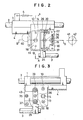
- Two carrier shafts 2 and 3 are arranged in perpendicular relation to a driving shaft 41 for driving a magnetic disc (not shown), and a carrier I is slidably retained to the carrier shafts 2 and 3.
- the carrier 1 is provided with a rack 4 meshing with a driving gear 40, and is biased to one direction by a spring 6 retained to a frame 5 at one end thereof which frame is partially shown.
- there are connected to the carrier 1 a rotating member 11, a head attitude adjustment member 26, a head retainer 22 and a head base 20 having a magnetic head 19 in this order.
- the connections of each member constitute an azimuth adjusting mechanism 18, an off-track adjusting mechanism 34 and a head attitude adjusting mechanism 39.
- a connecting condition of each member and each of the adjusting mechanisms will be explained in the following.
- the head base 20 is fixed to a bent portion 23 formed at the head retainer 22 by a screw 21.
- the head retainer 22 is formed with screw holes 31 with which a rod-like off-track adjustment screw 32 is threadedly engaged.
- the off-track adjustment screw 32 is rotatably supported to projections 33 formed at the head attitude adjustment member 26 with axial movement of the screw inhibited.
- the off-track adjustment screw 32 is arranged in such a direction that its axial direction is perpendicular to both axial directions of the carrier shafts 2 and 3 and the driving shaft 41. Both of the head retainer 22 and the head attitude adjustment member 26 are fixable by head retainer fastening screws 29.
- the head retainer fastening screws 29 are inserted through washers 27 and spring washers 28 into elongated holes 25 formed at the head attitude adjustment member 26, and are threadedly engaged with screw holes 30 formed at the head retainer 22.
- the aforementioned off-track adjusting mechanism is constituted.
- the rotating member 11 is formed with three holes 17 at predetermined positions, and the head attitude adjustment member 26 is formed with screw holes 24 at such positions as to mate with these holes 17.
- First, second and third adjustment screws 35, 36 and 37 are inserted through the holes 17 from the back side of the carrier 1, and are threadedly engaged through elastic members 38 with the screw holes 24.
- the screw hole 24 engaged with the first adjustment screw 35 is opposed to the center of the magnetic head 19.
- the screw hole 24 engaged with the second adjustment screw 36 is positioned on a line connecting the center 42 of the driving shaft 41 with the first adjustment screw 35.
- the screw hole 24 engaged with the third adjustment screw 37 is positioned on a line perpendicular to a line connecting the first adjustment screw 35 with the second adjustment screw 36, which former line passing through the first adjustment screw 35.
- Head portions of the adjustment screws 35, 36 and 37 are positioned in a space part of the carrier 1, and has no engagement relation with the carrier 1.
- the elastic members 38 are formed by spirally winding a steel wire once.
- the aforementioned head attitude adjusting mechanism 39 is constituted.
- the rotating member 11 is rotatable about the first adjustment screw 37 relative to the carrier 1. Further, the carrier 1 and the rotating member 11 are fixable to each other by means of rotating member fastening screws 10. That is to say, the rotating member fastening screws 10 are inserted through washers 8 and spring washers 9 into two holes 7 formed at the carrier 1, and are threadedly engaged with screw holes 12 formed at the rotating member 11.
- the carrier 1 is formed with a circular hole 13.
- a base portion of an eccentric cam 15 is inserted into the hole 13 from the back side of the carrier 1 and is rotatably retained in the hole 13.
- the eccentric cam 15 is provided with a projection 16 formed eccentrically from the axis at the free end thereof. The projection 16 is engaged with an elongated engagement hole 14 formed at the rotating member 11.
- the aforementioned azimuth adjusting mechanism 18 is constituted.
- An adjustment operation of the magnetic head 19 is carried out in the following manner.
- the adjustment screws 35, 36 and 37 are rotated to let the head attitude adjustment member 26 approach to or move away from one surface of the magnetic disc, thereby determining a facing position of the magnetic head 19 relative to the magnetic disc.
- fastening extent of the three adjustment screws 35, 36 and 37 is adjusted to adjust parallelism of the head attitude adjustment member 26 relative to the one surface of the magnetic disc and thereby obtain a parallel contact condition of the magnetic head 19 to the magnetic disc.
- the off-track adjustment screw 32 is rotated to displace the head retainer 22 relative to the head attitude adjustment member 26.
- the magnetic head 19 is displaced in such a direction as perpendicular to both the moving direction of the carrier 1 and the axial direction of the driving shaft 41, and is positioned on a line parallel to the moving direction of the carrier 1 and passing through the center 42 of the driving shaft 41.
- the head retainer 22 is displaced in tight contact with the head attitude adjustment member 26 the parallelism of which has been adjusted, the contact condition of the magnetic head 19 to the magnetic disc is not varied.
- Such adjustment of off-track may be carried out with the head retainer fastening screws 29 remaining fastened because a range of the adjustment is in a micron unit.
- the eccentric cam 15 engaged with the circular hole 13 of the carrier 1 is rotated to rotate the rotating member 11 by means of the projection 16 and direct the head gap of the magnetic head 19 toward the center 42 of the driving shaft 41.
- an azimuth angle of the magnetic head 19 is adjusted.
- the adjustment may be carried out with the rotating member fastening screws 10 remaining fastened.
- each of the aforementioned adjusting operations may be carried out at an arbitral time during or after assembling.
- the magnetic head 19 may be displaced to various positions and directions by combining each of the adjusting operations to expectedly attain accurate adjustment. Accordingly, even -if it is found that the position of the magnetic head 19 is incorrect after assembling of the device, the magnetic head 19 may be easily corrected to the accurate position, and as a result, defective assembling may be recovered.
- a first adjustment screw 44 having a head portion 45 adapted to urge the back surface of the carrier I may be used in substitution for the first adjustment screw 35 to cramp both the carrier 1 and the rotating member 11 by means of the head portion 45 and the elastic member 38.
- the elastic member 38 may include a coil spring and rubber, etc.
Landscapes
- Adjustment Of The Magnetic Head Position Track Following On Tapes (AREA)
- Supporting Of Heads In Record-Carrier Devices (AREA)
Applications Claiming Priority (2)
| Application Number | Priority Date | Filing Date | Title |
|---|---|---|---|
| JP60053088A JPS61210513A (ja) | 1985-03-15 | 1985-03-15 | 磁気ヘツド調整装置 |
| JP53088/85 | 1985-03-15 |
Publications (3)
| Publication Number | Publication Date |
|---|---|
| EP0194803A2 true EP0194803A2 (de) | 1986-09-17 |
| EP0194803A3 EP0194803A3 (en) | 1987-09-16 |
| EP0194803B1 EP0194803B1 (de) | 1991-11-13 |
Family
ID=12933025
Family Applications (1)
| Application Number | Title | Priority Date | Filing Date |
|---|---|---|---|
| EP86301547A Expired EP0194803B1 (de) | 1985-03-15 | 1986-03-05 | Regulieranordnung für einen Magnetkopf |
Country Status (4)
| Country | Link |
|---|---|
| US (1) | US4774614A (de) |
| EP (1) | EP0194803B1 (de) |
| JP (1) | JPS61210513A (de) |
| DE (1) | DE3682414D1 (de) |
Families Citing this family (5)
| Publication number | Priority date | Publication date | Assignee | Title |
|---|---|---|---|---|
| JP2572390B2 (ja) * | 1987-05-28 | 1997-01-16 | キヤノン電子株式会社 | デイスク装置 |
| JPS6437785A (en) * | 1987-07-31 | 1989-02-08 | Matsushita Electric Ind Co Ltd | Recording and reproducing device |
| JP2606428B2 (ja) * | 1990-09-21 | 1997-05-07 | ティアツク株式会社 | ディスク装置のヘッドキャリッジ |
| JPH05159483A (ja) * | 1991-06-10 | 1993-06-25 | Seiko Epson Corp | ディスク装置 |
| KR0119723Y1 (ko) * | 1995-03-29 | 1998-08-01 | 배순훈 | 테이프 레코더의 오디오/콘트롤헤드 조립구조 |
Citations (1)
| Publication number | Priority date | Publication date | Assignee | Title |
|---|---|---|---|---|
| JPS6083215A (ja) * | 1983-10-13 | 1985-05-11 | Fuji Photo Film Co Ltd | 磁気ヘツドの調整装置 |
Family Cites Families (5)
| Publication number | Priority date | Publication date | Assignee | Title |
|---|---|---|---|---|
| US4097908A (en) * | 1976-09-17 | 1978-06-27 | Shugart Associates | Method for inspecting the skew of a magnetic head, for selectively locating a lead screw and an apparatus therefor |
| US4133015A (en) * | 1977-03-16 | 1979-01-02 | Sycor, Inc. | Head positioner for disc recorders |
| JPS6025067A (ja) * | 1983-07-20 | 1985-02-07 | Canon Inc | 記録再生装置におけるヘツドキヤリアの軸振れ防止機構 |
| US4587587A (en) * | 1983-07-29 | 1986-05-06 | Eastman Kodak Company | Dual transducer assembly with linear adjustment |
| JPS60163223A (ja) * | 1984-02-01 | 1985-08-26 | Fuji Photo Film Co Ltd | 磁気ヘツドの調整装置 |
-
1985
- 1985-03-15 JP JP60053088A patent/JPS61210513A/ja active Pending
-
1986
- 1986-03-04 US US06/836,149 patent/US4774614A/en not_active Expired - Fee Related
- 1986-03-05 DE DE8686301547T patent/DE3682414D1/de not_active Expired - Lifetime
- 1986-03-05 EP EP86301547A patent/EP0194803B1/de not_active Expired
Patent Citations (1)
| Publication number | Priority date | Publication date | Assignee | Title |
|---|---|---|---|---|
| JPS6083215A (ja) * | 1983-10-13 | 1985-05-11 | Fuji Photo Film Co Ltd | 磁気ヘツドの調整装置 |
Non-Patent Citations (2)
| Title |
|---|
| IBM TECHNICAL DISCLOSURE BULLETIN, vol. 10, no. 12, May 1968, pages 1906-1907, Armonk, New York, US; A.B. HABICH: "Adjustable magnetic head" * |
| PATENT ABSTRACTS OF JAPAN, vol. 9, no. 227 (P-388)[1950], 13th September 1985; & JP-A-60 83 215 (FUJI SHASHIN FILM K.K.) 11-05-1985 * |
Also Published As
| Publication number | Publication date |
|---|---|
| DE3682414D1 (de) | 1991-12-19 |
| US4774614A (en) | 1988-09-27 |
| EP0194803B1 (de) | 1991-11-13 |
| EP0194803A3 (en) | 1987-09-16 |
| JPS61210513A (ja) | 1986-09-18 |
Similar Documents
| Publication | Publication Date | Title |
|---|---|---|
| US6567362B1 (en) | Optical disk device having guide shaft for guiding optical pickup | |
| US5331490A (en) | Tape head fine positioning system for a tape backup drive | |
| US5889755A (en) | Pickup adjusting apparatus of an optical disk player | |
| US4875120A (en) | Head driving apparatus with coarse and fine adjustments | |
| EP0194803A2 (de) | Regulieranordnung für einen Magnetkopf | |
| US5309628A (en) | Assembling position adjusting mechanism of a spindle motor for a magnetic disk apparatus | |
| US7133262B1 (en) | Tape drive apparatus with a head alignment system | |
| US4809106A (en) | Lead screw/transducer aligning mechanism for disk drive apparatus | |
| EP0469191B1 (de) | Zahnradgetriebe und Schrittmotor-Einstellungssysteme | |
| US5146377A (en) | Adjustable magnetic head mounting system | |
| JPH0728622Y2 (ja) | ヘッドキャリッジ駆動用ステッピングモータ | |
| US5479307A (en) | Audio head position adjusting device for a video cassette recorder | |
| US5307703A (en) | Head adjusting device | |
| JPH10188498A (ja) | 光学ピックアップ送り用ラック | |
| JP2517896B2 (ja) | ヘッド送り装置 | |
| JPH10143870A (ja) | 光ディスクシステムの光軸調整機構 | |
| JP3214171B2 (ja) | ディスクプレーヤ | |
| KR910003399Y1 (ko) | 테이프레코오더의 자기헤드장치 | |
| JPH0693313B2 (ja) | キヤリツジ駆動機構 | |
| JPH03268278A (ja) | ピックアップ案内装置 | |
| US6795276B2 (en) | Flexible disk drive having a support plate coupled to a pedestal on the main plate by a plurality of projections and a screw | |
| JP2918467B2 (ja) | Vtr用コントロールヘッドの位置決め装置 | |
| KR940002976Y1 (ko) | 고밀도용 플로피 디스크 드라이브의 방위각 조절장치 | |
| JPH0535481Y2 (de) | ||
| JPS61289581A (ja) | 磁気ヘツド送り機構 |
Legal Events
| Date | Code | Title | Description |
|---|---|---|---|
| PUAI | Public reference made under article 153(3) epc to a published international application that has entered the european phase |
Free format text: ORIGINAL CODE: 0009012 |
|
| AK | Designated contracting states |
Kind code of ref document: A2 Designated state(s): DE FR GB |
|
| PUAL | Search report despatched |
Free format text: ORIGINAL CODE: 0009013 |
|
| AK | Designated contracting states |
Kind code of ref document: A3 Designated state(s): DE FR GB |
|
| 17P | Request for examination filed |
Effective date: 19880217 |
|
| 17Q | First examination report despatched |
Effective date: 19891024 |
|
| GRAA | (expected) grant |
Free format text: ORIGINAL CODE: 0009210 |
|
| AK | Designated contracting states |
Kind code of ref document: B1 Designated state(s): DE FR GB |
|
| REF | Corresponds to: |
Ref document number: 3682414 Country of ref document: DE Date of ref document: 19911219 |
|
| ET | Fr: translation filed | ||
| PGFP | Annual fee paid to national office [announced via postgrant information from national office to epo] |
Ref country code: GB Payment date: 19920224 Year of fee payment: 7 |
|
| PLBE | No opposition filed within time limit |
Free format text: ORIGINAL CODE: 0009261 |
|
| STAA | Information on the status of an ep patent application or granted ep patent |
Free format text: STATUS: NO OPPOSITION FILED WITHIN TIME LIMIT |
|
| 26N | No opposition filed | ||
| PG25 | Lapsed in a contracting state [announced via postgrant information from national office to epo] |
Ref country code: FR Effective date: 19921130 |
|
| PG25 | Lapsed in a contracting state [announced via postgrant information from national office to epo] |
Ref country code: DE Effective date: 19921201 |
|
| REG | Reference to a national code |
Ref country code: FR Ref legal event code: ST |
|
| PG25 | Lapsed in a contracting state [announced via postgrant information from national office to epo] |
Ref country code: GB Effective date: 19930305 |
|
| GBPC | Gb: european patent ceased through non-payment of renewal fee |
Effective date: 19930305 |