EP0193384A2 - Ensemble et appareil pour l'alimentation d'articles - Google Patents
Ensemble et appareil pour l'alimentation d'articles Download PDFInfo
- Publication number
- EP0193384A2 EP0193384A2 EP86301350A EP86301350A EP0193384A2 EP 0193384 A2 EP0193384 A2 EP 0193384A2 EP 86301350 A EP86301350 A EP 86301350A EP 86301350 A EP86301350 A EP 86301350A EP 0193384 A2 EP0193384 A2 EP 0193384A2
- Authority
- EP
- European Patent Office
- Prior art keywords
- tube
- articles
- slide
- tubes
- package
- Prior art date
- Legal status (The legal status is an assumption and is not a legal conclusion. Google has not performed a legal analysis and makes no representation as to the accuracy of the status listed.)
- Granted
Links
- 238000013459 approach Methods 0.000 claims description 3
- 239000000853 adhesive Substances 0.000 claims description 2
- 230000001070 adhesive effect Effects 0.000 claims description 2
- 241000282887 Suidae Species 0.000 description 1
- 238000010276 construction Methods 0.000 description 1
- 230000000694 effects Effects 0.000 description 1
- 239000004744 fabric Substances 0.000 description 1
- 230000005484 gravity Effects 0.000 description 1
- 239000012943 hotmelt Substances 0.000 description 1
- 238000009434 installation Methods 0.000 description 1
- 230000013011 mating Effects 0.000 description 1
Images


Classifications
-
- H—ELECTRICITY
- H05—ELECTRIC TECHNIQUES NOT OTHERWISE PROVIDED FOR
- H05K—PRINTED CIRCUITS; CASINGS OR CONSTRUCTIONAL DETAILS OF ELECTRIC APPARATUS; MANUFACTURE OF ASSEMBLAGES OF ELECTRICAL COMPONENTS
- H05K13/00—Apparatus or processes specially adapted for manufacturing or adjusting assemblages of electric components
- H05K13/0084—Containers and magazines for components, e.g. tube-like magazines
-
- Y—GENERAL TAGGING OF NEW TECHNOLOGICAL DEVELOPMENTS; GENERAL TAGGING OF CROSS-SECTIONAL TECHNOLOGIES SPANNING OVER SEVERAL SECTIONS OF THE IPC; TECHNICAL SUBJECTS COVERED BY FORMER USPC CROSS-REFERENCE ART COLLECTIONS [XRACs] AND DIGESTS
- Y10—TECHNICAL SUBJECTS COVERED BY FORMER USPC
- Y10T—TECHNICAL SUBJECTS COVERED BY FORMER US CLASSIFICATION
- Y10T29/00—Metal working
- Y10T29/53—Means to assemble or disassemble
- Y10T29/5313—Means to assemble electrical device
- Y10T29/53174—Means to fasten electrical component to wiring board, base, or substrate
- Y10T29/53183—Multilead component
Definitions
- This invention relates generally to the automatic dispensing of articles, and in particular to the installation of electrical components such as connectors on printed circuit boards and, more particularly, to delivery of connectors to a location where they can be picked up by a robot and installed on a printed circuit board.
- the invention provides an apparatus for dispensing articles from tubes secured to and arranged in spaced parallelism across a tape, each tube having a closure at each end for holding articles therein, said apparatus comprising a stand provided with upper and lower tube support members, a slide for receiving articles from a tube, said slide extending downwardly from the lower support member to a pick-up position, a stepping device for advancing successive tubes over said support members to said slide, and means on the lower support member for opening the closure at the lower end of each tube in its approach to the slide.
- the invention provides a package for dispensible articles, said package comprising at least one elongate tape and a plurality of spaced, article-containing tubes secured to and extending across said tape.
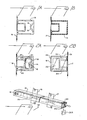
- FIG. 4 An apparatus 10 for dispensing connectors is shown in Fig. 4 and a package 12 adapted for use with the apparatus 10 is shown in Figs. 1-3.
- the package 12 is an elongated belt having plural parallel plastic tubes 14 arranged transversely of a pair of tapes 16,17. Tapes 16,17 are strips or webs of an industrial fabric. Tubes 14 are equispaced and secured to the tapes with a hot melt plastic adhesive.
- Empty tubes 14 are shown in Figs. 1, 1A and 1B. They are U-shaped in cross section and, at one end, have closures in the form of tabs 18 struck and bent inwardly from the outer wall of each tube. As shown in Figs. 2, 2A and 2B, the U-shaped configuration adapts the tubes to carry plural articles such as connectors 20 having dual-in- line rows of contacts 22. A typical example is a horizontal card connector which is adapted to receive another connector having mating pins. After each tube is filled with connectors, its other end is closed with a piece 24 of paper tape.
- each elongated belt 12 is shipped in a cardboard carton 26 which, when opened, is placed on a shelf 28.
- Shelf 28 is pivotally mounted at 30 to a stand 32.
- Above shelf 28 there is a platform 34 which is pivotally mounted on stand 32 at 36. Shelf 28 and platform 34 are pivoted with respect to stand 32 by a handwheel 38 and a tie-rod 40. Movement of carton 26 on the tilted shelf 28 is prevented by a flange 42.
- An end of belt 1 2 is trained over a spaced pair of sprocket wheels 43,44 which are fixed on a shaft 45.
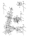
- Shaft 45 is mounted in bearings on upper and lower support members 46,48 and is coupled to a stepping motor 50 provided with a control box 51- Motor 50 and the sprocket wheels 43,44 will be referred to herein as a stepping device.
- support members 46,48 are recessed on their inner sides to provide arcuate guide surfaces 47,49 for the ends of tubes 14.
- a slug of the paper tape 24 is removed by a cutting device 52.
- a slot 54 (Fig. 6) through which connectors 20 pass to a slide 56. Presence of the first connector 20 on a pick-up position defined by a stop plate 58 is detected by a first sensor 60.
- the second and third connectors 20 are held in place by the actuating rods of air cylinders 63,64 until the first connector has been picked up by a robot Cylinder 63 has a fixed mount 65 and cylinder 64 has a movable mount 66. Cylinders 63,6 4 will be referred to herein as an escapement
- Figs. 4, 5 and 7 Movability of the mount 66 is shown in Figs. 4, 5 and 7 where it is seen that cylinder 6 4 is threaded into an aperture through a lateral extension from a T-shaped plate 67.
- the end of the rod in cylinder 64 carries a cap 64c .
- Plate 67 is attached to a dovetail or tenon 68 and the tenon is clamped in a mortise 69 by a set screw 70.
- a vibrator 72 mounted on the bottom of slide 56. Vibrator 72 is attached to a fin 73 which depends from an elongated, T-shaped element 74. Fin 73 projects through a slot 75 in the body of slide 56. A second slot 75 is shown in Figs. 5 and 8. As shown in Fig. 7, the base of the T-shaped element 74 fits in channels at the bottom of a groove 76. A narrowed end of T-shaped element 74 extends through slot 54 (Fig. 6) and contacts the tube 14 then in the dispensing position. Movement of connectors from that tube and along the top of element 74 is assisted by the force of gravity and by the jiggling motion imparted by vibrator 72. Vibrator 72, cutting device 52 and the photodetectors are wired through a junction box 71 (Fig. 4).
- sensors 60,61,62 have two elements. One element is a light source, the other a photodetector. These elements have been designated 60s, 60p, 61 and 62g.
- Figs. 9 and 10 Specific features of the cutting device 52 have been illustrated in Figs. 9 and 10. There are two blades 77 on a plunger 78 which is slidable in a housing 80 and is provided with an actuator, indicated by an arrow 81, for moving the blades through a paper tape 24.
- Fig. 10 shows how a cut slug 24s is removed by the application of a vacuum to a tube 82.
- the vibrator 72 remains active until another connector reaches the extended rod of cylinder 63.
- the connector on the pick-up position at the stop plate is then ready to be picked up by a robot which installs it on a circuit board or other component. Removal of the bottom connector on slide 56 is sensed by detector 60 and the cylinders 63,64 are again sequenced to release another connector. As noted above, movement of the connectors, when released, is assisted by the jiggling motion imparted by vibrator 72.
- the sensed signal activates the stepping motor 50 and another tube is indexed to the top position, with its opened end in line with slot 5 4 in support member 48.
- the presence of a connector is sensed by photodetector 62.
- the sensed signal activates an alarm and inactivates the apparatus.
- a slug 24 s is cut from paper 24 to open the tube but the connectors 20 cannot escape until the tube is indexed to the location of slot 54.
- the spent length of belt 12 falls into another carton placed between the carton 26.
- connectors are dispensed to a pick-up position where they can be picked up by a robot and installed in successive circuit boards as the boards are advanced through a fully automated system.
- a programmed controller is used to receive the sensed signals and to initiate the activities mentioned herein.
- the ends of the tubes to be opened can be closed by polymeric pins of the type shown at 84 in Figs. 11 and 12.
- the ends to be opened are closed by tabs 18', as shown in Figs.14-18.
- a preferred modified dispensing apparatus according to the invention is shown in Figs. 13, 19, 20 and has been designated by the numeral 10'. Details of the tube-opening device are shown in and will be described in connection with Figs. 14-18.
- Vibrator 72' is a VIBROLA-TORn ball type vibrator, Model No. CV-10 (Martin Engineering Co., Neponset, IL).
- An end section 8 5 of slide 56' is pivotally mounted at 86 between a pair of plates 87 and the plates 87 are fixedly attached to the sides of slide 56'. End section 85 is moved between a position of alignment with slide 56' and a horizontal position by a piston-cylinder assembly 88.
- the pivoted end section 85 has a U-shaped groove 89 defined by a central rail 90 which receives connectors 20 from slide 56'.
- vibrator 72' is fastened to a T-shaped slide element 7 4 ' and that this assembly is normally biased by a spring 91 to a position where the upper end of slide 74' engages a tube 14'.
- the upper end of slide 74' is moved away from the path of the tubes over the guiding surface on support member 4 8' by an air cylinder 92 for the purpose of avoiding a jam between slide 74' and the next tube 1 4'.
- end section 85 When the presence of a connector 20' is sensed by detector 60', end section 85 is moved to its horizontal position to facilitate pick-up by a robot. As soon as the connector at the end of section 85 has been picked up and before release of the next connector by the air cylinder 63', section 85 is returned to its position of alignment with slide 56'.
- each tube 1 4 ' to be opened by device 52' is closed by tabs 18' struck and bent inwardly from the outer wall.
- Device 52' has a plunger 78' which is slidable in a housing 80' and is provided with an actuator, indicated by an arrow 81', for moving the plunger into the end of tube 14'.
- Plunger 78' has a tip 92 which is T-shaped in cross section (Fig. 14).
- Tip 92 has a base which is rounded across its bottom and a tapered leg 93 which is rounded at its top.
- Leg 93 has its leading and trailing edges disposed at angles of about 45°. The base fits easily into a tube 14' where its leading edge engages the outer wall (Fig. 16) of the tube and the tabs 18' (Fig. 17) which are bent outwardly from the wall of the tube.
- tabs 1 8' are held in an interference fit (Fig. 18) and tube 14' is open for the discharge of connectors 20' when it reaches the slot at the top of lower support member 48' - (Fig. 13). Because of the angularly disposed leading and trailing edges and the rounded top of leg 93, the upper wall of the tube is deformed but does not tear as tip 78' is inserted and withdrawn.
Landscapes
- Engineering & Computer Science (AREA)
- Manufacturing & Machinery (AREA)
- Microelectronics & Electronic Packaging (AREA)
- Specific Conveyance Elements (AREA)
- Manufacturing Of Electrical Connectors (AREA)
- Container Filling Or Packaging Operations (AREA)
- Automatic Assembly (AREA)
- Branching, Merging, And Special Transfer Between Conveyors (AREA)
Applications Claiming Priority (4)
| Application Number | Priority Date | Filing Date | Title |
|---|---|---|---|
| US70518185A | 1985-02-25 | 1985-02-25 | |
| US06/799,525 US4690302A (en) | 1985-02-25 | 1985-11-22 | Package and apparatus for dispensing electrical connectors |
| US799525 | 1985-11-22 | ||
| US705181 | 2000-11-02 |
Publications (3)
| Publication Number | Publication Date |
|---|---|
| EP0193384A2 true EP0193384A2 (fr) | 1986-09-03 |
| EP0193384A3 EP0193384A3 (en) | 1988-06-01 |
| EP0193384B1 EP0193384B1 (fr) | 1992-05-20 |
Family
ID=27107453
Family Applications (1)
| Application Number | Title | Priority Date | Filing Date |
|---|---|---|---|
| EP86301350A Expired - Lifetime EP0193384B1 (fr) | 1985-02-25 | 1986-02-25 | Ensemble et appareil pour l'alimentation d'articles |
Country Status (5)
| Country | Link |
|---|---|
| US (1) | US4690302A (fr) |
| EP (1) | EP0193384B1 (fr) |
| JP (2) | JPH0734384B2 (fr) |
| CA (1) | CA1259287A (fr) |
| DE (1) | DE3685345D1 (fr) |
Cited By (3)
| Publication number | Priority date | Publication date | Assignee | Title |
|---|---|---|---|---|
| EP0300059A4 (fr) * | 1987-02-06 | 1990-04-10 | Takasago Electric Industry Co | Appareil de traitement des composants electroniques. |
| EP0346903A3 (fr) * | 1988-06-16 | 1990-12-27 | Multitest Elektronische Systeme GmbH | Dispositif d'isolation d'objets du même type, en particulier de composants électroniques, comme les circuits intégrés |
| WO1993005637A1 (fr) * | 1991-08-29 | 1993-03-18 | Vlsi Technology, Inc. | Chargeur de magasin de circuit par transfert automatique sur bande utilisant un point de pivotement |
Families Citing this family (10)
| Publication number | Priority date | Publication date | Assignee | Title |
|---|---|---|---|---|
| US4850785A (en) * | 1987-03-13 | 1989-07-25 | Quality Automation, Inc. | Eprom feed apparatus |
| US4952109A (en) * | 1988-02-19 | 1990-08-28 | Excellon Automation | Modular feeding tray for vibrating conveyors |
| US4941795A (en) * | 1988-11-21 | 1990-07-17 | At&T Bell Laboratories | Component insertion machine apparatus |
| US5215213A (en) * | 1989-06-22 | 1993-06-01 | Richard F. Nestler & Associates, Inc. | Item storage and dispensing apparatus |
| US5217120A (en) * | 1989-08-31 | 1993-06-08 | Goldstar Co., Ltd. | Apparatus for loading and unloading sleeves for integrated circuit ester |
| US5116185A (en) * | 1990-05-01 | 1992-05-26 | Lsi Logic Corp. | Vibratory tube-to-tube transfer system |
| JP2969910B2 (ja) * | 1990-10-29 | 1999-11-02 | 松下電器産業株式会社 | 部品実装方法 |
| US5154316A (en) * | 1990-11-14 | 1992-10-13 | Gregory W. Holcomb | Horizontal oscillatory feeder |
| US5165837A (en) * | 1991-02-06 | 1992-11-24 | Amp Incorporated | Apparatus for feeding articles from tube magazines |
| US5110255A (en) * | 1991-07-19 | 1992-05-05 | Panduit Corp. | Connector feeding apparatus for a connector termination press |
Family Cites Families (21)
| Publication number | Priority date | Publication date | Assignee | Title |
|---|---|---|---|---|
| US3127177A (en) * | 1964-03-31 | Golf ball dispensing and teeing device | ||
| US1683950A (en) * | 1926-10-22 | 1928-09-11 | Fred L Borchert | Cup dispenser |
| US2583700A (en) * | 1948-02-16 | 1952-01-29 | Bernardin Bottle Cap Co Inc | Device for feeding closure caps to containers |
| US3253735A (en) * | 1965-02-08 | 1966-05-31 | Western Electric Co | Apparatus for orienting articles |
| US3374924A (en) * | 1966-08-23 | 1968-03-26 | Western Electric Co | Apparatus for jogging and dispensing articles from a rack |
| US3727757A (en) * | 1972-06-12 | 1973-04-17 | C Boissicat | Dip handling apparatus |
| US3938649A (en) * | 1974-11-29 | 1976-02-17 | F. Jos. Lamb Company | Workpiece elevator |
| JPS58498B2 (ja) * | 1975-12-12 | 1983-01-06 | 新日本製鐵株式会社 | シヨウケツゲンリヨウノソウニユウホウホウ |
| US4169541A (en) * | 1977-12-15 | 1979-10-02 | Universal Instruments Corporation | DIP component storage and dispensing magazine |
| DE2844169C2 (de) * | 1978-10-10 | 1984-10-25 | Gerd Dipl.-Ing. 8011 Faistenhaar Stückler | Vorrichtung zum Bestücken gedruckter Schaltungen |
| US4212102A (en) * | 1978-11-22 | 1980-07-15 | Burroughs Corporation | IC Socket insertion tool |
| US4288023A (en) * | 1979-07-12 | 1981-09-08 | Orthodyne Electronics | Parts storage and handling system |
| DE3003210A1 (de) * | 1980-01-30 | 1981-08-06 | Opti Patent-, Forschungs- und Fabrikations-AG, 8750 Glarus | Anordnung fuer die manipulation von verpackten reissverschluessen |
| US4354615A (en) * | 1980-11-06 | 1982-10-19 | Cavalier Corporation | Alternator mechanism for dispensing machine |
| JPS57127628A (en) * | 1981-01-27 | 1982-08-07 | Citizen Watch Co Ltd | Parts feeding device |
| US4401234A (en) * | 1981-06-01 | 1983-08-30 | Universal Research Laboratories, Incorporated | Apparatus for applying integrated circuits to a circuit board |
| GB2121764B (en) * | 1982-05-27 | 1986-02-05 | Astralux Dynamics Ltd | Component packing tubes |
| JPS58191699U (ja) * | 1982-06-16 | 1983-12-20 | 三菱電機株式会社 | 電子部品用マガジンの保持治具 |
| US4500246A (en) * | 1983-03-01 | 1985-02-19 | Universal Instruments Corporation | Indexed feed of electronic component supply tubes |
| DE3502247A1 (de) * | 1985-01-24 | 1986-07-24 | Technoform Caprano + Brunnhofer KG, 3501 Fuldabrück | Anordnung zum transport und fuer die bereithaltung von elektronischen bauelementen sowie von bauelementen fuer elekronische apparate |
| US4599026A (en) * | 1985-02-26 | 1986-07-08 | Amp Incorporated | Apparatus for providing a continuous supply of workpieces |
-
1985
- 1985-11-22 US US06/799,525 patent/US4690302A/en not_active Expired - Lifetime
-
1986
- 1986-02-20 CA CA000502291A patent/CA1259287A/fr not_active Expired
- 1986-02-24 JP JP61037554A patent/JPH0734384B2/ja not_active Expired - Lifetime
- 1986-02-25 DE DE8686301350T patent/DE3685345D1/de not_active Expired - Lifetime
- 1986-02-25 EP EP86301350A patent/EP0193384B1/fr not_active Expired - Lifetime
-
1994
- 1994-06-15 JP JP6133125A patent/JPH0773952A/ja active Pending
Cited By (3)
| Publication number | Priority date | Publication date | Assignee | Title |
|---|---|---|---|---|
| EP0300059A4 (fr) * | 1987-02-06 | 1990-04-10 | Takasago Electric Industry Co | Appareil de traitement des composants electroniques. |
| EP0346903A3 (fr) * | 1988-06-16 | 1990-12-27 | Multitest Elektronische Systeme GmbH | Dispositif d'isolation d'objets du même type, en particulier de composants électroniques, comme les circuits intégrés |
| WO1993005637A1 (fr) * | 1991-08-29 | 1993-03-18 | Vlsi Technology, Inc. | Chargeur de magasin de circuit par transfert automatique sur bande utilisant un point de pivotement |
Also Published As
| Publication number | Publication date |
|---|---|
| US4690302A (en) | 1987-09-01 |
| EP0193384B1 (fr) | 1992-05-20 |
| CA1259287A (fr) | 1989-09-12 |
| JPH0773952A (ja) | 1995-03-17 |
| EP0193384A3 (en) | 1988-06-01 |
| DE3685345D1 (de) | 1992-06-25 |
| JPH0734384B2 (ja) | 1995-04-12 |
| JPS61195574A (ja) | 1986-08-29 |
Similar Documents
| Publication | Publication Date | Title |
|---|---|---|
| EP0193384B1 (fr) | Ensemble et appareil pour l'alimentation d'articles | |
| CA1127774A (fr) | Dispositif de montage de composants electroniques | |
| US5569353A (en) | Labelling machine and apparatus for the automatic loading of the main magazine of a labelling machine, and a supply magazine which can be used in such an apparatus | |
| EP2793030B1 (fr) | Organe de préhension de tube de test, unité d'étiquetage de tubes d'essai et appareil de préparation de tubes d'essai la comprenant | |
| US10271469B2 (en) | Component supply device and component installation device | |
| US20100042254A1 (en) | Method of feeding flattened cardboard cartons in a carton opening machine in a bottle, container, or article packaging plant, and a device therefor | |
| US5871696A (en) | Cassette for blood smear slides and cooperative slide ejection assembly | |
| US4763780A (en) | Package and apparatus for dispensing electrical connectors | |
| CN111542477B (zh) | 用于将标签施加到香烟包装件上的方法和设备 | |
| EP1695932B1 (fr) | Sytèmes et procédés pour dispenser des objects | |
| US4761106A (en) | Part feeder | |
| US5733093A (en) | Stack tube feeder | |
| KR960005539B1 (ko) | 부품 공급 장치 | |
| KR101975597B1 (ko) | 라벨부착기용 릴 이송장치 | |
| JPH10209672A (ja) | 部品のテーピング方法と装置 | |
| EP1884367B1 (fr) | Dispositif de chargement/déchargement automatique pour supports d'impression dans une imprimante | |
| US10059552B2 (en) | Feeder | |
| JP6507370B2 (ja) | 部品供給装置および部品装着装置ならびに部品検出センサ | |
| JP3980700B2 (ja) | 排紙装置の平面状印刷物用収容装置 | |
| JP7161643B2 (ja) | テープフィーダ | |
| DE102020100615B3 (de) | Bauteilkassette, Annahmevorrichtung sowie System mit einer Bauteilkassette und einer Annahmevorrichtung. | |
| CN109573569B (zh) | 推料设备 | |
| JPH0533491Y2 (fr) | ||
| KR0185597B1 (ko) | 필름이송장치 | |
| KR0134169B1 (ko) | 컵 공급장치 |
Legal Events
| Date | Code | Title | Description |
|---|---|---|---|
| PUAI | Public reference made under article 153(3) epc to a published international application that has entered the european phase |
Free format text: ORIGINAL CODE: 0009012 |
|
| AK | Designated contracting states |
Kind code of ref document: A2 Designated state(s): CH DE FR GB LI NL |
|
| PUAL | Search report despatched |
Free format text: ORIGINAL CODE: 0009013 |
|
| AK | Designated contracting states |
Kind code of ref document: A3 Designated state(s): CH DE FR GB LI NL |
|
| 17P | Request for examination filed |
Effective date: 19881130 |
|
| 17Q | First examination report despatched |
Effective date: 19901112 |
|
| GRAA | (expected) grant |
Free format text: ORIGINAL CODE: 0009210 |
|
| AK | Designated contracting states |
Kind code of ref document: B1 Designated state(s): CH DE FR GB LI NL |
|
| ET | Fr: translation filed | ||
| REF | Corresponds to: |
Ref document number: 3685345 Country of ref document: DE Date of ref document: 19920625 |
|
| PGFP | Annual fee paid to national office [announced via postgrant information from national office to epo] |
Ref country code: CH Payment date: 19930218 Year of fee payment: 8 |
|
| PGFP | Annual fee paid to national office [announced via postgrant information from national office to epo] |
Ref country code: NL Payment date: 19930228 Year of fee payment: 8 |
|
| PLBE | No opposition filed within time limit |
Free format text: ORIGINAL CODE: 0009261 |
|
| STAA | Information on the status of an ep patent application or granted ep patent |
Free format text: STATUS: NO OPPOSITION FILED WITHIN TIME LIMIT |
|
| 26N | No opposition filed | ||
| PGFP | Annual fee paid to national office [announced via postgrant information from national office to epo] |
Ref country code: FR Payment date: 19940210 Year of fee payment: 9 |
|
| PGFP | Annual fee paid to national office [announced via postgrant information from national office to epo] |
Ref country code: GB Payment date: 19940215 Year of fee payment: 9 |
|
| PGFP | Annual fee paid to national office [announced via postgrant information from national office to epo] |
Ref country code: DE Payment date: 19940224 Year of fee payment: 9 |
|
| PG25 | Lapsed in a contracting state [announced via postgrant information from national office to epo] |
Ref country code: LI Effective date: 19940228 Ref country code: CH Effective date: 19940228 |
|
| PG25 | Lapsed in a contracting state [announced via postgrant information from national office to epo] |
Ref country code: NL Effective date: 19940901 |
|
| NLV4 | Nl: lapsed or anulled due to non-payment of the annual fee | ||
| REG | Reference to a national code |
Ref country code: CH Ref legal event code: PL |
|
| PG25 | Lapsed in a contracting state [announced via postgrant information from national office to epo] |
Ref country code: GB Effective date: 19950225 |
|
| GBPC | Gb: european patent ceased through non-payment of renewal fee |
Effective date: 19950225 |
|
| PG25 | Lapsed in a contracting state [announced via postgrant information from national office to epo] |
Ref country code: FR Effective date: 19951031 |
|
| PG25 | Lapsed in a contracting state [announced via postgrant information from national office to epo] |
Ref country code: DE Effective date: 19951101 |
|
| REG | Reference to a national code |
Ref country code: FR Ref legal event code: ST |