EP0383496A2 - Mécanisme de transport pour papier - Google Patents
Mécanisme de transport pour papier Download PDFInfo
- Publication number
- EP0383496A2 EP0383496A2 EP90301397A EP90301397A EP0383496A2 EP 0383496 A2 EP0383496 A2 EP 0383496A2 EP 90301397 A EP90301397 A EP 90301397A EP 90301397 A EP90301397 A EP 90301397A EP 0383496 A2 EP0383496 A2 EP 0383496A2
- Authority
- EP
- European Patent Office
- Prior art keywords
- paper
- roller
- skew
- abutment
- skew roller
- Prior art date
- Legal status (The legal status is an assumption and is not a legal conclusion. Google has not performed a legal analysis and makes no representation as to the accuracy of the status listed.)
- Granted
Links
Images


Classifications
-
- B—PERFORMING OPERATIONS; TRANSPORTING
- B41—PRINTING; LINING MACHINES; TYPEWRITERS; STAMPS
- B41J—TYPEWRITERS; SELECTIVE PRINTING MECHANISMS, i.e. MECHANISMS PRINTING OTHERWISE THAN FROM A FORME; CORRECTION OF TYPOGRAPHICAL ERRORS
- B41J13/00—Devices or arrangements of selective printing mechanisms, e.g. ink-jet printers or thermal printers, specially adapted for supporting or handling copy material in short lengths, e.g. sheets
- B41J13/26—Registering devices
- B41J13/32—Means for positioning sheets in two directions under one control, e.g. for format control or orthogonal sheet positioning
-
- B—PERFORMING OPERATIONS; TRANSPORTING
- B65—CONVEYING; PACKING; STORING; HANDLING THIN OR FILAMENTARY MATERIAL
- B65H—HANDLING THIN OR FILAMENTARY MATERIAL, e.g. SHEETS, WEBS, CABLES
- B65H9/00—Registering, e.g. orientating, articles; Devices therefor
- B65H9/16—Inclined tape, roller, or like article-forwarding side registers
- B65H9/166—Roller
-
- B—PERFORMING OPERATIONS; TRANSPORTING
- B41—PRINTING; LINING MACHINES; TYPEWRITERS; STAMPS
- B41J—TYPEWRITERS; SELECTIVE PRINTING MECHANISMS, i.e. MECHANISMS PRINTING OTHERWISE THAN FROM A FORME; CORRECTION OF TYPOGRAPHICAL ERRORS
- B41J11/00—Devices or arrangements of selective printing mechanisms, e.g. ink-jet printers or thermal printers, for supporting or handling copy material in sheet or web form
- B41J11/36—Blanking or long feeds; Feeding to a particular line, e.g. by rotation of platen or feed roller
- B41J11/42—Controlling printing material conveyance for accurate alignment of the printing material with the printhead; Print registering
- B41J11/44—Controlling printing material conveyance for accurate alignment of the printing material with the printhead; Print registering by devices, e.g. programme tape or contact wheel, moved in correspondence with movement of paper-feeding devices, e.g. platen rotation
Definitions
- the present invention relates to a printer or the like using a long sheet of paper and, more particularly, relates to an apparatus for transporting paper provided with a skew roller used for keeping the lateral position of the transported paper correct.
- a paper guide 1 adapted such that paper is held in contact with the underside thereof.
- the paper guide 1 is provided at its one side with a side plate 3 having a reference surface 2 formed thereon, against which the side edge of the paper is intended to abut.
- a mount 4 a predetermined distance apart therefrom.
- roller shaft 8 At the end of the mounting plate 7, there is fixed a roller shaft 8 at a predetermined angle with the transported direction of the paper, and on this roller shaft 8, a pair of skew rollers 9 are supported for rotation, with their outer ends provided with stop rings 10 for preventing the rollers from coming off the shaft in the axial direction.
- the paper pushed by the skew rollers 9 receives a component force in the direction in which it abuts against the reference surface 2 of the side plate 3.
- the paper is transported referenced from the reference surface 2 at all times, whereby it is prevented from suffering from such adverse effects as to cause the paper to make meandering movement.
- the roller shaft 8 is prolonged and both ends thereof sticking out are designed to serve as portions to operate the roller. More particularly, when new paper is to be set into the apparatus, if the skew rollers 9 are held pressed against the paper guide 1, the paper cannot be inserted therebetween, and therefore, the end of the roller shaft 8 is gripped and pushed down to obtain an empty space between the skew rollers 9 and the paper guide 1 so that the paper can be inserted therein.
- a first object of the present invention is to make setting of paper in a long sheet form easy.
- a second object of the present invention is to bring about a state where the skew rollers are separated from the paper guide and a state where they are put in contact by the use of a simple mechanism.
- a third object of the present invention is to cause, through a simple operation, the skew rollers to return to their normal position after the paper has been set.
- the present invention is provided with a paper transport path made up of a reference surface with which one edge portion of paper is brought into abutment and a paper guide on which the surface of the paper is supported, a skew roller supported on a roller shaft, which is arranged at an angle with the transport direction of the paper, and resiliently urged toward the paper guide, a roller opening means for moving the skew roller away from the paper guide, a skew roller position control means having an abutment surface with which one end portion of the roller shaft is kept in abutment when the skew roller is in a position where it is in contact with the paper and a stopper edge with which the periphery of the roller shaft is kept in abutment when the skew roller is in an open position where it is separated from the paper and being urged toward the skew roller, and a release means to move the skew roller position control means away from the skew roller.
- the skew roller position control means After the paper has been set, by operating the release means, the skew roller position control means is allowed to return toward its original position thereby releasing the skew roller with its roller shaft set free, and if then the hand is taken off the release means, the abutment surface of the skew roller position control means is put in abutment with the end face of the roller shaft, so that the skew roller becomes unrestricted in its movement.
- FIG. 1 to FIG. 7 An embodiment of the present invention will be described with reference to FIG. 1 to FIG. 7. Like parts to those described in FIG. 9 and FIG. 10 will be denoted by like reference numerals and description thereof will be omitted.
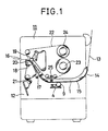
- FIG. 1 shows an overall view of a label printer 11. At the back of a housing 12, there is made an insertion opening 14 for inserting paper 13 therethrough. A paper transport path 15 is formed of a paper guide 1. At the front of the housing 12, there is made a paper discharge opening 16.
- the aforesaid paper 13 is that having ground paper in a long sheet form with rectangular labels stuck thereon at regular intervals. There are two modes of operation: one to issue the labels peeling them off the ground paper and the other to issue the labels as stuck on the ground paper.
- a paper sensor 17 Along the paper transport path 15, there are arranged a paper sensor 17, a platen 18, a thermal head 19, and a peeling plate 20, and below the peeling plate 20, there are provided a pair of ground paper feed rollers 21 for pulling the ground paper into the housing 12 when the labels are peeled off the same to be issued.
- a ribbon supply shaft 23 for retaining a printing ribbon 22 coiled into a roll and a ribbon take-up shaft 24 for retaining the printing ribbon 22 wound round.
- a ribbon sensor 25 between the ribbon supply shaft 23 and the ribbon take-up shaft 24, there is provided a ribbon sensor 25, whereby the printing ribbon 22 is aligned with its path so that it register with the paper 13 at the position between the platen 18 and the thermal head 19.
- a mount 4 and a skew roller 9 is mounted on the mount 4 through a mounting plate 7. Further, there is provided a roller opening lever 26 as a roller opening means with its one end fixed to the mounting plate 7. The other end of the roller opening lever 26 is prolonged to stick out in one direction.
- the end portion of the roller shaft 8 projects from the side plate 3 through a slit (not shown) made in the side plate 3 and held in abutment with an abutment surface 28 of a guide spring 27 as a skew roller position control means.
- the guide spring 27 is fixed at its one end to the side plate 3 and held at its free end portion in abutment with the end portion of the roller shaft 8. Below the abutment siirface 28 of the guide spring 27, there is a stopper edge 29 formed parallel to the paper guide 1.
- a release bar 30 as a releasing means fitted to the side plate 3 for axial movement with its axis in the direction perpendicular to the reference surface 2.
- the release bar 30 is provided with two stop rings 31, located at both sides of the side plate 3, for controlling its movement.
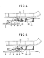
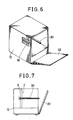
- the other end of the release bar 30 is located, as schematically shown in FIG. 6 and FIG. 7, at a position where it abuts against a cover 32 provided for the housing 12.
- the skew rollers 9 are held in a free state to push the paper 13 as shown in FIG. 3 and FIG. 4 thereby serving its intended function for preventing skew movement of the paper 13.
- the cover 32 When new paper 13 is to be set, the cover 32 is opened and the roller opening lever 26 is pressed down, whereby the roller shaft 8 holding the skew rollers 9 is also moved downward. While it moves down, the end portion of the roller shaft 8 descends sliding along the abutment surface 28 of the guide spring 27. When the distance of the descent reaches a predetermined value, the end portion of the roller shaft 8 comes off the abutment surface 28 and, hence, the guide spring 27 is moved by its own resilience toward the side of the skew rollers 9 and takes a position above the roller shaft 8 where it interferes with the roller shaft 8.
- the release lever 30 When setting of the paper 13 is thus finished, the release lever 30 is pushed in. Thereby, the guide spring 27 is pushed to move outward to reach the position at the end portion of the roller shaft 8, and then, the roller shaft 8 which has been restricted in movement by the stopper edge 29 is set free and allowed to rise by the force of the push-up spring 6, whereby the paper 13 comes to be pressed on. Then, even if the push on the release bar 30 is removed, the skew rollers 9 is not interfered in its movement only having the end portion of the roller shaft 30 put into abutment with the abutment surface 28 of the guide spring 27.
- FIG. 8 shows a variation of the present embodiment with the roller opening lever 26 omitted therefrom. More particularly, one end of the roller shaft 8 is prolonged so as to be gripped by hand and used as a roller opening means.
Applications Claiming Priority (2)
| Application Number | Priority Date | Filing Date | Title |
|---|---|---|---|
| JP37043/89 | 1989-02-16 | ||
| JP1037043A JPH07115774B2 (ja) | 1989-02-16 | 1989-02-16 | 用紙搬送装置 |
Publications (3)
| Publication Number | Publication Date |
|---|---|
| EP0383496A2 true EP0383496A2 (fr) | 1990-08-22 |
| EP0383496A3 EP0383496A3 (en) | 1990-12-05 |
| EP0383496B1 EP0383496B1 (fr) | 1993-09-22 |
Family
ID=12486573
Family Applications (1)
| Application Number | Title | Priority Date | Filing Date |
|---|---|---|---|
| EP90301397A Expired - Lifetime EP0383496B1 (fr) | 1989-02-16 | 1990-02-09 | Mécanisme de transport pour papier |
Country Status (6)
| Country | Link |
|---|---|
| US (1) | US4982946A (fr) |
| EP (1) | EP0383496B1 (fr) |
| JP (1) | JPH07115774B2 (fr) |
| KR (1) | KR920008592B1 (fr) |
| AU (1) | AU619385B2 (fr) |
| DE (1) | DE69003406T2 (fr) |
Cited By (1)
| Publication number | Priority date | Publication date | Assignee | Title |
|---|---|---|---|---|
| US5685471A (en) * | 1994-01-24 | 1997-11-11 | Oce Printing Systems Gmbh | Printing device with friction drive for processing strip-shaped recording substrates |
Families Citing this family (6)
| Publication number | Priority date | Publication date | Assignee | Title |
|---|---|---|---|---|
| US5278624A (en) * | 1992-07-07 | 1994-01-11 | Xerox Corporation | Differential drive for sheet registration drive rolls with skew detection |
| US5494277A (en) * | 1994-09-21 | 1996-02-27 | Lexmark International, Inc. | Universal paper feed |
| US20050109450A1 (en) * | 2003-11-25 | 2005-05-26 | Fargo Electronics, Inc. | Laminate feeding in a card manufacturing device |
| US7537211B2 (en) * | 2004-05-14 | 2009-05-26 | Seiko Epson Corporation | Media transportation mechanism and a data processing apparatus having a media transportation mechanism |
| US8146917B2 (en) * | 2008-10-09 | 2012-04-03 | Canon Kabushiki Kaisha | Conveying device with roller separating unit |
| JP5849511B2 (ja) * | 2011-08-11 | 2016-01-27 | セイコーエプソン株式会社 | 搬送装置および印刷装置 |
Citations (3)
| Publication number | Priority date | Publication date | Assignee | Title |
|---|---|---|---|---|
| DE2460318B2 (de) * | 1973-12-26 | 1981-04-02 | International Business Machines Corp., 10504 Armonk, N.Y. | Vorrichtung zur Aufnahme und Zuführung von einzelnen Blättern zu einem Vorratsbehälter hin und aus diesem heraus |
| DE3500986A1 (de) * | 1985-01-14 | 1986-07-17 | Nixdorf Computer Ag, 4790 Paderborn | Vorrichtung zur ein- und ausgabe von flaechigen aufzeichnungstraegern |
| US4676498A (en) * | 1982-12-10 | 1987-06-30 | Canon Kabushiki Kaisha | Sheet feeding apparatus |
Family Cites Families (4)
| Publication number | Priority date | Publication date | Assignee | Title |
|---|---|---|---|---|
| US4605218A (en) * | 1983-10-26 | 1986-08-12 | International Business Machines Corporation | Constant force roll assembly |
| DE8405504U1 (de) * | 1984-02-23 | 1984-05-30 | Kienzle Apparate Gmbh, 7730 Villingen-Schwenningen | Einfuehrschacht fuer belege in einem belegcodierer |
| JPS61266277A (ja) * | 1985-05-21 | 1986-11-25 | Tokyo Electric Co Ltd | サ−マル転写プリンタ |
| US4836527A (en) * | 1988-04-18 | 1989-06-06 | Xerox Corporation | Side edge registration system |
-
1989
- 1989-02-16 JP JP1037043A patent/JPH07115774B2/ja not_active Expired - Fee Related
-
1990
- 1990-02-09 US US07/477,479 patent/US4982946A/en not_active Expired - Lifetime
- 1990-02-09 DE DE90301397T patent/DE69003406T2/de not_active Expired - Fee Related
- 1990-02-09 EP EP90301397A patent/EP0383496B1/fr not_active Expired - Lifetime
- 1990-02-13 KR KR1019900001742A patent/KR920008592B1/ko not_active IP Right Cessation
- 1990-02-15 AU AU49803/90A patent/AU619385B2/en not_active Ceased
Patent Citations (3)
| Publication number | Priority date | Publication date | Assignee | Title |
|---|---|---|---|---|
| DE2460318B2 (de) * | 1973-12-26 | 1981-04-02 | International Business Machines Corp., 10504 Armonk, N.Y. | Vorrichtung zur Aufnahme und Zuführung von einzelnen Blättern zu einem Vorratsbehälter hin und aus diesem heraus |
| US4676498A (en) * | 1982-12-10 | 1987-06-30 | Canon Kabushiki Kaisha | Sheet feeding apparatus |
| DE3500986A1 (de) * | 1985-01-14 | 1986-07-17 | Nixdorf Computer Ag, 4790 Paderborn | Vorrichtung zur ein- und ausgabe von flaechigen aufzeichnungstraegern |
Cited By (1)
| Publication number | Priority date | Publication date | Assignee | Title |
|---|---|---|---|---|
| US5685471A (en) * | 1994-01-24 | 1997-11-11 | Oce Printing Systems Gmbh | Printing device with friction drive for processing strip-shaped recording substrates |
Also Published As
| Publication number | Publication date |
|---|---|
| JPH02215639A (ja) | 1990-08-28 |
| JPH07115774B2 (ja) | 1995-12-13 |
| DE69003406T2 (de) | 1994-05-11 |
| AU619385B2 (en) | 1992-01-23 |
| EP0383496A3 (en) | 1990-12-05 |
| AU4980390A (en) | 1990-08-30 |
| EP0383496B1 (fr) | 1993-09-22 |
| DE69003406D1 (de) | 1993-10-28 |
| US4982946A (en) | 1991-01-08 |
| KR920008592B1 (ko) | 1992-10-02 |
| KR900012770A (ko) | 1990-09-01 |
Similar Documents
| Publication | Publication Date | Title |
|---|---|---|
| EP1052107B1 (fr) | Imprimante thermique | |
| JP2697276B2 (ja) | プリンタ | |
| KR920008594B1 (ko) | 가격표용 써멀프린터의 써멀헤드 지지기구 | |
| EP0872352B1 (fr) | Dispositif d'enregistrement d'images comportant une cassette de bobine amovible | |
| JP2002144655A (ja) | プリンタ | |
| US4982946A (en) | Apparatus for transporting paper | |
| US4772146A (en) | Recording apparatus with a platen detachably incorporated therein | |
| US3977511A (en) | Ribbon loading device | |
| US5863139A (en) | Printing apparatus and a control method therefor | |
| EP0416802A1 (fr) | Dispositif de séparation dans une imprimante à étiquettes | |
| JP2690659B2 (ja) | ラベルプリンタ | |
| EP0272232A2 (fr) | Cartouche à ruban | |
| CA1265087A (fr) | Imprimante a double fonction | |
| IE47991B1 (en) | Apparatus for printing and/or applying self-adhesive labels | |
| JPH09115010A (ja) | 券処理装置及びその交換用インクリボン | |
| US5722653A (en) | Single-sheet feeder | |
| EP0795411A1 (fr) | Imprimante et sa méthode de commande | |
| JPH10139235A (ja) | 記録装置の排出機構 | |
| JP3012208B2 (ja) | 携帯型プリンタ | |
| CA2106646A1 (fr) | Appareil de positionnement et d'escamotage de butee d'enveloppe pour machine a affranchir thermique | |
| JPH11227953A (ja) | 印刷装置、シート収納マガジン及び印刷装置へのシート収納マガジンの装着装置 | |
| US6072515A (en) | Image marking device adapted to reduce an exterior envelope thereof | |
| JPS62936Y2 (fr) | ||
| JP2686997B2 (ja) | 紙送り装置 | |
| JPS5941286A (ja) | プリンタの用紙案内装置 |
Legal Events
| Date | Code | Title | Description |
|---|---|---|---|
| PUAI | Public reference made under article 153(3) epc to a published international application that has entered the european phase |
Free format text: ORIGINAL CODE: 0009012 |
|
| 17P | Request for examination filed |
Effective date: 19900221 |
|
| AK | Designated contracting states |
Kind code of ref document: A2 Designated state(s): BE DE FR GB NL SE |
|
| PUAL | Search report despatched |
Free format text: ORIGINAL CODE: 0009013 |
|
| AK | Designated contracting states |
Kind code of ref document: A3 Designated state(s): BE DE FR GB NL SE |
|
| RHK1 | Main classification (correction) |
Ipc: B65H 9/16 |
|
| 17Q | First examination report despatched |
Effective date: 19920707 |
|
| GRAA | (expected) grant |
Free format text: ORIGINAL CODE: 0009210 |
|
| AK | Designated contracting states |
Kind code of ref document: B1 Designated state(s): BE DE FR GB NL SE |
|
| REF | Corresponds to: |
Ref document number: 69003406 Country of ref document: DE Date of ref document: 19931028 |
|
| ET | Fr: translation filed | ||
| PLBE | No opposition filed within time limit |
Free format text: ORIGINAL CODE: 0009261 |
|
| STAA | Information on the status of an ep patent application or granted ep patent |
Free format text: STATUS: NO OPPOSITION FILED WITHIN TIME LIMIT |
|
| 26N | No opposition filed | ||
| EAL | Se: european patent in force in sweden |
Ref document number: 90301397.7 |
|
| PGFP | Annual fee paid to national office [announced via postgrant information from national office to epo] |
Ref country code: DE Payment date: 20010205 Year of fee payment: 12 |
|
| PGFP | Annual fee paid to national office [announced via postgrant information from national office to epo] |
Ref country code: SE Payment date: 20010206 Year of fee payment: 12 |
|
| PGFP | Annual fee paid to national office [announced via postgrant information from national office to epo] |
Ref country code: GB Payment date: 20010207 Year of fee payment: 12 |
|
| PGFP | Annual fee paid to national office [announced via postgrant information from national office to epo] |
Ref country code: FR Payment date: 20010213 Year of fee payment: 12 |
|
| PGFP | Annual fee paid to national office [announced via postgrant information from national office to epo] |
Ref country code: NL Payment date: 20010228 Year of fee payment: 12 |
|
| PGFP | Annual fee paid to national office [announced via postgrant information from national office to epo] |
Ref country code: BE Payment date: 20010427 Year of fee payment: 12 |
|
| REG | Reference to a national code |
Ref country code: GB Ref legal event code: IF02 |
|
| PG25 | Lapsed in a contracting state [announced via postgrant information from national office to epo] |
Ref country code: GB Free format text: LAPSE BECAUSE OF NON-PAYMENT OF DUE FEES Effective date: 20020209 |
|
| PG25 | Lapsed in a contracting state [announced via postgrant information from national office to epo] |
Ref country code: SE Free format text: LAPSE BECAUSE OF NON-PAYMENT OF DUE FEES Effective date: 20020210 |
|
| PG25 | Lapsed in a contracting state [announced via postgrant information from national office to epo] |
Ref country code: BE Free format text: LAPSE BECAUSE OF NON-PAYMENT OF DUE FEES Effective date: 20020228 |
|
| BERE | Be: lapsed |
Owner name: TOKYO ELECTRIC CO. LTD Effective date: 20020228 |
|
| PG25 | Lapsed in a contracting state [announced via postgrant information from national office to epo] |
Ref country code: NL Free format text: LAPSE BECAUSE OF NON-PAYMENT OF DUE FEES Effective date: 20020901 |
|
| PG25 | Lapsed in a contracting state [announced via postgrant information from national office to epo] |
Ref country code: DE Free format text: LAPSE BECAUSE OF NON-PAYMENT OF DUE FEES Effective date: 20020903 |
|
| EUG | Se: european patent has lapsed |
Ref document number: 90301397.7 |
|
| GBPC | Gb: european patent ceased through non-payment of renewal fee |
Effective date: 20020209 |
|
| PG25 | Lapsed in a contracting state [announced via postgrant information from national office to epo] |
Ref country code: FR Free format text: LAPSE BECAUSE OF NON-PAYMENT OF DUE FEES Effective date: 20021031 |
|
| NLV4 | Nl: lapsed or anulled due to non-payment of the annual fee |
Effective date: 20020901 |
|
| REG | Reference to a national code |
Ref country code: FR Ref legal event code: ST |