EP0190919B2 - Aufzeichnungssystem - Google Patents
Aufzeichnungssystem Download PDFInfo
- Publication number
- EP0190919B2 EP0190919B2 EP86300744A EP86300744A EP0190919B2 EP 0190919 B2 EP0190919 B2 EP 0190919B2 EP 86300744 A EP86300744 A EP 86300744A EP 86300744 A EP86300744 A EP 86300744A EP 0190919 B2 EP0190919 B2 EP 0190919B2
- Authority
- EP
- European Patent Office
- Prior art keywords
- signal
- video
- time
- signals
- recording
- Prior art date
- Legal status (The legal status is an assumption and is not a legal conclusion. Google has not performed a legal analysis and makes no representation as to the accuracy of the status listed.)
- Expired - Lifetime
Links
Images


Classifications
-
- H—ELECTRICITY
- H04—ELECTRIC COMMUNICATION TECHNIQUE
- H04N—PICTORIAL COMMUNICATION, e.g. TELEVISION
- H04N5/00—Details of television systems
- H04N5/76—Television signal recording
- H04N5/91—Television signal processing therefor
- H04N5/917—Television signal processing therefor for bandwidth reduction
- H04N5/919—Television signal processing therefor for bandwidth reduction by dividing samples or signal segments, e.g. television lines, among a plurality of recording channels
-
- H—ELECTRICITY
- H04—ELECTRIC COMMUNICATION TECHNIQUE
- H04N—PICTORIAL COMMUNICATION, e.g. TELEVISION
- H04N9/00—Details of colour television systems
- H04N9/79—Processing of colour television signals in connection with recording
- H04N9/797—Processing of colour television signals in connection with recording for recording the signal in a plurality of channels, the bandwidth of each channel being less than the bandwidth of the signal
- H04N9/7973—Processing of colour television signals in connection with recording for recording the signal in a plurality of channels, the bandwidth of each channel being less than the bandwidth of the signal by dividing the luminance or colour component signal samples or frequency bands among a plurality of recording channels
Definitions
- the invention relates in general to a recording system for video signals which are transmitted through a transmission line which has limited bandwidth.
- FIG. 1 illustrates a prior art system wherein an input terminal 101 receives an input signal which is connected to a time base compressor 102 which supplies an output to a recording amplifier 108 which supplies a signal to record/playback switch 9 that is connected to a rotary head 10 of a recorder to record the signal on a tape 11a.
- a signal is reproduced from the tape 11a by the rotary head 10 and is supplied through switch 9 which is placed in the reproduction position to supply the signal shown in FIG. 18D to a time base expander 113 which supplies an output through TBI circuit 118 to an output terminal 119.
- a sync amp 103, a PLL 104 and control 105 are connected between input terminal and time base compressor 102.
- a sync separator 114 and control 117 are connected between the switch 9 and time base expander 113.
- the prior art circuit is subject to jitter.
- the rotation of the rotary head is made to be twice its normal speed so as to increase the relative speed between the head and the tape, a video signal of wide band can be recorded.
- the heads are switched at, for example, the center of the vertical direction of the picture screen, if the characteristics of the head are unbalanced the quality of the picture will be changed in the upper and lower positions of the picture screen so that the picture is substantially degradated.
- FIG. 18A When there is a luminance signal Y illustrated, for example, in FIG. 18A and chrominance signals C 1 and C 2 of two systems as illustrated in FIGS. 18B and 18C, it is known as shown in FIG. 1 that the chrominance C 1 and C 2 are compressed in time-base during every horizontal period in a line sequential manner and inserted into the horizontal blanking period of the luminance signal Y and then transmitted as a single composite signal illustrated in FIG. 18D.
- a synchronizing signal (horizontal synchronizing HD) is inserted into the signal with the same polarity as the picture signal as is illustrated in FIG. 18D.
- the synchronizing signal cannot be detected and separated by level detection methods unlike, for example, an NTSC signal in the prior art but uses a frame synchronizing signal of a particular pattern which is inserted during every frame of a video signal and this pattern is detected so that on the basis of the frame synchronizing signal which is detected the horizontal synchronizing signal HD is detected at the timing of the horizontal period.
- TBC time-base correction
- the detection and separation of the synchronizing signal requires the above-described procedures and a substantial amount of time is required until the synchronizing signal is detected. Particularly, when a so-called servo-control of the video tape recorder is carried out on the basis of the synchronizing signal upon playback a large amount of lock-in time is required.
- the present invention relates to a recording system for a video signal in which a video signal is processed relative to its time base at every horizontal period and is alternately divided into two channels at every horizontal period and then recorded whereby a video signal having wide band can be recorded by a video tape recorder having narrow band.
- the present invention provides a recording system wherein at the recorder an input video signal provided with a horizontal synchronizing signal HD having a polarity which is the same as the picture signal during a horizontal period of said picture signal is supplied to an input terminal and is time-base expanded at every horizontal period and alternately separated to first and second channels at said unit of one horizontal line and the recording is carried out at every first and second channels and at the reproducing side the reproduced signals of said first and second channels are time-base processed and channel composed in a procedure which is opposite to those used at the recorder so as to obtain an output video signal which is the same as the original input signal wherein during recording a second horizontal synchronizing signal RH which has an opposite polarity to the picture signal and a burst signal RB are added to the signal and wherein during reproduction the second horizontal synchronizing signal is extracted by level detection and the burst signal is extracted by the second horizontal synchronizing signal and time-base errors of said picture signal and horizontal synchronizing signal are removed by using said extracted burst signal so as to reproduce an improved video
- the video signal since the video signal is processed for time base at every horizontal period and alternately separated to two channels at every horizontal period and then recorded, the video signal having wide band can be recorded and reproduced by the video tape recorder having narrow band and the quality of the picture will not be degradated or differ between the upper and lower portions of the picture screen.
- the present invention obtains a composite signal which is recorded and reproduced with a video tape recorder that provides satisfactory reproduced signal which will not have jitter.
- a second synchronizing signal and a burst signal which can be easily separated are added to the signal and during reproduction they are separated and then time-base errors are corrected so that a good video signal will be produced.
- FIG. 2 is a block diagram illustrating the embodiment of the invention wherein an input terminal 1 receives an input signal which is connected to a time base expander channel separator 2 which receives the input signal and separates it into two separate channels and supplies it to a pair of modulators 3a and 3b.
- Recording amplifiers 4a and 4b receive the output of the modulators 3a and 3b and respectively supply outputs to the recording heads 5a and 5b which record a signal on two separate channels on the tape 6.
- a pair of playback heads 7a and 7b, respectively, scan the channels recorded by the recording heads 5a and 5b and supply outputs to playback amplifiers 8a and 8b, respectively.
- Demodulators 9a and 9b receive the output of the playback amplifiers 8a and 8b and supply inputs to a time phase compressionichannel mixing circuit 10 which supplies an output to the output terminal 11.
- the video signal having, for example 1125 horizontal scanning lines is supplied to the input terminal 1.
- Such video signal is supplied to a time-base expansion/channel separation circuit 2 where it is separated to video signals of two separate channels to obtain video signals V 1 , V 2 , ... for each horizontal period and the waveforms are shown in FIG. 3A and are time-base expanded by a factor of 2 as illustrated in FIGS. 38 and 3C.
- the two channel video signals are independently reproduced from the recording tacks of the tape 6 by the playback heads 7a and 7b and amplified by the playback amplifiers 8a ad 8b and supplied to the demodulators 9a and 9b, respectively.
- the signals from the demodulators 9a and 9b are supplied to a time-base compressionichannel mixing circuit 10 where they are processed for time-base and channel mixed in a procedure which is opposite to the procedures used at the recording side and then supplied to the output terminal 11.
- the C/N ratio and S/N ratio can be improved by lowering the carrier of, for example, the FM recording.
- the input video signal is alternately separated into two channels at every horizontal period, even if the scattering of characteristics occur between the channels the difference between picture quality occurs at every horizontal scanning line and is prevented from becoming a difference between large picture screens. Thus, such differences can be prevented from being conspicuous and offensive to the viewer.
- the video signal is recorded and reproduced.
- the video signal since the video signal is processed on a time-based manner at the unit of every horizontal period and is alternately separated to two channels at a time-base of every horizontal period and then recorded, the video signal having wide bind can be recorded and reproduced by the video tape recorder which has narrow band and also it is possible to prevent the quality of the picture from being changed between the upper and lower portions of the picture screen.
- the video signal be subsampled which subsampling is completed in every four fields so as to compress the signal band.
- the video signal is formed from the signal of four fields which are stored in a memory by carrying out the data conversion and the interpolation at the sampling point as illustrated in FIG. 9.
- the distribution of such signals will be as illustrated in FIG. 13.
- the level of the signals fluctuate at every two lines in the vertical direction and this level fluctuation becomes a so-called vertical striped pattern and is very offensive to the eye.
- the channel separation is adjusted such that the relationship between the channel and the horizontal period is completed in one frame.
- the output signals from the video tape recorder become as shown in FIG. 5 at every field and when the signal are stored in the memory, the distribution of the signals becomes as shown in FIG. 6. If the signals are restored to the original signal by the above-mentioned data conversion interpolation, the distribution will be as shown in FIG. 7. Accordingly, as made clear from FIG. 7, the line crawl will be removed. In this case, although a horizontal striped pattern is produced, the horizontal stripe is not so offensive to the human eye as is the line crawl.
- the present invention provides an improved recording system and illustrates how to record for time compressed integration wherein during the first line one color signal is transmitted and during another line another color is transmitted. Signals are transmitted by FM period.
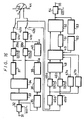
- FIG. 14 is a block diagram showing the structure of a recording and reproducing apparatus.
- a TCI signal which has the waveform illustrated in FIG. 15A is supplied to an input terminal 1 which supplies it to a time-base compressor circuit 102 and also to a sync separator circuit 103 in which a synchronizing signal is separated according to the previously mentioned procedures.
- the synchronizing signal thus separated is supplied to a PLL 104 (phase lock loop) in which a clock signal having a predetermined frequency is generated.
- This clock signal and the synchronizing signal are supplied to a control circuit 105 in which a timing signal is generated at every horizontal period containing the horizontal synchronizing signal HD, the chrominance signal C and the luminance signal Y.
- This timing signal is supplied to the time-base compressor circuit 102 in which the signal is compressed during one horizontal period with a predetermined ratio as illustrated in waveform of FIG. 15B. Also, the timing signal from the control circuit 105 is supplied to a generator circuit 106 in which a second horizontal synchronizing signal RH having a polarity which is opposite to the picture signal (the chrominance signal C and the luminance signal Y) is generated as well as a burst signal RB having a predetermined frequency and phase and are inserted into the signal into the space provided by the compression of the one horizontal period.
- the signal thus generated and the signal from the compressor circuit 102 are switched in a switch 107 by the timing signal from the control circuit 105 to generate a recording signal with a waveform which is illustrated in FIG. 15B.
- the signal is supplied through a recording circuit 108 through a record/playback changeover switching circuit 9 to the rotary head 10 of a recorder wherein the signal is recorded on a tape 11a.
- a signal is reproduced from the tape by the rotary head 10 and is supplied through the switch 9 which is moved to the reproduction position to supply the signal to the reproducing circuit 12.
- the reproduced signal will be equivalent to the signal shown in waveform of FIG. 15B, however, it contains a jitter component.
- This signal is supplied from the reproducing circuit 12 to a time-base expansion circuit 13 and also to a sync separator circuit 14 for separating the second horizontal synchronizing signal RH and also to a burst gate circuit 15 for separating the burst signal RB.
- the synchronizign signal separated by the sync separator 14 is fed to the burst gate 15 which separates the burst signal RB.
- the burst signal RB which has been extracted is supplied to a PLL 16 (phase lock loop) in which a clock signal of a predetermined frequency containing the previously mentioned jitter component is generated.
- the clock signal and the synchronizing signal are fed to a control circuit 17 in which a timing signal is generated at every horizontal period with the time-base being compressed.
- This timing signal is supplied to the time-base expansion circuit 13 in which during one horizontal period the signal is expanded so as to become identical to the original length illustrated in FIG. 15C.
- the signal of each horizontal period time-base which has been expanded is made continuous and is fed to a time-base corrector circuit 18 (DPC) and the clock signal from the PLL 16 is supplied to the TBC circuit 18 which generates the TCI signal (time compressed integrator) in which the jitter component has been removed and which has the waveform illustrated in FIG. 15C. This signal is supplied to the output terminal 19.
- DPC time-base corrector circuit 18
- the synchronizing signal can be easily separated and in a very short time by level detection or the like in the synchronizing separating circuit 14. Also, since the burst signal occurs in close proximity to the synchronizing signal, the burst signal can be easily and accurately extracted in the burst gate circuit 15 by delaying the synchronizing signal. Also, in the PLL circuit 16 the clock signal can easily and satisfactorily be generated by using the burst signal.
- the TCI signal is recorded and reproduced.
- the apparatus described above since during recording the second synchronizing signal and the burst signal which are easily separated are added to the video signal and during reproduction they are separated and the time-base correction and so on are accomplished, it is possible to reproduce satisfactory video signal very easily.
- a second synchronizing signal and the burst signal are added to the video signal such that they are inserted into the time space which is provided by the time-base compression of the picture signal although they may be added to the video signal by other methods.
- a part of the luminance signal could be removed into which the signals RH and RB are inserted.
- the frequency band width of the signal will be widened which requires a video tape recorder which has a wider band width than the transmission line.
- the recording and reproduction are accomplished with a video tape recorder having a narrow bandwidth.
- the recording and reproduction apparatus is applied through a system in which the signal is distributed into two channels during every one horizontal period then recorded and reproduced thus making the band width of the video tape recorder very narrow.
- FIG. 16 illustrates another embodiment and during recording a TCI signal is supplied to the input terminal 31 and is then supplied to an A/D converter circuit 32 in which it is digitized at a sampling frequency of, for example, 600f H (f H is the horizontal frequency).
- the digitized signal is supplied through an aperture compensation circuit 33 to a channel separation/time-base expansion circuit 34.
- the digitized signal is also supplied to a PLL clock generator circuit 35.
- the clock signal from the clock generator 35 is supplied to a timing control circuit 36.
- a signal having a waveform such as illustrated in FIG. 17A is expanded for example (20/11) times during every horizontal period and then there are generated signals of two channels that have a time spacing between their respective horizontal periods as illustrated in FIGS.
- a delay circuit 37 having a delay time equal to the timing distance between the two heads plus 0.5H (H is the horizontal period).
- the delay circuit 37 is in the channel of the first recording head as illustrated. Then adjacent horizontal periods are recroded on the tape at adjacent track portions.
- a digital burst signal RB is generated by a generator circuit 38 and is inserted into each of the two signals.
- the burst signals are inserted, respectively, into D/A converter circuits 39a and 39b in which the signals are converted to analog signals at a sampling frequency of 330f H .
- a second horizontal synchronizing signal RH having a polarity which is opposite to the picture signal and which is derived from a synchronizing generator circuit 40 is inserted into the analog signals as illustrated.
- These signals are supplied through recording circuits 41a and 41b to a rotary recording head 43 which has two pairs, in other words, four heads so that the recording is carried out such that each of the channels is formed into a track on a tape 44 and the video signals of one field is formed by two tracks.
- the signals reproduced from the tape 44 by the rotary head 44 are supplied through the switches 42a and 42b to the reproducing circuits 45a and 45b. These signals are equivalent to the signal shown in the waveform diagram of FIG. 17D but contain jitter component. These signals are respectively supplied to A/D converter circuits 46a and 46b and are digitized at the sampling frequency of 330f H . The signals from the reproducing circuits 45a and 45b are also supplied to PLL clock generator circuits 47a and 47b in which clock signals having predetermined frequencies and containing the jitter components are respectively generated.
- the signals from the A/D converter circuits 46a and 46b are supplied through a dropout compensating circuit 48 to a time-base correction circuit (TBC) 49 and the clock signals from the generator circuits 47a and 47b are supplied to the time-base corrector circuit 49.
- TBC time-base correction circuit
- a signal from a timing-control circuit 50 is supplied to the time-base corrector circuit 49 and time-base correction of the reproduced signal is accomplished.
- a delay circuit 51 so as to correct the delay caused by the delay circuit 37 used in the recording mode.
- the corrected signals are supplied to a channel mixing/time-base compressor circuit 52 in which the signal is compressed for time-base and mixed with a reverse operation to that of the expansion circuit 34 used in the recording mode.
- a digital frame synchronizing signal from a generator cricuit 53 is inserted into the signal and then fed to a D/A converter circuit 54 in which it is converted to an analog signal at a sampling frequency of 600fH to generate a TCI signal in which the jitter component has been removed. This signal is delivered to the output terminal 55.
- the frequency band is made narrower by the expansion of the time-base during recording so that the recording and reproducing can be carried out using a video tape recorder having narrow band width.
- the second synchronizing signal and the burst signal which are easily separated are added to the video signal and during reproducing they are separated and are corrected for time-base and similar effects a satisfactory video signal can be easily reproduced.
Landscapes
- Engineering & Computer Science (AREA)
- Multimedia (AREA)
- Signal Processing (AREA)
- Television Signal Processing For Recording (AREA)
Claims (3)
- Gerät zur Aufzeichnung und zur Wiedergabe eines zeitkomprimierten Videosignalgemischs, das in jeder horizontalen Periode des Bildsignals ein horizontales Synchronisiersignal enthält, das dieselbe Polarität hat wie das Bildsignal, wobei das Gerät aufweisteine Expandiereinrichtung zur zeitlichen Dehnung eines Eingangssignals in jeder Zeilenperiode,eine Trenneinrichtung zum Auftrennen aufeinanderfolgender Zeilen des zeltgedehnten Eingangssignals abwechselnd in einen ersten und einen zweiten Kanal,einen ersten und einen zweiten Videokopf zum Aufzeichnen und Wiedergeben der Signale aus dem ersten und dem zweiten Videokanal auf bzw. von unterschiedlichen Spuren eines Videobandes,eine Verarbeitungseinrichtung mit einer Zeitbasis-Kompressionsschaltung zur Verarbeitung des aufgezeichneten Signals undeine Kanalmischschaltung zur Gewinnung eines Ausgangsvideosignals,dadurch gekennzeichnet, daß das Gerät ferner aufweist:eine Addiereinrichtung zum Addieren eines Burstsignals und eines zweiten horizontalen Synchronisiersignals mit zur Polarität des Bildsignals entgegengesetzter Polarität zu dem Signal in jedem Kanal, bevor dieses aufgezeichnet wird, undeine Extrahiereinrichtung zum Extrahieren des zweiten horizontalen Synchronisiersignals und des Burstsignals aus dem reproduzierten Signal, wobei das Burstsignal, das extrahiert wurde, zum Entfernen von Zeitbasisfehlers in dem Bildsignal und dem horizontalen Synchronisiersignal verwendet wird.
- Gerät nach Anspruch 1 mit einem Paar von Taktgeneratoren, die die Signale aus dem ersten und dem zweiten Videokanal aufnehmen und Eingangssignale an die Zeitbasis-Kompressionsschaltung liefern, sowie mit einer Zeitsteuerung zur Zuführung eines Eingangssignals an die Zeitbasis-Kompressionsschaltung.
- Gerät nach Anspruch 1 oder 2 mit einem Rahmen-Synchronisiergenerator, der so angeordnet ist, daß er ein Einqangssignal an die Kanalmischschaltung und an die Zeitbasis-Kompressionsschaltung liefert.
Priority Applications (1)
| Application Number | Priority Date | Filing Date | Title |
|---|---|---|---|
| AT86300744T ATE69131T1 (de) | 1985-02-05 | 1986-02-04 | Aufzeichnungssystem. |
Applications Claiming Priority (4)
| Application Number | Priority Date | Filing Date | Title |
|---|---|---|---|
| JP20683/85 | 1985-02-05 | ||
| JP60020683A JPH0720227B2 (ja) | 1985-02-05 | 1985-02-05 | 記録再生装置 |
| JP60027423A JPH0752938B2 (ja) | 1985-02-14 | 1985-02-14 | 記録装置及び記録再生装置 |
| JP27423/85 | 1985-02-14 |
Publications (4)
| Publication Number | Publication Date |
|---|---|
| EP0190919A2 EP0190919A2 (de) | 1986-08-13 |
| EP0190919A3 EP0190919A3 (en) | 1987-12-16 |
| EP0190919B1 EP0190919B1 (de) | 1991-10-30 |
| EP0190919B2 true EP0190919B2 (de) | 1996-12-27 |
Family
ID=26357654
Family Applications (1)
| Application Number | Title | Priority Date | Filing Date |
|---|---|---|---|
| EP86300744A Expired - Lifetime EP0190919B2 (de) | 1985-02-05 | 1986-02-04 | Aufzeichnungssystem |
Country Status (3)
| Country | Link |
|---|---|
| US (1) | US4780769A (de) |
| EP (1) | EP0190919B2 (de) |
| DE (1) | DE3682217D1 (de) |
Families Citing this family (19)
| Publication number | Priority date | Publication date | Assignee | Title |
|---|---|---|---|---|
| US4839744A (en) * | 1986-09-01 | 1989-06-13 | Nippon Hoso Kyokai | Video signal recording method and associated recording/reproducing apparatus |
| GB2199982B (en) * | 1987-01-14 | 1991-09-11 | Rca Corp | Segmented tape format video tape system |
| EP0332381A1 (de) * | 1988-03-08 | 1989-09-13 | Matsushita Electric Industrial Co., Ltd. | Aufzeichnungs- und Wiedergabegerät für Videosignale |
| JPH01245470A (ja) * | 1988-03-28 | 1989-09-29 | Toshiba Corp | 回転ヘッド型磁気記録再生装置 |
| FR2630281B1 (fr) * | 1988-04-19 | 1990-08-17 | France Etat | Procede de diffusion de programmes de television derive du type mac/paquets, et installation de mise en oeuvre du procede |
| NL8801513A (nl) * | 1988-06-14 | 1990-01-02 | Philips Nv | Inrichting voor het opnemen of weergeven van een elektrisch signaal op/van een magnetische registratiedrager. |
| FR2636801B1 (fr) * | 1988-09-21 | 1990-10-26 | France Etat | Procede d'enregistrement sur bande magnetique et de lecture de signaux d2-mac/paquet |
| FR2651949B1 (fr) * | 1989-09-13 | 1991-10-25 | France Etat | Procede d'enregistrement et de lecture de signaux de television a haute definition. |
| JP2522580B2 (ja) * | 1990-04-06 | 1996-08-07 | シャープ株式会社 | 映像信号記録再生装置 |
| KR970004688B1 (ko) * | 1990-04-28 | 1997-04-02 | 상요 덴기 가부시끼가이샤 | 고품위 양면 비디오 디스크 및 이의 제조방법 |
| JPH04104690A (ja) * | 1990-08-24 | 1992-04-07 | Sony Corp | 記録方法 |
| JPH04188979A (ja) * | 1990-11-21 | 1992-07-07 | Sharp Corp | 映像信号記録装置 |
| US5091774A (en) * | 1990-11-30 | 1992-02-25 | Eastman Kodak Company | Method and apparatus for providing sync on R-G-B video signals |
| GB2257868B (en) * | 1991-07-16 | 1995-04-12 | Asahi Optical Co Ltd | Still video device |
| US5594553A (en) * | 1992-09-04 | 1997-01-14 | Asahi Kogaku Kogyo Kabushiki Kaisha | Video signal recording and reproducing apparatus using signal modification to remove jitter |
| JP3260172B2 (ja) * | 1992-09-04 | 2002-02-25 | 旭光学工業株式会社 | 映像信号記録再生装置 |
| US5289277A (en) * | 1992-11-05 | 1994-02-22 | Zenith Electronics Corp. | High definition television signal format converter |
| US5469325A (en) * | 1993-03-22 | 1995-11-21 | Evans Findings Co. | Capacitor |
| US5784122A (en) * | 1995-06-21 | 1998-07-21 | Sony Corporation | Chroma lock detector |
Family Cites Families (14)
| Publication number | Priority date | Publication date | Assignee | Title |
|---|---|---|---|---|
| US3809805A (en) * | 1972-08-25 | 1974-05-07 | Arvin Ind Inc | Video bandwidth reduction |
| JPS5914948B2 (ja) * | 1976-01-21 | 1984-04-06 | 株式会社日立製作所 | カラ−テレビジヨン信号処理方式 |
| DE2745337C2 (de) * | 1977-10-08 | 1986-04-17 | Robert Bosch Gmbh, 7000 Stuttgart | Verfahren zum Speichern von breitbandigen Signalen |
| JPS5817504A (ja) * | 1981-07-22 | 1983-02-01 | Olympus Optical Co Ltd | 情報記録再生装置 |
| US4520401A (en) * | 1982-04-16 | 1985-05-28 | Victor Company Of Japan, Ltd. | Digital video signal recording system and reproducing apparatus |
| JPS58185009A (ja) * | 1982-04-23 | 1983-10-28 | Sony Corp | 磁気記録再生装置 |
| EP0114694B1 (de) * | 1983-01-25 | 1988-05-18 | Robert Bosch Gmbh | System zur Übertragung eines breitbandigen Farbvideosignals |
| JPS59146288A (ja) * | 1983-02-09 | 1984-08-22 | Victor Co Of Japan Ltd | カラ−映像信号の記録信号の生成方式 |
| JPS59172897A (ja) * | 1983-03-22 | 1984-09-29 | Victor Co Of Japan Ltd | カラ−映像信号再生装置におけるクロツクパルス発生回路 |
| CA1241739A (en) * | 1983-04-22 | 1988-09-06 | Takeshi Ninomiya | Magnetic recording and reproducing apparatus for recording and reproducing a video signal obtained from a high speed scanning video camera |
| EP0168834B2 (de) * | 1984-07-20 | 1996-11-06 | Hitachi, Ltd. | Verfahren und Gerät zum Aufzeichnen und Wiedergeben von Videosignalen |
| JPS6169287A (ja) * | 1984-09-12 | 1986-04-09 | Sony Corp | 時間軸補正装置 |
| JPH0712229B2 (ja) * | 1984-12-25 | 1995-02-08 | ソニー株式会社 | 時間軸補正装置 |
| US4688081A (en) * | 1985-01-25 | 1987-08-18 | Hitachi, Ltd. | Apparatus for correcting time base error of video signal |
-
1986
- 1986-02-04 EP EP86300744A patent/EP0190919B2/de not_active Expired - Lifetime
- 1986-02-04 DE DE8686300744T patent/DE3682217D1/de not_active Expired - Lifetime
- 1986-02-04 US US06/826,026 patent/US4780769A/en not_active Expired - Lifetime
Also Published As
| Publication number | Publication date |
|---|---|
| DE3682217D1 (de) | 1991-12-05 |
| EP0190919B1 (de) | 1991-10-30 |
| EP0190919A3 (en) | 1987-12-16 |
| US4780769A (en) | 1988-10-25 |
| EP0190919A2 (de) | 1986-08-13 |
Similar Documents
| Publication | Publication Date | Title |
|---|---|---|
| EP0190919B2 (de) | Aufzeichnungssystem | |
| KR870000884B1 (ko) | 칼라 영상신호 재생장치의 클럭펄스 발생회로 | |
| US5245430A (en) | Timebase corrector with drop-out compensation | |
| US4630131A (en) | Recording signal generation system for color video signal | |
| US4608609A (en) | Apparatus for recording a color video signal | |
| US4090215A (en) | Electronic time base error correction methods and arrangements | |
| KR930011981B1 (ko) | 영상신호의 재생장치 | |
| JPS59171285A (ja) | 映像信号のドロツプアウト補償回路 | |
| EP0278733B1 (de) | Vorrichtung für die Aufnahme und Wiedergabe eines Videosignals | |
| JPH06101855B2 (ja) | ビデオ信号変換装置 | |
| KR100248931B1 (ko) | 시간축 보정장치의 크램프장치 | |
| JPS59172898A (ja) | カラ−映像信号再生装置におけるクロツクパルス発生回路 | |
| JPH0752962B2 (ja) | カラー映像信号の記録再生方法 | |
| EP0479135B1 (de) | Vorrichtung zum Verarbeiten eines Bildsignals | |
| EP0418569B1 (de) | Bildsignalwiedergabevorrichtung | |
| KR890003519B1 (ko) | 기록재생장치 | |
| KR100236134B1 (ko) | 시간축 보정장치 | |
| JP2616019B2 (ja) | 記録再生装置 | |
| JPS63203076A (ja) | Vtrの文字信号表示回路 | |
| EP0444699A2 (de) | Videosignalaufzeichnungsvorrichtung | |
| JPH0720227B2 (ja) | 記録再生装置 | |
| JPH04314296A (ja) | 再生信号検出回路 | |
| JPS60224389A (ja) | 映像信号記録方式 | |
| EP0484144A2 (de) | Verfahren und Vorrichtung zur Verarbeitung eines Videosignals | |
| JPS61184085A (ja) | 映像信号処理方法 |
Legal Events
| Date | Code | Title | Description |
|---|---|---|---|
| PUAI | Public reference made under article 153(3) epc to a published international application that has entered the european phase |
Free format text: ORIGINAL CODE: 0009012 |
|
| 17P | Request for examination filed |
Effective date: 19860214 |
|
| AK | Designated contracting states |
Kind code of ref document: A2 Designated state(s): AT DE FR GB IT NL |
|
| PUAL | Search report despatched |
Free format text: ORIGINAL CODE: 0009013 |
|
| RHK1 | Main classification (correction) |
Ipc: H04N 9/82 |
|
| AK | Designated contracting states |
Kind code of ref document: A3 Designated state(s): AT DE FR GB IT NL |
|
| 17Q | First examination report despatched |
Effective date: 19900322 |
|
| GRAA | (expected) grant |
Free format text: ORIGINAL CODE: 0009210 |
|
| AK | Designated contracting states |
Kind code of ref document: B1 Designated state(s): AT DE FR GB IT NL |
|
| REF | Corresponds to: |
Ref document number: 69131 Country of ref document: AT Date of ref document: 19911115 Kind code of ref document: T |
|
| REF | Corresponds to: |
Ref document number: 3682217 Country of ref document: DE Date of ref document: 19911205 |
|
| ET | Fr: translation filed | ||
| ITF | It: translation for a ep patent filed | ||
| PLBI | Opposition filed |
Free format text: ORIGINAL CODE: 0009260 |
|
| 26 | Opposition filed |
Opponent name: INTERESSENGEMEINSCHAFT FUER RUNDFUNKSCHUTZRECHTE E Effective date: 19920728 |
|
| NLR1 | Nl: opposition has been filed with the epo |
Opponent name: INTERESSENGEMEINSCHAFT FUR RUNDFUNKSCHUTZRECHTE E. |
|
| PLAB | Opposition data, opponent's data or that of the opponent's representative modified |
Free format text: ORIGINAL CODE: 0009299OPPO |
|
| R26 | Opposition filed (corrected) |
Opponent name: INTERESSENGEMEINSCHAFT FUER RUNDFUNKSCHUTZRECHTE E Effective date: 19920728 |
|
| NLR1 | Nl: opposition has been filed with the epo |
Opponent name: INTERESSENGEMEINSCHAFT FUER RUNDFUNKSCHUTZRECHTE E |
|
| PLAW | Interlocutory decision in opposition |
Free format text: ORIGINAL CODE: EPIDOS IDOP |
|
| PLAW | Interlocutory decision in opposition |
Free format text: ORIGINAL CODE: EPIDOS IDOP |
|
| PUAH | Patent maintained in amended form |
Free format text: ORIGINAL CODE: 0009272 |
|
| STAA | Information on the status of an ep patent application or granted ep patent |
Free format text: STATUS: PATENT MAINTAINED AS AMENDED |
|
| 27A | Patent maintained in amended form |
Effective date: 19961227 |
|
| AK | Designated contracting states |
Kind code of ref document: B2 Designated state(s): AT DE FR GB IT NL |
|
| ITF | It: translation for a ep patent filed | ||
| NLR2 | Nl: decision of opposition | ||
| ET3 | Fr: translation filed ** decision concerning opposition | ||
| NLR3 | Nl: receipt of modified translations in the netherlands language after an opposition procedure | ||
| REG | Reference to a national code |
Ref country code: GB Ref legal event code: IF02 |
|
| PGFP | Annual fee paid to national office [announced via postgrant information from national office to epo] |
Ref country code: GB Payment date: 20020206 Year of fee payment: 17 |
|
| PGFP | Annual fee paid to national office [announced via postgrant information from national office to epo] |
Ref country code: FR Payment date: 20020212 Year of fee payment: 17 |
|
| PGFP | Annual fee paid to national office [announced via postgrant information from national office to epo] |
Ref country code: AT Payment date: 20020213 Year of fee payment: 17 |
|
| PGFP | Annual fee paid to national office [announced via postgrant information from national office to epo] |
Ref country code: DE Payment date: 20020227 Year of fee payment: 17 |
|
| PGFP | Annual fee paid to national office [announced via postgrant information from national office to epo] |
Ref country code: NL Payment date: 20020228 Year of fee payment: 17 |
|
| PG25 | Lapsed in a contracting state [announced via postgrant information from national office to epo] |
Ref country code: GB Free format text: LAPSE BECAUSE OF NON-PAYMENT OF DUE FEES Effective date: 20030204 Ref country code: AT Free format text: LAPSE BECAUSE OF NON-PAYMENT OF DUE FEES Effective date: 20030204 |
|
| PG25 | Lapsed in a contracting state [announced via postgrant information from national office to epo] |
Ref country code: NL Free format text: LAPSE BECAUSE OF NON-PAYMENT OF DUE FEES Effective date: 20030901 |
|
| PG25 | Lapsed in a contracting state [announced via postgrant information from national office to epo] |
Ref country code: DE Free format text: LAPSE BECAUSE OF NON-PAYMENT OF DUE FEES Effective date: 20030902 |
|
| GBPC | Gb: european patent ceased through non-payment of renewal fee | ||
| PG25 | Lapsed in a contracting state [announced via postgrant information from national office to epo] |
Ref country code: FR Free format text: LAPSE BECAUSE OF NON-PAYMENT OF DUE FEES Effective date: 20031031 |
|
| NLV4 | Nl: lapsed or anulled due to non-payment of the annual fee |
Effective date: 20030901 |
|
| REG | Reference to a national code |
Ref country code: FR Ref legal event code: ST |
|
| PG25 | Lapsed in a contracting state [announced via postgrant information from national office to epo] |
Ref country code: IT Free format text: LAPSE BECAUSE OF NON-PAYMENT OF DUE FEES;WARNING: LAPSES OF ITALIAN PATENTS WITH EFFECTIVE DATE BEFORE 2007 MAY HAVE OCCURRED AT ANY TIME BEFORE 2007. THE CORRECT EFFECTIVE DATE MAY BE DIFFERENT FROM THE ONE RECORDED. Effective date: 20050204 |