EP0188951B1 - Procédé de montage d'un ensemble de pièces sur un organe support, notamment les pièces d'une commande de distribution d'un moteur thermique, et empreinte de conditionnement pour la mise en oeuvre de ce procédé - Google Patents
Procédé de montage d'un ensemble de pièces sur un organe support, notamment les pièces d'une commande de distribution d'un moteur thermique, et empreinte de conditionnement pour la mise en oeuvre de ce procédé Download PDFInfo
- Publication number
- EP0188951B1 EP0188951B1 EP85402541A EP85402541A EP0188951B1 EP 0188951 B1 EP0188951 B1 EP 0188951B1 EP 85402541 A EP85402541 A EP 85402541A EP 85402541 A EP85402541 A EP 85402541A EP 0188951 B1 EP0188951 B1 EP 0188951B1
- Authority
- EP
- European Patent Office
- Prior art keywords
- mould
- component parts
- parts
- support element
- engine
- Prior art date
- Legal status (The legal status is an assumption and is not a legal conclusion. Google has not performed a legal analysis and makes no representation as to the accuracy of the status listed.)
- Expired
Links
Images

Classifications
-
- F—MECHANICAL ENGINEERING; LIGHTING; HEATING; WEAPONS; BLASTING
- F16—ENGINEERING ELEMENTS AND UNITS; GENERAL MEASURES FOR PRODUCING AND MAINTAINING EFFECTIVE FUNCTIONING OF MACHINES OR INSTALLATIONS; THERMAL INSULATION IN GENERAL
- F16H—GEARING
- F16H7/00—Gearings for conveying rotary motion by endless flexible members
- F16H7/08—Means for varying tension of belts, ropes or chains
-
- B—PERFORMING OPERATIONS; TRANSPORTING
- B23—MACHINE TOOLS; METAL-WORKING NOT OTHERWISE PROVIDED FOR
- B23P—METAL-WORKING NOT OTHERWISE PROVIDED FOR; COMBINED OPERATIONS; UNIVERSAL MACHINE TOOLS
- B23P19/00—Machines for simply fitting together or separating metal parts or objects, or metal and non-metal parts, whether or not involving some deformation; Tools or devices therefor so far as not provided for in other classes
-
- B—PERFORMING OPERATIONS; TRANSPORTING
- B65—CONVEYING; PACKING; STORING; HANDLING THIN OR FILAMENTARY MATERIAL
- B65D—CONTAINERS FOR STORAGE OR TRANSPORT OF ARTICLES OR MATERIALS, e.g. BAGS, BARRELS, BOTTLES, BOXES, CANS, CARTONS, CRATES, DRUMS, JARS, TANKS, HOPPERS, FORWARDING CONTAINERS; ACCESSORIES, CLOSURES, OR FITTINGS THEREFOR; PACKAGING ELEMENTS; PACKAGES
- B65D85/00—Containers, packaging elements or packages, specially adapted for particular articles or materials
- B65D85/68—Containers, packaging elements or packages, specially adapted for particular articles or materials for machines, engines or vehicles in assembled or dismantled form
-
- F—MECHANICAL ENGINEERING; LIGHTING; HEATING; WEAPONS; BLASTING
- F01—MACHINES OR ENGINES IN GENERAL; ENGINE PLANTS IN GENERAL; STEAM ENGINES
- F01L—CYCLICALLY OPERATING VALVES FOR MACHINES OR ENGINES
- F01L1/00—Valve-gear or valve arrangements, e.g. lift-valve gear
- F01L1/02—Valve drive
-
- F—MECHANICAL ENGINEERING; LIGHTING; HEATING; WEAPONS; BLASTING
- F01—MACHINES OR ENGINES IN GENERAL; ENGINE PLANTS IN GENERAL; STEAM ENGINES
- F01L—CYCLICALLY OPERATING VALVES FOR MACHINES OR ENGINES
- F01L1/00—Valve-gear or valve arrangements, e.g. lift-valve gear
- F01L1/02—Valve drive
- F01L1/022—Chain drive
-
- F—MECHANICAL ENGINEERING; LIGHTING; HEATING; WEAPONS; BLASTING
- F01—MACHINES OR ENGINES IN GENERAL; ENGINE PLANTS IN GENERAL; STEAM ENGINES
- F01L—CYCLICALLY OPERATING VALVES FOR MACHINES OR ENGINES
- F01L1/00—Valve-gear or valve arrangements, e.g. lift-valve gear
- F01L1/02—Valve drive
- F01L1/024—Belt drive
-
- F—MECHANICAL ENGINEERING; LIGHTING; HEATING; WEAPONS; BLASTING
- F01—MACHINES OR ENGINES IN GENERAL; ENGINE PLANTS IN GENERAL; STEAM ENGINES
- F01L—CYCLICALLY OPERATING VALVES FOR MACHINES OR ENGINES
- F01L1/00—Valve-gear or valve arrangements, e.g. lift-valve gear
- F01L1/46—Component parts, details, or accessories, not provided for in preceding subgroups
-
- F—MECHANICAL ENGINEERING; LIGHTING; HEATING; WEAPONS; BLASTING
- F16—ENGINEERING ELEMENTS AND UNITS; GENERAL MEASURES FOR PRODUCING AND MAINTAINING EFFECTIVE FUNCTIONING OF MACHINES OR INSTALLATIONS; THERMAL INSULATION IN GENERAL
- F16H—GEARING
- F16H7/00—Gearings for conveying rotary motion by endless flexible members
- F16H7/18—Means for guiding or supporting belts, ropes, or chains
-
- B—PERFORMING OPERATIONS; TRANSPORTING
- B65—CONVEYING; PACKING; STORING; HANDLING THIN OR FILAMENTARY MATERIAL
- B65D—CONTAINERS FOR STORAGE OR TRANSPORT OF ARTICLES OR MATERIALS, e.g. BAGS, BARRELS, BOTTLES, BOXES, CANS, CARTONS, CRATES, DRUMS, JARS, TANKS, HOPPERS, FORWARDING CONTAINERS; ACCESSORIES, CLOSURES, OR FITTINGS THEREFOR; PACKAGING ELEMENTS; PACKAGES
- B65D2585/00—Containers, packaging elements or packages specially adapted for particular articles or materials
- B65D2585/68—Containers, packaging elements or packages specially adapted for particular articles or materials for machines, engines, or vehicles in assembled or dismantled form
- B65D2585/6802—Containers, packaging elements or packages specially adapted for particular articles or materials for machines, engines, or vehicles in assembled or dismantled form specific machines, engines or vehicles
- B65D2585/6875—Containers, packaging elements or packages specially adapted for particular articles or materials for machines, engines, or vehicles in assembled or dismantled form specific machines, engines or vehicles engines, motors, machines and vehicle parts
- B65D2585/6877—Containers, packaging elements or packages specially adapted for particular articles or materials for machines, engines, or vehicles in assembled or dismantled form specific machines, engines or vehicles engines, motors, machines and vehicle parts engines or motors
-
- B—PERFORMING OPERATIONS; TRANSPORTING
- B65—CONVEYING; PACKING; STORING; HANDLING THIN OR FILAMENTARY MATERIAL
- B65D—CONTAINERS FOR STORAGE OR TRANSPORT OF ARTICLES OR MATERIALS, e.g. BAGS, BARRELS, BOTTLES, BOXES, CANS, CARTONS, CRATES, DRUMS, JARS, TANKS, HOPPERS, FORWARDING CONTAINERS; ACCESSORIES, CLOSURES, OR FITTINGS THEREFOR; PACKAGING ELEMENTS; PACKAGES
- B65D2585/00—Containers, packaging elements or packages specially adapted for particular articles or materials
- B65D2585/68—Containers, packaging elements or packages specially adapted for particular articles or materials for machines, engines, or vehicles in assembled or dismantled form
- B65D2585/6802—Containers, packaging elements or packages specially adapted for particular articles or materials for machines, engines, or vehicles in assembled or dismantled form specific machines, engines or vehicles
- B65D2585/6875—Containers, packaging elements or packages specially adapted for particular articles or materials for machines, engines, or vehicles in assembled or dismantled form specific machines, engines or vehicles engines, motors, machines and vehicle parts
- B65D2585/6882—Containers, packaging elements or packages specially adapted for particular articles or materials for machines, engines, or vehicles in assembled or dismantled form specific machines, engines or vehicles engines, motors, machines and vehicle parts vehicle parts
-
- F—MECHANICAL ENGINEERING; LIGHTING; HEATING; WEAPONS; BLASTING
- F01—MACHINES OR ENGINES IN GENERAL; ENGINE PLANTS IN GENERAL; STEAM ENGINES
- F01L—CYCLICALLY OPERATING VALVES FOR MACHINES OR ENGINES
- F01L2303/00—Manufacturing of components used in valve arrangements
- F01L2303/01—Tools for producing, mounting or adjusting, e.g. some part of the distribution
-
- F—MECHANICAL ENGINEERING; LIGHTING; HEATING; WEAPONS; BLASTING
- F16—ENGINEERING ELEMENTS AND UNITS; GENERAL MEASURES FOR PRODUCING AND MAINTAINING EFFECTIVE FUNCTIONING OF MACHINES OR INSTALLATIONS; THERMAL INSULATION IN GENERAL
- F16H—GEARING
- F16H7/00—Gearings for conveying rotary motion by endless flexible members
- F16H7/08—Means for varying tension of belts, ropes or chains
- F16H2007/0802—Actuators for final output members
- F16H2007/0806—Compression coil springs
-
- F—MECHANICAL ENGINEERING; LIGHTING; HEATING; WEAPONS; BLASTING
- F16—ENGINEERING ELEMENTS AND UNITS; GENERAL MEASURES FOR PRODUCING AND MAINTAINING EFFECTIVE FUNCTIONING OF MACHINES OR INSTALLATIONS; THERMAL INSULATION IN GENERAL
- F16H—GEARING
- F16H7/00—Gearings for conveying rotary motion by endless flexible members
- F16H7/08—Means for varying tension of belts, ropes or chains
- F16H2007/0802—Actuators for final output members
- F16H2007/0812—Fluid pressure
-
- F—MECHANICAL ENGINEERING; LIGHTING; HEATING; WEAPONS; BLASTING
- F16—ENGINEERING ELEMENTS AND UNITS; GENERAL MEASURES FOR PRODUCING AND MAINTAINING EFFECTIVE FUNCTIONING OF MACHINES OR INSTALLATIONS; THERMAL INSULATION IN GENERAL
- F16H—GEARING
- F16H7/00—Gearings for conveying rotary motion by endless flexible members
- F16H7/08—Means for varying tension of belts, ropes or chains
- F16H2007/0863—Finally actuated members, e.g. constructional details thereof
- F16H2007/0872—Sliding members
Definitions
- the present invention relates to a method of mounting a set of parts on a support member in determined relative positions and orientations, in particular the parts of a distribution control of a heat engine (see for example EP-A-0124 433 ), as well as a packaging imprint for the implementation of this process.
- crankshaft pinion is mounted, then the tensioning and guide element (s), then the shaft wheel and finally the transmission element, consisting of a chain or a belt, is placed.
- the invention therefore aims to remedy these constraints and disadvantages by proposing a method of mounting the parts on the support, as well as an imprint or packaging for the implementation of this method, which substantially improves the productivity and reliability in mounting the various parts of the assembly.
- the mounting method is characterized in that the parts are placed in an impression or they are prepositioned, preoriented and maintained in positions corresponding to those which they must occupy on their support member, then this impression, with the parts housed therein, in front of the support member in the appropriate orientation, said pieces are fixed on the support member without extracting them from the impression, and after fixing the pieces, the footprint.
- the process referred to by the invention is applied to the fitting, on a heat engine comprising a camshaft and a crankshaft, of parts of a distribution control of this engine, it is characterized in that one conditions the parts of the order in a cavity in which are received receptacles for the various parts, dimensioned and arranged so as to enclose them to retain them in the event of reversal of the cavity and to ensure the positions and orientations parts of the control according to the exact positions and orientations they must occupy on the engine, then we present this imprint with the parts in front of the engine, we fix the parts on the latter, while they are still in the imprint , thanks to openings made in the latter and which allow parts to pass through it, then the impression is torn off.
- the subject of the invention is also the imprint allowing the implementation of this process and the assembly constituted by the imprint provided with the parts.
- the packaging imprint of a set of parts on a support member is characterized in that it comprises housings arranged to receive different parts by prepositioning them and by orienting them relative to each other in the exact positions they must occupy on the support member, and these housings are dimensioned so as to enclose the parts to retain them during the handling of the impression before mounting the parts on the support member, openings being further provided in the cavity to allow the passage, by the rear of the cavity, of fasteners for the parts on the support member, while the latter are still in the imprint.
- the imprint intended more particularly for receiving the parts of a heat engine distribution control
- the imprint comprises housings arranged to receive the parts of this control, in particular a shaft wheel with cams, a crankshaft pinion, tensioning and guiding elements of a chain or transmission belt associated with the pinion and the wheel, and these housings are made in such a way that the parts received therein are pre-positioned and preoriented between they according to the exact positions they must occupy on the engine, in order to allow the assembly of the parts simultaneously on the latter.
- the housings are dimensioned so that their walls enclose the corresponding parts, and openings for passage of organs of fixing parts are provided in the impression, in particular for fixing screws of the camshaft wheel, the crankshaft pinion, a tensioner and a guide of the transmission element, as well as the case suitable for other accessories such as an injection pump wheel.
- an imprint or packaging 1 made of a suitable rigid plastic foam, such as polyethylene foam, and which is adapted to receive the parts of a distribution control of a heat engine M ( Figure 5) fitted with a camshaft 22 and a crankshaft 23.
- the imprint 1 comprises housings arranged to receive the parts of this command, namely in this example: a housing 2a in which a camshaft wheel 2 can be placed, a housing 3a receiving a crankshaft pinion, a housing 5a which opens into the housing 2a, 3a and which receives a movement transmission element between the pinion 3 of the crankshaft 23 and the wheel 2 of the camshaft 22, constituted in this example by a chain 4 meshing in the wheel 2 and on the pinion 3, this chain 4 therefore also extending in the housings 2a and 3a.
- the housing 5a also receives a blade 6 forming part of the tensioner 5 and which is applied to the soft strand of the chain 4.
- the stretched strand of the chain 4 extends in a housing 4a, extended laterally and at its upper part by another housing 7a which receives a guide 7 in the form of an angle iron, one wing of which extends in the housing 4a and carries a support lining 7b, in contact with the stretched strand of the chain 4.
- the cavity 1 is pierced with a first opening or clearance 8 for access to a screw 10 for fixing the wheel 2 on the camshaft 22 (shown in phantom in Figure 2), a second opening 9 emerging in the housing 3a and which allows access to a screw 11 for fixing the pinion 3 on the crankshaft 23 (in phantom in Figure 2).
- Two other clearances 14a, 14b open into the housing 5a and allow access to two screws 15 for fixing the tensioner 5 to the motor M
- two clearances 16 are provided under the guide 7 and allow access for two screws 18 for fixing the this guide 7 on the motor
- an opening or clearance 17 opens into the housing 5a in the vicinity of the pinion 3, and allows access to a screw 19 for articulation of the blade 6 around a spacer 20.
- the openings 8, 9, 14a, 14b, 16, 17 form passages in the cavity 1 and therefore allow access from the rear of the latter to the respective screws 10, 11, 15, 18 and 19.
- a polarizing device constituted in this example by a stud 12 of the imprint 1, penetrates into a hole 13 of the wheel 2, in order to unambiguously guarantee its orientation relative to the pinion 3.
- the end of the motor M is pierced with threaded holes 15a, 18a, and 19a adapted to receive the screws 15, 18, and 19 respectively ( Figure 5).
- All the aforesaid housings 2a, 3a, 4a, 5a ... are dimensioned so that the corresponding parts 2, 3, 4 ... can only be received there by exerting a slight force, so that the walls of these housings enclose these parts and hold them in place whatever the orientation of the imprint 1 equipped with the parts of this distribution control during its handling before mounting on the engine M. In particular, this tightening prevents the parts from falling in in the event of a complete reversal of the impression 1.
- the impression 1 is presented with the parts vertically in front of the motor M ( Figure 5), we engage the wheel 2 and the pinion 3 respectively on the camshaft 22 and the crankshaft 23 and one proceeds to their fixing by means of the screws 10, 11.
- the presentation of the impression 1 can advantageously be carried out by a robot 25, and all the screwings can advantageously be carried out simultaneously and automatically by a screwdriver 24 (FIG. 5).
- the second embodiment of the imprint according to the invention differs from the first in that the imprint 1 A is here constituted by a thermoformed plate.
- the housings 2a, 3a ... of the different parts are identical to those of the imprint 1.
- the openings or clearances 8A, 9A, 14A, 16A, 17A, corresponding to clearances 8, 9, 14 ... of the first embodiment here consist of simple lights in the plate 1A, with respect to which the screws 10, 11, 18 protrude ...
- the stud 12 of the imprint 1 corresponds in this second embodiment a hollow boss 12A for centering the wheel 2.
- the invention is not limited to the embodiments described above and can include many variant embodiments, in particular by the fact that various other accessories not shown, such as an injection pump wheel can be provided in housing fitted out for this purpose in the footprint. Finally, as already indicated, the invention is applicable to fields other than the automobile industry.
Landscapes
- Engineering & Computer Science (AREA)
- Mechanical Engineering (AREA)
- General Engineering & Computer Science (AREA)
- Valve-Gear Or Valve Arrangements (AREA)
- Automatic Assembly (AREA)
- Packaging Of Machine Parts And Wound Products (AREA)
- Devices For Conveying Motion By Means Of Endless Flexible Members (AREA)
Description
- La présente invention . a pour objet un procédé de montage d'un ensemble de pièces sur un organe-support dans des positions et orientations relatives déterminées, notamment les pièces d'une commande de distribution d'un moteur thermique (voir par exemple EP-A-0124 433), ainsi qu'une empreinte de conditionnement pour la mise en oeuvre de ce procédé.
- On sait que sur les lignes de montage actuelles des unités de production de moteurs, les diverses pièces nécessaires à l'entraînement de l'arbre à cames, et éventuellement d'autres accessoires tels que pompe à injection, sont montées successivement à un ou plusieurs postes de travail. Par exemple, on effectue le montage du pignon de vilebrequin, puis du ou des éléments de tension et de guidage, puis de la roue d'arbre et enfin on pose l'élément de transmission, constitué par une chaîne ou une courroie.
- Au cours de ces opérations de montage, les spécifications de calage relatif entre les divers organes, en particulier le calage entre vilebrequin, arbre à cames et éventuellement pompe à injection, doivent être scrupuleusement respectées. On constate qu'actuellement le montage des pièces d'une commande de distribution de moteur thermique conduit ainsi à :
- l'approvisionnement, la manutention, le stockage et la gestion d'un grand nombre de pièces,
- un nombre élevé d'opérations de pose nécessitant un temps considérable, un personnel nombreux et une place importante,
- des opérations multiples difficilement automati- sables,
- un soin et une attention dans ces opérations de pose qui, tout en exigeant un temps important, nécessitent des contrôles pour déceler une éventuelle erreur de montage pouvant provoquer la destruction du moteur à la première mise en marche.
- L'invention a donc pour but de remédier à ces contraintes et inconvénients en proposant un procédé de montage des pièces sur le support, ainsi qu'une empreinte ou emballage de conditionnement pour la mise en oeuvre de ce procédé, qui améliore de manière substantielle la productivité et la fiabilité du montage des différentes pièces de l'ensemble.
- Selon l'invention, le procédé de montage est caractérisé en ce qu'on dispose les pièces dans une empreinte ou elles sont prépositionnées, préorientées et maintenues dans des positions correspondant à celles qu'elles doivent occuper sur leur organe support, puis on présente cette empreinte, avec les pièces logées dans celle-ci, devant l'organe-support suivant l'orientation appropriée, on fixe lesdites pièces sur l'organe-support sans les extraire de l'empreinte, et après fixation des pièces on arrache l'empreinte.
- Ce procédé, applicable à chaque cas où un ensemble de pièces doit être assemblé sur un organe-support dans des positions et orientations bien définies, trouve de nombreuses applications possibles dans l'industrie mécanique, notamment l'industrie automobile, mais aussi dans d'autres branches industrielles diverses telles que la construction électrique, l'électronique, le bâtiment, etc.
- Dans le cas où le procédé visé par l'invention est appliqué au montage, sur un moteur thermique comportant un arbre à cames et un vilebrequin, des pièces d'une commande de distribution de ce moteur, il est caractérisé en ce qu'on conditionne les pièces de la commande dans une empreinte dans laquelle sont ménagés des logements de réception pour les différentes pièces, dimensionnés et agencés de manière à enserrer celles-ci pour les retenir en cas de retournement de l'empreinte et à assurer les positions et les orientations des pièces de la commande selon les positions et orientations exactes qu'elles doivent occuper sur le moteur, puis on présente cette empreinte avec les pièces devant le moteur, on fixe les pièces sur ce dernier, tandis qu'elles sont toujours dans l'empreinte, grâce à des ouvertures pratiquées dans cette dernière et qui permettent d'y faire passer des organes de fixation des pièces, puis on arrache l'empreinte.
- L'invention a également pour objet l'empreinte permettant la mise en oeuvre de ce procédé et l'ensemble constitué par l'empreinte munie des pièces.
- Suivant l'invention, l'empreinte de conditionnement d'un ensemble de pièces sur un organe support, destinée à la mise en oeuvre de ce procédé, est caractérisée en ce qu'elle comprend des logements agencés pour recevoir différentes pièces en les prépositionnant et en les préorientant les unes par rapport aux autres dans les positions exactes qu'elles doivent occuper sur l'organe-support, et ces logements sont dimensionnés de manière à enserrer les pièces pour les retenir durant la manutention de l'empreinte avant montage des pièces sur l'organe-support, des ouvertures étant de plus prévues dans l'empreinte pour permettre le passage, par l'arrière de l'empreinte, d'éléments de fixation des pièces sur l'organe-support, tandis que ces dernières sont encore dans l'empreinte.
- Suivant un mode de réalisation de l'empreinte, destiné plus particulièrement- à recevoir les pièces d'une commande de distribution de moteur thermique, l'empreinte comporte des logements agencés pour recevoir les pièces de cette commande, notamment une roue d'arbre à cames, un pignon de vilebrequin, des éléments de tension et de guidage d'une chaîne ou courroie de transmission associée au pignon et à la roue, et ces logements sont réalisés de façon que les pièces reçues dans ceux-ci soient prépositionnées et préorientées entre elles suivant les positions exactes qu'elles doivent occuper sur le moteur, afin de permettre le montage des pièces simultanément sur ce dernier.
- L'empreinte étant réalisée par exemple en matière plastique sous la forme d'un bloc en mousse rigide ou d'une plaque thermoformée, les logements sont dimensionnés de façon que leurs parois enserrent les pièces correspondantes, et des ouvertures de passage d'organes de fixation des pièces sont ménagés dans l'empreinte, notamment pour des vis de fixation de la roue d'arbre à cames, du pignon de vilebrequin, d'un tendeur et d'un guide de l'élément de transmission, ainsi que le cas échéant pour d'autres accessoires tels qu'une roue de pompe à injection.
- Ainsi, toutes les pièces de la commande de distribution étant au préalable prémontées et prépositionnées les unes par rapport aux autres dans les positions qu'elles doivent occuper une fois montées sur le moteur, il suffit de présenter d'un seul bloc l'empreinte garnie des pièces devant l'extrémité du moteur, puis d'éxécuter les opérations de fixation sans extraire au préalable les pièces de l'empreinte, ces opérations pouvant être avantageusement automatisées et exécutées simultanément.
- D'autres particularités et avantages de l'invention apparaîtront au cours de la description qui va suivre, faite en référence aux dessins annexés qui en illustrent deux formes de réalisation à titre d'exemples non limitatifs :
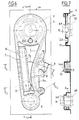
- la Figure 1 est une vue en plan d'une première forme de réalisation de l'empreinte ou emballage de conditionnement selon l'invention, contenant les différentes pièces d'une commande de distribution d'un moteur thermique, vue du côté à présenter sur le moteur :
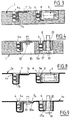
- la Figure 2 est une vue en coupe longitudinale de l'empreinte et des pièces de la Figure 1 suivant l'axe X-X ;
- la Figure 3 est une vue en coupe transversale suivant la ligne Y-Y de la Figure 1 ;
- la Figure 4 est une vue en coupe transversale suivant la ligne Z-Z de la Figure 1 ;
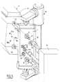
- la Figure 5 est une vue en perspective illustrant l'opération de montage sur l'extrémité d'un moteur thermique, des pièces de la commande de distribution visibles aux Figures 1 à 4 ;
- les Figures 6, 7, 8 et 9 sont des vues analogues respectivement aux Figures 1 à 4 d'une seconde forme de réalisation de l'empreinte selon l'invention.
- On voit aux Figures 1 à 5 une empreinte ou emballage 1, réalisée en une mousse de matière plastique rigide appropriée, telle qu'une mousse de polyéthylène, et qui est adaptée pour recevoir les pièces d'une commande de distribution d'un moteur thermique M (Figure 5) muni d'un arbre à cames 22 et d'un vilebrequin 23.
- L'empreinte 1 comporte des logements agencés pour recevoir les pièces de cette commande, à savoir dans cet exemple : un logement 2a dans lequel peut être placée une roue 2 d'arbre à cames, un logement 3a recevant un pignon 3 de vilebrequin, un logement 5a qui débouche dans les logements 2a, 3a et qui reçoit un élément de transmission du mouvement entre le pignon 3 du vilebrequin 23 et la roue 2 de l'arbre à cames 22, constitué dans cet exemple par une chaîne 4 engrenant dans la roue 2 et sur le pignon 3, cette chaîne 4 s'étendant par conséquent également dans les logements 2a et 3a. Le logement 5a reçoit aussi une lame 6 faisant partie du tendeur 5 et qui vient s'appliquer sur le brin mou de la chaîne 4.
- De son côté, le brin tendu de la chaîne 4 s'étend dans un logement 4a, prolongé latéralement et à sa partie supérieure par un autre logement 7a qui reçoit un guide 7 en forme de cornière, dont une aile s'étend dans le logement 4a et porte une garniture 7b d'appui, en contact avec le brin tendu de la chaîne 4.
- L'empreinte 1 est percée d'une première ouverture ou dégagement 8 d'accès à une vis 10 de fixation de la roue 2 sur l'arbre à cames 22 (représenté en traits mixtes à la Figure 2), une seconde ouverture 9 débouchant dans le logement 3a et qui permet l'accès à une vis 11 de fixation du pignon 3 sur le vilebrequin 23 (en traits mixtes à la Figure 2). Deux autres dégagements 14a, 14b débouchent dans le logement 5a et autorisent l'accès à deux vis 15 de fixation du tendeur 5 sur le moteur M, deux dégagements 16 sont ménagés sous le guide 7 et permettent l'accès deux vis 18 de fixation de ce guide 7 sur le moteur, et enfin une ouverture ou dégagement 17 débouche dans le logement 5a au voisinage du pignon 3, et permet l'accès à une vis 19 d'articulation de la lame 6 autour d'une entretoise 20.
- Les ouvertures 8, 9, 14a, 14b, 16, 17 forment des passages dans l'empreinte 1 et permettent donc l'accès par l'arrière de celle-ci aux vis respectives 10, 11, 15, 18 et 19.
- Un détrompeur, constitué dans cet exemple par un plot 12 de l'empreinte 1, pénètre dans un trou 13 de la roue 2, afin de garantir sans ambiguïté son orientation par rapport au pignon 3.
- L'extrémité du moteur M est percée de trous filetés 15a, 18a, et 19a adaptés pour recevoir respectivement les vis 15, 18, et 19 (Figure 5).
- Tous les logements 2a, 3a, 4a, 5a... précités sont dimensionnés de façon à ce que les pièces correspondantes 2, 3, 4... ne puissent y être reçues qu'en exerçant un léger effort, afin que les parois de ces logements enserrent ces pièces et les maintiennent en place quelle que soit l'orientation de l'empreinte 1 équipée des pièces de cette commande de distribution durant sa manutention avant le montage sur le moteur M. En particulier ce serrage empêche les pièces de tomber en cas de retournement complet de l'empreinte 1.
- Le procédé de montage visé par l'invention, et mis en oeuvre au moyen de l'empreinte 1 qui vient d'être décrite est le suivant.
- Toutes les pièces décrites ci-dessus ayant été prépositionnées et préorientées convenablement dans leurs logements, dans les positions respectives exactes qu'elles doivent occuper sur l'extrémité du moteur M, on présente l'empreinte 1 avec les pièces verticalement devant le moteur M (Figure 5), on engage la roue 2 et le pignon 3 respectivement sur l'arbre à cames 22 et le vilebrequin 23 et on procède à leur fixation au moyen des vis 10, 11. On procède ensuite au vissage des éléments de tension 5 et de guidage 7, en vissant les vis correspondantes 15, 18 et 19 dans leurs trous 15a, 18a, 19a. En variante, la présentation de l'empreinte 1 peut être avantageusement effectuée par un robot 25, et tous les vissages peuvent être avantageusement exécutés de manière simultanée et automatique par une visseuse 24 (Figure 5).
- Enfin, on arrache l'empreinte 1, le montage étant alors terminé.
- L'invention procure des avantages importants pour les fabricants de moteurs :
- l'approvisionnement, la manutention, le stockage et la gestion d'une seule fourniture : l'empreinte équipée de ses pièces ;
- le montage de l'ensemble des pièces de la commande de distribution est réalisé simultanément sur un seul poste, ce qui permet un gain de temps, de personnel et de place considérable ;
- l'opération de montage peut être automatisée grâce à un robot tel que 25 et à une visseuse telle que 24, tous les vissages étant alors simultanés ;
- la mise en oeuvre de l'empreinte ou emballage 1 rend toute erreur de montage impossible, les spécifications de calage relatif entre les diverses pièces étant assurées par l'agencement des logements recevant ces pièces.
- Le second mode de réalisation de l'empreinte conforme à l'invention, illustré aux Figures 6 à 9, diffère du premier en ce que l'empreinte 1 A est ici constituée par une plaque thermoformée. Dans celle-ci, les logements 2a, 3a... des différentes pièces sont identiques à ceux de l'empreinte 1. Par contre, les ouvertures ou dégagements 8A, 9A, 14A, 16A, 17A, correspondant aux dégagements 8, 9, 14... de la première forme de réalisation, sont ici constituées par de simples lumières dans la plaque 1A, par rapport à laquelle font saillie les vis 10, 11, 18... Enfin, au plot 12 de l'empreinte 1 correspond dans cette seconde forme de réalisation un bossage creux 12A de centrage de la roue 2.
- L'invention n'est pas limitée aux formes de réalisations décrites ci-dessus et peut comporter de nombreuses variantes d'exécution, notamment par le fait que divers autres accessoires non représentés, tels qu'une roue de pompe à injection peuvent être prévus dans des logements aménagés à cet effet dans l'empreinte. Enfin, comme déjà indiqué, l'invention est applicable à des domaines autres que l'industrie automobile.
Claims (6)
Applications Claiming Priority (2)
| Application Number | Priority Date | Filing Date | Title |
|---|---|---|---|
| FR8419728A FR2575222B1 (fr) | 1984-12-21 | 1984-12-21 | Procede de montage d'un ensemble de pieces sur un organe support, notamment les pieces d'une commande de distribution d'un moteur thermique, et empreinte de conditionnement pour la mise en oeuvre de ce procede |
| FR8419728 | 1984-12-21 |
Publications (2)
| Publication Number | Publication Date |
|---|---|
| EP0188951A1 EP0188951A1 (fr) | 1986-07-30 |
| EP0188951B1 true EP0188951B1 (fr) | 1989-09-20 |
Family
ID=9310928
Family Applications (1)
| Application Number | Title | Priority Date | Filing Date |
|---|---|---|---|
| EP85402541A Expired EP0188951B1 (fr) | 1984-12-21 | 1985-12-18 | Procédé de montage d'un ensemble de pièces sur un organe support, notamment les pièces d'une commande de distribution d'un moteur thermique, et empreinte de conditionnement pour la mise en oeuvre de ce procédé |
Country Status (5)
| Country | Link |
|---|---|
| US (1) | US4770399A (fr) |
| EP (1) | EP0188951B1 (fr) |
| JP (1) | JPS61152343A (fr) |
| DE (1) | DE3573149D1 (fr) |
| FR (1) | FR2575222B1 (fr) |
Families Citing this family (26)
| Publication number | Priority date | Publication date | Assignee | Title |
|---|---|---|---|---|
| FR2644514A1 (fr) * | 1989-03-15 | 1990-09-21 | Sachs Ind Sa Huret Maillard Re | Sous-ensemble d'entrainement d'elements ou accessoires de moteur thermique et moteur en comportant application |
| FR2647516B1 (fr) * | 1989-05-24 | 1992-10-30 | Peugeot | Dispositif d'accouplement entre un arbre a cames et son pignon de commande |
| FR2656908B1 (fr) * | 1990-01-09 | 1992-05-29 | Peugeot | Dispositif de transmission par lien flexible tel que courroie. |
| IT226611Z2 (it) * | 1992-05-22 | 1997-06-24 | Catene Calibrate Regina Soc It | Gruppo preassemblato di trasmissione a catena e ingranaggi in particolare per il comando di distribuzione in motori a combustione interna |
| US5392524A (en) * | 1993-06-11 | 1995-02-28 | Masco Corporation Of Indiana | Apparatus for aligning handle valves during installation of a faucet |
| US5390422A (en) * | 1993-06-11 | 1995-02-21 | Masco Corporation Of Indiana | Apparatus for aligning handle valves |
| DE4341019A1 (de) * | 1993-12-02 | 1995-06-08 | Ford Werke Ag | Brennkraftmaschine mit Nockenwellen-Kettentrieb-Kassetten |
| DE19503105C1 (de) * | 1995-02-01 | 1996-04-04 | Contitech Antriebssysteme Gmbh | Montageeinheit eines Steuertriebes zur vorpositionierten Montage an einem Verbrennungsmotor |
| DE29611059U1 (de) * | 1996-06-24 | 1997-10-23 | Joh. Winklhofer & Söhne GmbH und Co KG, 81369 München | Montagevorrichtung für einen Zugmittelbetrieb |
| DE29621831U1 (de) * | 1996-12-16 | 1998-04-16 | Joh Winklhofer & Soehne Gmbh U | Vormontierte Zugmitteltriebeinheit |
| JP3894728B2 (ja) * | 2000-12-28 | 2007-03-22 | 本田技研工業株式会社 | エンジンにおける動弁用タイミング伝動装置 |
| DE20120656U1 (de) * | 2001-12-20 | 2003-04-30 | Joh. Winklhofer & Söhne GmbH und Co. KG, 81369 München | Vormontierte Triebmitteleinheit |
| JP4118173B2 (ja) * | 2003-03-18 | 2008-07-16 | 株式会社椿本チエイン | 組立部品保持パネル |
| EP2049816B1 (fr) * | 2006-08-11 | 2011-09-07 | BorgWarner, Inc. | Systeme et procede d'assemblage pour systeme d'entrainement a chaine tendue |
| CN102062183B (zh) * | 2009-11-13 | 2013-06-12 | 中国第一汽车集团公司 | V型发动机链条系统正时装配方法 |
| CN101947728B (zh) * | 2010-08-19 | 2012-11-28 | 奇瑞汽车股份有限公司 | 一种发动机正时链条系统的装配工装及装配方法 |
| CN102011621B (zh) * | 2010-11-29 | 2012-11-14 | 重庆建设摩托车股份有限公司 | 一种摩托车发动机正时传动机构 |
| CN104249320A (zh) * | 2013-06-28 | 2014-12-31 | 北京汽车动力总成有限公司 | 用于发动机正时系统的定位安装系统及定位安装方法 |
| CN104308500B (zh) * | 2014-09-28 | 2016-08-24 | 成都市翻鑫家科技有限公司 | 一种夹具位置可调的多工件定位压装机 |
| CN104339145B (zh) * | 2014-09-28 | 2016-11-16 | 成都市翻鑫家科技有限公司 | 一种具有防错功能的齿轮压装机 |
| CN104191206B (zh) * | 2014-09-28 | 2017-01-18 | 成都市翻鑫家科技有限公司 | 一种夹具位置可调的齿轮防错压装机 |
| EP3369017A4 (fr) * | 2015-10-28 | 2019-06-12 | Sikorsky Aircraft Corporation | Ensemble couvercle de protection et engrenage |
| CN106363389B (zh) * | 2016-11-17 | 2018-07-24 | 张辉 | 电磁阀隔磁组件装配机的卸料装置 |
| DE102018001400A1 (de) * | 2018-02-22 | 2019-08-22 | Borg Warner Inc. | Verfahren zur Montage oder Vorbereitung der Montage eines Zugmittelgetriebemoduls und Zugmittelgetriebemodul |
| CN110253473B (zh) * | 2019-06-20 | 2021-03-23 | 东莞市智赢智能装备有限公司 | 一种动态的带式齿轮机械手夹具 |
| CN110919323B (zh) * | 2019-12-27 | 2024-11-05 | 广西玉柴机器股份有限公司 | 一种曲轴与机体快速定位安装的装置及其装配方法 |
Family Cites Families (10)
| Publication number | Priority date | Publication date | Assignee | Title |
|---|---|---|---|---|
| US1075983A (en) * | 1912-03-07 | 1913-10-14 | Richard Lebenhart | Card for holding articles having an angular profile. |
| US1533588A (en) * | 1924-08-21 | 1925-04-14 | Elmer E Ellis | Tile-mounting device |
| US1904674A (en) * | 1932-02-29 | 1933-04-18 | Arramam B Rlumenthal | Combined graphic outline and work locating template for building models |
| US2353954A (en) * | 1942-06-25 | 1944-07-18 | Beech Aircraft Corp | Jig for assembling components of substructures |
| US2743693A (en) * | 1954-11-22 | 1956-05-01 | Motorola Inc | Transistor assembly jig |
| US3432026A (en) * | 1965-04-07 | 1969-03-11 | Interpace Corp | Place setting packer |
| US3813987A (en) * | 1972-05-10 | 1974-06-04 | Mtm Molded Prod Co | Loading block |
| FR2490594A1 (fr) * | 1980-09-22 | 1982-03-26 | Saint Gobain Emballage | Plateau de positionnement et de maintien d'articles et emballage l'utilisant |
| JPS58217237A (ja) * | 1982-06-14 | 1983-12-17 | Nippon Denso Co Ltd | 製品搬送用汎用治具 |
| FR2545193B1 (fr) * | 1983-04-29 | 1986-10-31 | Sedis Transmissions Mecaniques | Boitier amovible de distribution pour moteur a explosion ou a combustion |
-
1984
- 1984-12-21 FR FR8419728A patent/FR2575222B1/fr not_active Expired
-
1985
- 1985-12-18 EP EP85402541A patent/EP0188951B1/fr not_active Expired
- 1985-12-18 DE DE8585402541T patent/DE3573149D1/de not_active Expired
- 1985-12-19 US US06/811,139 patent/US4770399A/en not_active Expired - Fee Related
- 1985-12-20 JP JP60287641A patent/JPS61152343A/ja active Pending
Also Published As
| Publication number | Publication date |
|---|---|
| JPS61152343A (ja) | 1986-07-11 |
| EP0188951A1 (fr) | 1986-07-30 |
| FR2575222A1 (fr) | 1986-06-27 |
| US4770399A (en) | 1988-09-13 |
| DE3573149D1 (en) | 1989-10-26 |
| FR2575222B1 (fr) | 1987-07-17 |
Similar Documents
| Publication | Publication Date | Title |
|---|---|---|
| EP0188951A1 (fr) | Procédé de montage d'un ensemble de pièces sur un organe support, notamment les pièces d'une commande de distribution d'un moteur thermique, et empreinte de conditionnement pour la mise en oeuvre de ce procédé | |
| EP1241072B1 (fr) | Assemblage d'un étrier de colonne de direction avec un pignon de direction d'un véhicule automobile | |
| FR2589403A1 (fr) | Mecanisme de reglage de phare d'automobile et son boitier | |
| EP3546686A1 (fr) | Dispositif de l'ajustement de l'élévation d'une pièce | |
| EP1460308B1 (fr) | Panneau de positionnement et de retenue d'éléments et méthode de montage et de fixation des éléments | |
| EP0348258B1 (fr) | Système de fixation d'un garnissage et d'un élément tel qu'une poignée sur un panneau de carrosserie | |
| WO2012076330A1 (fr) | Goulotte de reception d'elements allonges, son procede de montage et ensemble comprenant un support et une telle goulotte | |
| FR2574334A1 (fr) | Systeme de manipulation de pieces de montage | |
| FR3061119B1 (fr) | Dispositif d’ecartement a rattrapage angulaire | |
| EP2221494A1 (fr) | Dispositif de fixation d'un palier radial d'un arbre de transmission d'un véhicule | |
| FR3070732B1 (fr) | Systeme de transmission de vehicule automobile comportant un dispositif de maintien de vis de fixation | |
| FR2644514A1 (fr) | Sous-ensemble d'entrainement d'elements ou accessoires de moteur thermique et moteur en comportant application | |
| FR2904785A1 (fr) | Procede de positionnement et de montage dans la culasse d'un moteur de vehicule d'au moins un arbre a cames sur roulements, et dispositif pour la mise en oeuvre d'un tel procede | |
| FR3072072B1 (fr) | Systeme de transmission de vehicule automobile comportant des douilles de maintien de vis de fixation | |
| EP2488404A1 (fr) | Outillage permettant le positionnement manuel et la fixation par vissage d'un sous-ensemble dans une zone peu accessible d'un vehicule | |
| FR2895769A1 (fr) | Dispositif d'assemblage de pieces et procede d'assemblage de pieces utilisant un tel dispositif | |
| EP1637676B1 (fr) | Poignée de portière et procédé pour la monter | |
| FR2871943A1 (fr) | Dispositif de positionnement et de fixation d'un boitier de vehicule automobile, notamment d'une batterie, et procede associe | |
| EP1997664B1 (fr) | Réservoir pour véhicule automobile | |
| JP4228359B2 (ja) | テンショナー | |
| EP0782950A1 (fr) | Volant de direction et colonne adaptée au montage d'un tel volant | |
| EP0570275B1 (fr) | Dispositif de fixation entre deux objets, en particulier entre un support et un tableau de commande | |
| EP1861296A1 (fr) | Dispositif d'entrainement d'un balai d'essuyage, en particulier de vehicule automobile | |
| WO2000039911A1 (fr) | Motoreducteur d'essuyage pour vehicule, a bruit reduit | |
| FR2851200A1 (fr) | Store a boitier incluant des moyens d'assemblage a un support, moyens d'assemblage, ensemble pret a monter, procede de montage et vehicule correspondants |
Legal Events
| Date | Code | Title | Description |
|---|---|---|---|
| PUAI | Public reference made under article 153(3) epc to a published international application that has entered the european phase |
Free format text: ORIGINAL CODE: 0009012 |
|
| AK | Designated contracting states |
Kind code of ref document: A1 Designated state(s): DE GB IT |
|
| 17P | Request for examination filed |
Effective date: 19861227 |
|
| RAP1 | Party data changed (applicant data changed or rights of an application transferred) |
Owner name: SACHS-HURET S.A. Owner name: COMPAGNIE DES TRANSMISSIONS MECANIQUES SEDIS |
|
| 17Q | First examination report despatched |
Effective date: 19871105 |
|
| RAP1 | Party data changed (applicant data changed or rights of an application transferred) |
Owner name: SACHS INDUSTRIES S.A. (HURET ET MAILLARD REUNIS) Owner name: COMPAGNIE DES TRANSMISSIONS MECANIQUES SEDIS SOCIE |
|
| GRAA | (expected) grant |
Free format text: ORIGINAL CODE: 0009210 |
|
| AK | Designated contracting states |
Kind code of ref document: B1 Designated state(s): DE GB IT |
|
| ITF | It: translation for a ep patent filed | ||
| REF | Corresponds to: |
Ref document number: 3573149 Country of ref document: DE Date of ref document: 19891026 |
|
| PGFP | Annual fee paid to national office [announced via postgrant information from national office to epo] |
Ref country code: DE Payment date: 19891113 Year of fee payment: 5 |
|
| ITTA | It: last paid annual fee | ||
| PGFP | Annual fee paid to national office [announced via postgrant information from national office to epo] |
Ref country code: GB Payment date: 19891231 Year of fee payment: 5 |
|
| GBT | Gb: translation of ep patent filed (gb section 77(6)(a)/1977) | ||
| PLBE | No opposition filed within time limit |
Free format text: ORIGINAL CODE: 0009261 |
|
| STAA | Information on the status of an ep patent application or granted ep patent |
Free format text: STATUS: NO OPPOSITION FILED WITHIN TIME LIMIT |
|
| 26N | No opposition filed | ||
| PG25 | Lapsed in a contracting state [announced via postgrant information from national office to epo] |
Ref country code: GB Effective date: 19901218 |
|
| GBPC | Gb: european patent ceased through non-payment of renewal fee | ||
| PG25 | Lapsed in a contracting state [announced via postgrant information from national office to epo] |
Ref country code: DE Effective date: 19910903 |