EP0188706B1 - Appareil de commande du levage ou de l'abaissement de la carrosserie de véhicules à suspension pneumatique - Google Patents
Appareil de commande du levage ou de l'abaissement de la carrosserie de véhicules à suspension pneumatique Download PDFInfo
- Publication number
- EP0188706B1 EP0188706B1 EP85115211A EP85115211A EP0188706B1 EP 0188706 B1 EP0188706 B1 EP 0188706B1 EP 85115211 A EP85115211 A EP 85115211A EP 85115211 A EP85115211 A EP 85115211A EP 0188706 B1 EP0188706 B1 EP 0188706B1
- Authority
- EP
- European Patent Office
- Prior art keywords
- valve
- solenoid valves
- level control
- assigned
- positions
- Prior art date
- Legal status (The legal status is an assumption and is not a legal conclusion. Google has not performed a legal analysis and makes no representation as to the accuracy of the status listed.)
- Expired
Links
Images


Classifications
-
- B—PERFORMING OPERATIONS; TRANSPORTING
- B60—VEHICLES IN GENERAL
- B60G—VEHICLE SUSPENSION ARRANGEMENTS
- B60G17/00—Resilient suspensions having means for adjusting the spring or vibration-damper characteristics, for regulating the distance between a supporting surface and a sprung part of vehicle or for locking suspension during use to meet varying vehicular or surface conditions, e.g. due to speed or load
- B60G17/02—Spring characteristics, e.g. mechanical springs and mechanical adjusting means
- B60G17/04—Spring characteristics, e.g. mechanical springs and mechanical adjusting means fluid spring characteristics
- B60G17/052—Pneumatic spring characteristics
- B60G17/0523—Regulating distributors or valves for pneumatic springs
- B60G17/0525—Height adjusting or levelling valves
-
- B—PERFORMING OPERATIONS; TRANSPORTING
- B60—VEHICLES IN GENERAL
- B60G—VEHICLE SUSPENSION ARRANGEMENTS
- B60G2500/00—Indexing codes relating to the regulated action or device
- B60G2500/20—Spring action or springs
- B60G2500/202—Height or leveling valve for air-springs
-
- B—PERFORMING OPERATIONS; TRANSPORTING
- B60—VEHICLES IN GENERAL
- B60G—VEHICLE SUSPENSION ARRANGEMENTS
- B60G2500/00—Indexing codes relating to the regulated action or device
- B60G2500/20—Spring action or springs
- B60G2500/203—Distributor valve units comprising several elements, e.g. valves, pump or accumulators
-
- Y—GENERAL TAGGING OF NEW TECHNOLOGICAL DEVELOPMENTS; GENERAL TAGGING OF CROSS-SECTIONAL TECHNOLOGIES SPANNING OVER SEVERAL SECTIONS OF THE IPC; TECHNICAL SUBJECTS COVERED BY FORMER USPC CROSS-REFERENCE ART COLLECTIONS [XRACs] AND DIGESTS
- Y10—TECHNICAL SUBJECTS COVERED BY FORMER USPC
- Y10S—TECHNICAL SUBJECTS COVERED BY FORMER USPC CROSS-REFERENCE ART COLLECTIONS [XRACs] AND DIGESTS
- Y10S280/00—Land vehicles
- Y10S280/01—Load responsive, leveling of vehicle
Definitions
- the invention relates to a control system for arbitrarily lifting and lowering the vehicle body of air-sprung vehicles with level control, with a compressed air source, at least one level control valve, at least one air suspension bellows assigned to regulating a desired distance between the vehicle body and the vehicle axle by means of the assigned level control valve with the compressed air source or an unpressurized outlet can be connected and a switching valve built into the line connections of the level control valves with the air bellows or with the compressed air source and the unpressurized outlet with the positions lifting, lowering, travel and stop, the at least one slide valve which can be operated remotely via an electrical switch and two solenoid valves or has a valve construction and releases the line connection in the travel position and interrupts in the other positions and the air bellows in the lifting position with the compressed air source and in the lower position connects to the depressurized outlet.
- the switching valve has only one slide, which can be remotely operated by an electrical switch for the four positions via two solenoid valves, so that it moves from a rest position by a first path when the first solenoid valve is energized, by a second path when the second solenoid valve is energized. is displaceable from the first different path and when both solenoid valves are excited by a third path corresponding to the sum of the first and the second path.
- the line connections and the corresponding seals are arranged and designed in the switching valve and on the slide so that, for example, the driving position is assigned to the non-energized position of the two solenoid valves, while in the stop position, one of the two solenoid valves is energized.
- This assignment of the positions is normal and sensible insofar as the solenoid valves are kept free of current during the journey, which appears much longer in comparison to the other positions. At the same time, this ensures that, in the event of a power failure while driving and the compressed air supply is intact, the air bellows are properly supplied with compressed air via the level control valve or valves.
- German patent application DE-A-3424670 published on January 16, 1986, describes a similar system in which the switching valve has a plurality of individual slides arranged in a common housing, which can be actuated together in the same direction via two pistons which can be controlled via the solenoid valves.
- the position travel is assigned to the non-energized state of the two solenoid valves, for example, so that the normal pressure supply of the air suspension bellows results in the event of a power failure during travel and an intact compressed air supply.
- DE-A-2 645 468 shows a control system with an electrical switch and using two solenoid valves, which, however, are connected upstream of an air spring valve.
- One solenoid valve is arranged in a control line, while the other solenoid valve is provided in the supply line for supplying the air spring valve.
- the setting of the travel position when the solenoid valves are de-energized corresponds to the normal position, because the solenoid valves are thus kept free from permanent load.
- a vehicle must. B. be driven into a hall that has only a limited height, to the underside of which it is necessary to lower the vehicle body into the lower position, and if the electrical supply to the solenoid valves fails, then the drive position is automatically set, so that the vehicle body is raised and thus hits the hall. If, in the event of another damage and the electrical supply is intact while driving, a defect occurs in the compressed air line between the level control valve and the switching valve, the vehicle body can also drop, depending on the circuit. This means that emergency operation can be maintained, but the air suspension system is therefore inoperative.
- the invention has for its object to develop a control system of the type described in such a way that, in the event of pressure and / or electrical failure of the remote control, all the essential pneumatic line connections are shut off from one another, so that when such a defect occurs, the pressure prevailing in the respective operating state in the Air suspension bellows shut off and thus maintained.
- this is achieved in that when the switching valve and / or currentless solenoid valves are depressurized, the slide of the switching valve is designed and is in such a starting position that the pneumatic lines from the switching valve to the level control valve on the one hand and to the air spring valves on the other hand are each shut off, and that the lifting, lowering and travel positions are assigned to the three actuated positions of the two solenoid valves.
- the present invention leaves the normal state of the art and no longer assigns the non-actuated starting position of the two solenoid valves or the slide valve (s) of the switching valve to the travel position, but now to the stop position. By this unusual measure must be accepted that z. B.
- the invention can be used with a very different design of the electrical switching valve.
- This switching valve can have one or more slides or else quite differently, e.g. B. according to valve design. It is also not absolutely necessary for the two pistons to be arranged on one side of the valve and to move in the same direction in order to implement the different paths. An opposite movement and / or a separate arrangement of the pistons at one and at the other end of the slide or slides is quite possible.
- the travel position is assigned to the actuation of only one solenoid valve and the lifting position to the actuation of both solenoid valves, the advantage is achieved that in the travel position which remains switched on for a comparatively long time, only one solenoid valve remains energized continuously.
- the switching valve includes an electrical switch or a button. If a switch is used, it should have a middle position which is assigned to the stop position, the three remaining positions should only be accessible from this middle position or via this middle position. The order of the positions of the switch still says nothing about the order of the positions of the switching valve, but the sequence of operations of the switch ensures an advantageous sequence in that the three active positions of lifting, lowering and travel each follow through the position Stop and can only be stopped by this position stop.
- the arrangement can be such that, for. B. the button assigned to the lift position again sets the stop position after its release.
- the stop position is assigned to the de-energized starting position
- the remaining three active positions of lifting, lowering and driving can be arranged in a total of six different orders, as will be explained with reference to the exemplary embodiments.
- this arrangement is again independent of the design of the switch or the button.
- a time-dependent interrupter to the solenoid valves of the switching valve.
- This interrupter ensures that the solenoid valve or solenoids can only be energized for a limited period of time in one or more of the active positions.
- the interrupter can e.g. B. only be effective if the active position driving is switched on.
- the pressure supply to the air bellows via the level control valve or valves is only carried out for a certain limited period of a few seconds or at most a few minutes, so that it can be assumed that the air suspension bellows are loaded with compressed air in accordance with the loading condition.
- the electrical control line of the solenoid valve (s) in question can be interrupted, so that the stop position is set in which the bellows are blocked and locked with the aid of the switching valve.
- this results in very low air consumption.
- a multi-circuit configuration of the air springs can also be realized in a simple manner, advantageously only one level control valve needing to be used.
- this interrupter it is of course possible to assign this interrupter not only to the travel position, but also to the two other active positions of lifting and lowering, so that there is the further advantage that when a lifting process is triggered, it only lasts for a certain time and thus the vehicle body is only raised by a certain amount. Is this lifting process z. B. not sufficient, the control movement can be carried out a second time.
- An electrical switch 1 permits the setting of the five positions indicated, the stop position being provided twice in each case after the raising or lowering position.
- the driving position can be arranged between the lifting and lowering positions.
- the arrangement can also be made in other ways, such as. B. Fig. 6 reveals.
- Corresponding electrical connection lines 2 lead to a power supply and processing device 3.
- Two electrical lines 4 and 5 lead to a first solenoid valve 6 and to a second solenoid valve 7, which are already arranged on or in the vicinity of a pneumatic switching valve 8, which is on the vehicle body or can be arranged in the vicinity of the axis to be regulated or the air bellows.
- a conventional pneumatic compressed air source not shown, is provided, which feeds a reservoir 9. From there, a pneumatic line 10 leads via a check valve 11 to a connection 12 on the switching valve 8. Further pneumatic lines 13 and 14 lead to level control valves 15 and 16, which are formed in a known manner. Lines 17 and 18 lead to connections 19 and 20 on the pneumatic switching valve. Air bellows 23 and 24 are connected via lines 21 and 22. The air bellows 23 can, for. B. the front axle and the bellows 24 of the rear axle. A division into air suspension bellows provided on the right and left of an axle or other division is also possible.
- the line 13, the level control valve 15, the lines 17 and 22 and the air bellows 24 form an air spring circuit. The same applies to the second air spring circuit shown.
- the pneumatic switching valve 8 can also be designed in a simple manner for a third or a fourth air spring circuit. It is also possible to provide only one level control valve instead of the two level control valves 15 and 16, so that the dual circuit of the two air spring circuits then only begins at the switching valve 8.
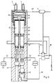
- the switching valve 8 has a housing 25 in which a plurality of individual slides 26, 26 'are slidably mounted.
- the individual slides 26 and 26 ' have circumferential seals 27, 28, 29, 30, 31, which are provided in relation to the housing configuration, as shown, and to the connections 19, 20 and further connections 33 and 34 for the air bellows 23 and 24, respectively are.
- two bores 32 and 32 ' which are designed in a stepped manner, are provided in which the individual slides 26 and 26' are guided in a sliding and sealing manner.
- a circumferential groove 35 interrupted by the seal 28 is provided, through which in connection with the correspondingly offset bores 32 and 32' of the connection 20 with the connection 33 on the one hand and Port 19 is connected to port 34 on the other hand in the travel position (Fig. 2). 1, which corresponds to the stop position, the two solenoid valves 6 and 7 are not energized and both the connections 19 and 20 to the level control valves 15 and 16 and the connections 33 and 34 to the Air bags 23 and 24 are locked.
- a further circumferential groove 36 can be provided between the seals 30 and 31 or 29 and 31.
- a connecting channel 37 leads to an outlet space 38 and, on the other hand, to an inlet valve 39, 40 comprising a valve body 40 and a housing edge 39. Compressed air is present via the inlet 12 via an inlet chamber 41. Below the individual slides 26 and 26 'a pressure chamber 42 is provided, from which the inlet valve 39, 40 and on the other hand the outlet valve 27, 44 can be reached via the connecting channel 37, which is formed by the seal 27 and an edge 44 on the housing 25.
- the valve body 40 is supported on a spring 43 on the housing side.
- a vent hole 45 leads from the outlet space 38 into the atmosphere.
- Single slide 26 ' has an extension 60 for actuating the inlet valve 39, 40.
- the switching piston 46 can carry out a first piston stroke into the lowering position (FIG. 3) when it is only supplied with compressed air, which is done by energizing the solenoid valve 6.
- the switching piston 47 can cover a comparatively smaller piston stroke in the travel position (FIG. 2), which is done by energizing the solenoid valve 7 alone. All the individual slides 26 and 26 'rest on the switching piston 47 and, via this, on the switching piston 46.
- a line 54 leads from the solenoid valve 7 to the active surface 55 of the switching piston 47.
- the geometric conditions of the various strokes of the switching piston 46 and 47 and the spacing of the seals 27 to 31 from each other as well as the diameter design of the individual slides 26 and 26 'and the stepped bores 33 and 32' are correspondingly coordinated with one another. This coordination can be done in various ways per se, ie there are several options for distributing the four positions stop, travel, lowering, lifting and assigning them to the individual positions of the switching pistons 46 and 47. The basic options are shown in the table below:
- FIGS. 1 to 4 represents the first of the six possibilities (columns) or corresponds to such a distribution.
- Fig. 1 shows the stop position
- Fig. 2 the travel position
- Fig. 3 the lower position
- Fig. 4 the lifting position
- 5 shows, for example, an arrangement in which the sequence according to column 2 is realized.
- the lines 17 and 18 are blocked by the level control valves 15 and 16 through the seals 28 and 29.
- the lines 21 and 22 to the air bellows 23 and 24 are blocked by the seals 27 and 28.
- the inlet valve 39, 40 is closed.
- the outlet valve 27, 44 is open.
- the solenoid valves 6 and 7 are not energized, so that the active surfaces 53 and 55 of the switching pistons 46 and 47 are vented via the vent openings 50 and 51, i. H. are connected to the atmosphere.
- the return spring 48 holds the switching pistons 46 and 47 in their starting position.
- the non-energized position of the solenoid valves 6 and 7 is always set when one of the two positions Stop is set on the switch 1. The same relative position of the parts also results when the power supply fails, so that the solenoid valves 6 and 7 become de-energized.
- the switch 1 is pivoted into the lower position, then only the solenoid valve 6, but not the solenoid valve 7, is excited, so that there is a relative position of the parts, as can be seen in FIG. 3.
- the switching piston 46 travels a comparatively larger distance and takes the switching piston 47 with it, which in turn is not acted upon by compressed air on its active surface 55.
- the lines 17 and 18 to the level control valves 15 and 16 are thus blocked by the seals 29 and 31.
- the seals 27 are released from their sealing position by driving into the expanded pressure chamber 42, so that the lines 21 and 22 are connected to the atmosphere via the vent hole 45.
- the compressed air can escape from the air bellows 23 and 24 as a function of time, so that the vehicle body is lowered.
- the embodiment according to FIG. 5 has a very similar structure.
- the supply line 49 leading upward from the connection 12 is missing, which instead is led directly from the storage container 9 in a direct way.
- Only one level control valve 15 is provided, the two control lines 17 and 18 of which are connected in the manner shown.
- the level control valve 15 is supplied with supply air via line 13.
- the line 10 leads compressed air via a locking device on the level control valve 15 to the connection 12.
- the geometry of the individual slides 26 and 26 'and the stepped bores 32 and 32' is designed somewhat differently here, so that in the sense of increasing strokes a switching sequence stop , Lowering, driving and lifting results.
- the function is otherwise analogous to that of the exemplary embodiment in FIGS. 1 to 4.
- the control system shown in FIG. 6 is in turn similar in structure and function, with identical reference numerals being given for comparable parts.
- the switch 1 is designed here so that either the lowering, lifting and driving positions can be reached from a central position, which is assigned to the stop position, while it is only possible to switch from an active position to another active position in that the stop position is passed through.
- two level control valves 15 and 16 are again provided, it being understood that, of course, only one level control valve could be used. Only a single slide valve 26 is provided here, but which now receives all of the seals 27, 28, 29, 29a, 30, 31, 31 a, which are provided in the relative position shown.
Landscapes
- Engineering & Computer Science (AREA)
- Mechanical Engineering (AREA)
- Vehicle Body Suspensions (AREA)
Claims (4)
Applications Claiming Priority (2)
| Application Number | Priority Date | Filing Date | Title |
|---|---|---|---|
| DE3445579 | 1984-12-14 | ||
| DE3445579A DE3445579C1 (de) | 1984-12-14 | 1984-12-14 | Steueranlage zum Heben und Senken des Fahrzeugaufbaus von luftgefederten Fahrzeugen |
Publications (2)
| Publication Number | Publication Date |
|---|---|
| EP0188706A1 EP0188706A1 (fr) | 1986-07-30 |
| EP0188706B1 true EP0188706B1 (fr) | 1988-08-17 |
Family
ID=6252737
Family Applications (1)
| Application Number | Title | Priority Date | Filing Date |
|---|---|---|---|
| EP85115211A Expired EP0188706B1 (fr) | 1984-12-14 | 1985-11-30 | Appareil de commande du levage ou de l'abaissement de la carrosserie de véhicules à suspension pneumatique |
Country Status (3)
| Country | Link |
|---|---|
| US (1) | US4697822A (fr) |
| EP (1) | EP0188706B1 (fr) |
| DE (1) | DE3445579C1 (fr) |
Families Citing this family (18)
| Publication number | Priority date | Publication date | Assignee | Title |
|---|---|---|---|---|
| JP2537226B2 (ja) * | 1987-03-06 | 1996-09-25 | 日産自動車株式会社 | 能動型サスペンシヨン装置 |
| DE3731279A1 (de) * | 1987-09-17 | 1989-04-06 | Teves Gmbh Alfred | Niveauregelanlage fuer kraftfahrzeuge |
| DE3742021C1 (en) * | 1987-12-11 | 1989-04-13 | Graubremse Gmbh | Pneumatic switching valve for pistons for raising and lowering the vehicle body of air-suspended vehicles |
| GB2213782A (en) * | 1987-12-17 | 1989-08-23 | Automotive Products Plc | A controlled vehicle suspension system |
| DE3825408A1 (de) * | 1988-07-27 | 1990-02-01 | Man Nutzfahrzeuge Ag | Vorrichtung zum zu- und abschalten der mittragfunktion einer mitlauf- oder liftachse |
| DE3915826C1 (fr) * | 1989-05-16 | 1990-06-28 | Graubremse Gmbh, 6900 Heidelberg, De | |
| DE4012251C1 (fr) * | 1990-04-14 | 1991-07-11 | Grau Gmbh, 6900 Heidelberg, De | |
| GB9305552D0 (en) * | 1993-03-18 | 1993-05-05 | Keymed Medicals & Ind Equip | Adjustable load supporting apparatus |
| DE4327764C2 (de) * | 1993-08-18 | 2002-08-14 | Knorr Bremse Systeme | Luftfederungsanlage |
| US5560591A (en) * | 1995-05-02 | 1996-10-01 | Hadley Products | Leveling valve for air springs |
| DE102006017890C5 (de) | 2005-04-16 | 2015-11-19 | Haldex Brake Products Gmbh | Schaltventil für Anlagen zum Heben und Senken eines Fahrzeugaufbaus |
| DE102006006439B4 (de) † | 2006-02-13 | 2008-11-27 | Wabco Gmbh | Ventileinrichtung zur manuellen Veränderung der Niveaulage eines luftgefederten Fahrzeuges |
| DE102008039754B4 (de) | 2008-08-26 | 2014-01-16 | Haldex Brake Products Gmbh | Anlage zum Heben und Senken eines Fahrzeugaufbaus |
| DE102009005229C5 (de) * | 2009-01-20 | 2019-09-12 | Haldex Brake Products Aktiebolag | Luftfederanlage mit Höhenbegrenzung |
| CA2700149A1 (fr) * | 2009-04-15 | 2010-10-15 | Dallas Smith Corp. | Methode et appareil de conversion de suspension |
| US9101519B2 (en) | 2013-02-07 | 2015-08-11 | Dallas Smith Corporation | Leveling ramp for a wheelchair |
| US8973922B2 (en) * | 2013-03-15 | 2015-03-10 | Haldex Brake Products Corporation | Air suspension height control valve with dual ride height positions |
| US9653243B2 (en) * | 2013-10-25 | 2017-05-16 | Siemens Aktiengesellschaft | Separating unit with electromagnetic drive |
Family Cites Families (9)
| Publication number | Priority date | Publication date | Assignee | Title |
|---|---|---|---|---|
| US3836161A (en) * | 1973-01-08 | 1974-09-17 | Midland Ross Corp | Leveling system for vehicles with optional manual or automatic control |
| GB1456873A (en) * | 1973-06-30 | 1976-12-01 | Nissan Motor | Vehicle having a fluid operated vehicle body level control system |
| US3917307A (en) * | 1974-06-03 | 1975-11-04 | Ati Ind | Vehicle leveling and stabilizing system |
| DE2645468A1 (de) * | 1976-10-08 | 1978-04-13 | Maschf Augsburg Nuernberg Ag | Elektrisch pneumatische hebe- und senkvorrichtung fuer einen fahrzeugaufbau |
| CA1102829A (fr) * | 1978-07-27 | 1981-06-09 | Herbert E. Gladish | Traduction non-disponible |
| DE2942081A1 (de) * | 1979-10-18 | 1981-05-14 | Wabco Fahrzeugbremsen Gmbh, 3000 Hannover | Pneumatische hebe- und senkanlage fuer kraftfahrzeugaufbauten |
| DE3300662A1 (de) * | 1983-01-11 | 1984-07-12 | Mannesmann Rexroth GmbH, 8770 Lohr | Niveauregeleinrichtung fuer fahrzeuge |
| DE3424670A1 (de) * | 1983-12-06 | 1986-01-16 | Graubremse Gmbh, 6900 Heidelberg | Anlage zum heben und senken des fahrzeugaufbaus von luftgefederten fahrzeugen |
| DE3344022C1 (de) * | 1983-12-06 | 1989-11-23 | Graubremse Gmbh, 6900 Heidelberg | Anlage zum Heben und Senken des Fahrzeugaufbaus von luftgefederten Fahrzeugen |
-
1984
- 1984-12-14 DE DE3445579A patent/DE3445579C1/de not_active Expired
-
1985
- 1985-11-30 EP EP85115211A patent/EP0188706B1/fr not_active Expired
- 1985-12-13 US US06/808,857 patent/US4697822A/en not_active Expired - Fee Related
Also Published As
| Publication number | Publication date |
|---|---|
| US4697822A (en) | 1987-10-06 |
| EP0188706A1 (fr) | 1986-07-30 |
| DE3445579C1 (de) | 1986-06-12 |
Similar Documents
| Publication | Publication Date | Title |
|---|---|---|
| EP0188706B1 (fr) | Appareil de commande du levage ou de l'abaissement de la carrosserie de véhicules à suspension pneumatique | |
| DE19530260C2 (de) | Luftfederungsanlage für Fahrzeuge | |
| EP1741578B1 (fr) | Dispositif de commande de système de suspension pneumatique d'un véhicule | |
| DE3344022C1 (de) | Anlage zum Heben und Senken des Fahrzeugaufbaus von luftgefederten Fahrzeugen | |
| DE3530657C2 (de) | Vorrichtung zum Ansteuern hydraulischer, im untertägigen Bergbau eingesetzter Verbraucher | |
| DE10338162B3 (de) | Verfahren zum Betreiben einer Druckluftbeschaffungsanlage eines Kraftfahrzeuges sowie Druckluftaufbereitungseinrichtung | |
| DE4327764A1 (de) | Luftfederungsanlage | |
| DE19649498C1 (de) | Druckluftaufbereitungseinrichtung für Druckluftbeschaffungsanlagen auf Kraftfahrzeugen | |
| DD144590A5 (de) | Doppel-sicherheitsventil | |
| EP0464375A1 (fr) | Système de freinage hydraulique | |
| EP0277602A2 (fr) | Système hydraulique de commande pour vérins de travail dans des véhicules | |
| DE2810219C2 (fr) | ||
| EP2177381B1 (fr) | Ensemble de clapets pour un système de suspension pneumatique | |
| DE4016308A1 (de) | Hydraulische zweikreisbremsanlage | |
| EP0307576B1 (fr) | Valve relais | |
| DE3424670C2 (fr) | ||
| DE3809338C1 (en) | Control valve with relay action for motor vehicles or trailers | |
| EP0398009B1 (fr) | Soupape de commutation pouvant être reliée à une soupape de régulation de niveau par un branchement de fluide de commande ou commandée électriquement | |
| DE10220790C1 (de) | Druckluftaufbereitungseinrichtung für Kfz-Druckluftanlagen | |
| DE19905113B4 (de) | Liftachsventil zum Steuern der Liftachsfunktionen eines Fahrzeugs mit mehreren Hinterachsen | |
| DE10220791A1 (de) | Druckluftverteilungseinrichtung für Kfz-Druckluftanlagen | |
| DE3742021C1 (en) | Pneumatic switching valve for pistons for raising and lowering the vehicle body of air-suspended vehicles | |
| DE718414C (de) | Einrichtung zum Steuern von Bremsen, insbesondere fuer Eisenbahnen und Kraftwagen | |
| DE3643501C2 (de) | Blockschaltung für mehrere elektromagnetisch gesteuerte Hydraulikventile | |
| DE2541416C3 (de) | Führerbremsventileinrichtung, insbesondere von Schienenfahrzeugen |
Legal Events
| Date | Code | Title | Description |
|---|---|---|---|
| PUAI | Public reference made under article 153(3) epc to a published international application that has entered the european phase |
Free format text: ORIGINAL CODE: 0009012 |
|
| AK | Designated contracting states |
Kind code of ref document: A1 Designated state(s): FR GB IT |
|
| 17P | Request for examination filed |
Effective date: 19860825 |
|
| 17Q | First examination report despatched |
Effective date: 19871204 |
|
| ITF | It: translation for a ep patent filed |
Owner name: DE DOMINICIS & MAYER S.R.L. |
|
| GRAA | (expected) grant |
Free format text: ORIGINAL CODE: 0009210 |
|
| AK | Designated contracting states |
Kind code of ref document: B1 Designated state(s): FR GB IT |
|
| GBT | Gb: translation of ep patent filed (gb section 77(6)(a)/1977) | ||
| ET | Fr: translation filed | ||
| PLBE | No opposition filed within time limit |
Free format text: ORIGINAL CODE: 0009261 |
|
| STAA | Information on the status of an ep patent application or granted ep patent |
Free format text: STATUS: NO OPPOSITION FILED WITHIN TIME LIMIT |
|
| 26N | No opposition filed | ||
| ITTA | It: last paid annual fee | ||
| PGFP | Annual fee paid to national office [announced via postgrant information from national office to epo] |
Ref country code: FR Payment date: 19921116 Year of fee payment: 8 |
|
| PGFP | Annual fee paid to national office [announced via postgrant information from national office to epo] |
Ref country code: GB Payment date: 19921118 Year of fee payment: 8 |
|
| PG25 | Lapsed in a contracting state [announced via postgrant information from national office to epo] |
Ref country code: GB Effective date: 19931130 |
|
| GBPC | Gb: european patent ceased through non-payment of renewal fee |
Effective date: 19931130 |
|
| PG25 | Lapsed in a contracting state [announced via postgrant information from national office to epo] |
Ref country code: FR Effective date: 19940729 |
|
| REG | Reference to a national code |
Ref country code: FR Ref legal event code: ST |