EP0188706B1 - Control device for raising and lowering the body of vehicles with pneumatic suspension - Google Patents
Control device for raising and lowering the body of vehicles with pneumatic suspension Download PDFInfo
- Publication number
- EP0188706B1 EP0188706B1 EP85115211A EP85115211A EP0188706B1 EP 0188706 B1 EP0188706 B1 EP 0188706B1 EP 85115211 A EP85115211 A EP 85115211A EP 85115211 A EP85115211 A EP 85115211A EP 0188706 B1 EP0188706 B1 EP 0188706B1
- Authority
- EP
- European Patent Office
- Prior art keywords
- valve
- solenoid valves
- level control
- assigned
- positions
- Prior art date
- Legal status (The legal status is an assumption and is not a legal conclusion. Google has not performed a legal analysis and makes no representation as to the accuracy of the status listed.)
- Expired
Links
Images


Classifications
-
- B—PERFORMING OPERATIONS; TRANSPORTING
- B60—VEHICLES IN GENERAL
- B60G—VEHICLE SUSPENSION ARRANGEMENTS
- B60G17/00—Resilient suspensions having means for adjusting the spring or vibration-damper characteristics, for regulating the distance between a supporting surface and a sprung part of vehicle or for locking suspension during use to meet varying vehicular or surface conditions, e.g. due to speed or load
- B60G17/02—Spring characteristics, e.g. mechanical springs and mechanical adjusting means
- B60G17/04—Spring characteristics, e.g. mechanical springs and mechanical adjusting means fluid spring characteristics
- B60G17/052—Pneumatic spring characteristics
- B60G17/0523—Regulating distributors or valves for pneumatic springs
- B60G17/0525—Height adjusting or levelling valves
-
- B—PERFORMING OPERATIONS; TRANSPORTING
- B60—VEHICLES IN GENERAL
- B60G—VEHICLE SUSPENSION ARRANGEMENTS
- B60G2500/00—Indexing codes relating to the regulated action or device
- B60G2500/20—Spring action or springs
- B60G2500/202—Height or leveling valve for air-springs
-
- B—PERFORMING OPERATIONS; TRANSPORTING
- B60—VEHICLES IN GENERAL
- B60G—VEHICLE SUSPENSION ARRANGEMENTS
- B60G2500/00—Indexing codes relating to the regulated action or device
- B60G2500/20—Spring action or springs
- B60G2500/203—Distributor valve units comprising several elements, e.g. valves, pump or accumulators
-
- Y—GENERAL TAGGING OF NEW TECHNOLOGICAL DEVELOPMENTS; GENERAL TAGGING OF CROSS-SECTIONAL TECHNOLOGIES SPANNING OVER SEVERAL SECTIONS OF THE IPC; TECHNICAL SUBJECTS COVERED BY FORMER USPC CROSS-REFERENCE ART COLLECTIONS [XRACs] AND DIGESTS
- Y10—TECHNICAL SUBJECTS COVERED BY FORMER USPC
- Y10S—TECHNICAL SUBJECTS COVERED BY FORMER USPC CROSS-REFERENCE ART COLLECTIONS [XRACs] AND DIGESTS
- Y10S280/00—Land vehicles
- Y10S280/01—Load responsive, leveling of vehicle
Definitions
- the invention relates to a control system for arbitrarily lifting and lowering the vehicle body of air-sprung vehicles with level control, with a compressed air source, at least one level control valve, at least one air suspension bellows assigned to regulating a desired distance between the vehicle body and the vehicle axle by means of the assigned level control valve with the compressed air source or an unpressurized outlet can be connected and a switching valve built into the line connections of the level control valves with the air bellows or with the compressed air source and the unpressurized outlet with the positions lifting, lowering, travel and stop, the at least one slide valve which can be operated remotely via an electrical switch and two solenoid valves or has a valve construction and releases the line connection in the travel position and interrupts in the other positions and the air bellows in the lifting position with the compressed air source and in the lower position connects to the depressurized outlet.
- the switching valve has only one slide, which can be remotely operated by an electrical switch for the four positions via two solenoid valves, so that it moves from a rest position by a first path when the first solenoid valve is energized, by a second path when the second solenoid valve is energized. is displaceable from the first different path and when both solenoid valves are excited by a third path corresponding to the sum of the first and the second path.
- the line connections and the corresponding seals are arranged and designed in the switching valve and on the slide so that, for example, the driving position is assigned to the non-energized position of the two solenoid valves, while in the stop position, one of the two solenoid valves is energized.
- This assignment of the positions is normal and sensible insofar as the solenoid valves are kept free of current during the journey, which appears much longer in comparison to the other positions. At the same time, this ensures that, in the event of a power failure while driving and the compressed air supply is intact, the air bellows are properly supplied with compressed air via the level control valve or valves.
- German patent application DE-A-3424670 published on January 16, 1986, describes a similar system in which the switching valve has a plurality of individual slides arranged in a common housing, which can be actuated together in the same direction via two pistons which can be controlled via the solenoid valves.
- the position travel is assigned to the non-energized state of the two solenoid valves, for example, so that the normal pressure supply of the air suspension bellows results in the event of a power failure during travel and an intact compressed air supply.
- DE-A-2 645 468 shows a control system with an electrical switch and using two solenoid valves, which, however, are connected upstream of an air spring valve.
- One solenoid valve is arranged in a control line, while the other solenoid valve is provided in the supply line for supplying the air spring valve.
- the setting of the travel position when the solenoid valves are de-energized corresponds to the normal position, because the solenoid valves are thus kept free from permanent load.
- a vehicle must. B. be driven into a hall that has only a limited height, to the underside of which it is necessary to lower the vehicle body into the lower position, and if the electrical supply to the solenoid valves fails, then the drive position is automatically set, so that the vehicle body is raised and thus hits the hall. If, in the event of another damage and the electrical supply is intact while driving, a defect occurs in the compressed air line between the level control valve and the switching valve, the vehicle body can also drop, depending on the circuit. This means that emergency operation can be maintained, but the air suspension system is therefore inoperative.
- the invention has for its object to develop a control system of the type described in such a way that, in the event of pressure and / or electrical failure of the remote control, all the essential pneumatic line connections are shut off from one another, so that when such a defect occurs, the pressure prevailing in the respective operating state in the Air suspension bellows shut off and thus maintained.
- this is achieved in that when the switching valve and / or currentless solenoid valves are depressurized, the slide of the switching valve is designed and is in such a starting position that the pneumatic lines from the switching valve to the level control valve on the one hand and to the air spring valves on the other hand are each shut off, and that the lifting, lowering and travel positions are assigned to the three actuated positions of the two solenoid valves.
- the present invention leaves the normal state of the art and no longer assigns the non-actuated starting position of the two solenoid valves or the slide valve (s) of the switching valve to the travel position, but now to the stop position. By this unusual measure must be accepted that z. B.
- the invention can be used with a very different design of the electrical switching valve.
- This switching valve can have one or more slides or else quite differently, e.g. B. according to valve design. It is also not absolutely necessary for the two pistons to be arranged on one side of the valve and to move in the same direction in order to implement the different paths. An opposite movement and / or a separate arrangement of the pistons at one and at the other end of the slide or slides is quite possible.
- the travel position is assigned to the actuation of only one solenoid valve and the lifting position to the actuation of both solenoid valves, the advantage is achieved that in the travel position which remains switched on for a comparatively long time, only one solenoid valve remains energized continuously.
- the switching valve includes an electrical switch or a button. If a switch is used, it should have a middle position which is assigned to the stop position, the three remaining positions should only be accessible from this middle position or via this middle position. The order of the positions of the switch still says nothing about the order of the positions of the switching valve, but the sequence of operations of the switch ensures an advantageous sequence in that the three active positions of lifting, lowering and travel each follow through the position Stop and can only be stopped by this position stop.
- the arrangement can be such that, for. B. the button assigned to the lift position again sets the stop position after its release.
- the stop position is assigned to the de-energized starting position
- the remaining three active positions of lifting, lowering and driving can be arranged in a total of six different orders, as will be explained with reference to the exemplary embodiments.
- this arrangement is again independent of the design of the switch or the button.
- a time-dependent interrupter to the solenoid valves of the switching valve.
- This interrupter ensures that the solenoid valve or solenoids can only be energized for a limited period of time in one or more of the active positions.
- the interrupter can e.g. B. only be effective if the active position driving is switched on.
- the pressure supply to the air bellows via the level control valve or valves is only carried out for a certain limited period of a few seconds or at most a few minutes, so that it can be assumed that the air suspension bellows are loaded with compressed air in accordance with the loading condition.
- the electrical control line of the solenoid valve (s) in question can be interrupted, so that the stop position is set in which the bellows are blocked and locked with the aid of the switching valve.
- this results in very low air consumption.
- a multi-circuit configuration of the air springs can also be realized in a simple manner, advantageously only one level control valve needing to be used.
- this interrupter it is of course possible to assign this interrupter not only to the travel position, but also to the two other active positions of lifting and lowering, so that there is the further advantage that when a lifting process is triggered, it only lasts for a certain time and thus the vehicle body is only raised by a certain amount. Is this lifting process z. B. not sufficient, the control movement can be carried out a second time.
- An electrical switch 1 permits the setting of the five positions indicated, the stop position being provided twice in each case after the raising or lowering position.
- the driving position can be arranged between the lifting and lowering positions.
- the arrangement can also be made in other ways, such as. B. Fig. 6 reveals.
- Corresponding electrical connection lines 2 lead to a power supply and processing device 3.
- Two electrical lines 4 and 5 lead to a first solenoid valve 6 and to a second solenoid valve 7, which are already arranged on or in the vicinity of a pneumatic switching valve 8, which is on the vehicle body or can be arranged in the vicinity of the axis to be regulated or the air bellows.
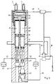
- a conventional pneumatic compressed air source not shown, is provided, which feeds a reservoir 9. From there, a pneumatic line 10 leads via a check valve 11 to a connection 12 on the switching valve 8. Further pneumatic lines 13 and 14 lead to level control valves 15 and 16, which are formed in a known manner. Lines 17 and 18 lead to connections 19 and 20 on the pneumatic switching valve. Air bellows 23 and 24 are connected via lines 21 and 22. The air bellows 23 can, for. B. the front axle and the bellows 24 of the rear axle. A division into air suspension bellows provided on the right and left of an axle or other division is also possible.
- the line 13, the level control valve 15, the lines 17 and 22 and the air bellows 24 form an air spring circuit. The same applies to the second air spring circuit shown.
- the pneumatic switching valve 8 can also be designed in a simple manner for a third or a fourth air spring circuit. It is also possible to provide only one level control valve instead of the two level control valves 15 and 16, so that the dual circuit of the two air spring circuits then only begins at the switching valve 8.
- the switching valve 8 has a housing 25 in which a plurality of individual slides 26, 26 'are slidably mounted.
- the individual slides 26 and 26 ' have circumferential seals 27, 28, 29, 30, 31, which are provided in relation to the housing configuration, as shown, and to the connections 19, 20 and further connections 33 and 34 for the air bellows 23 and 24, respectively are.
- two bores 32 and 32 ' which are designed in a stepped manner, are provided in which the individual slides 26 and 26' are guided in a sliding and sealing manner.
- a circumferential groove 35 interrupted by the seal 28 is provided, through which in connection with the correspondingly offset bores 32 and 32' of the connection 20 with the connection 33 on the one hand and Port 19 is connected to port 34 on the other hand in the travel position (Fig. 2). 1, which corresponds to the stop position, the two solenoid valves 6 and 7 are not energized and both the connections 19 and 20 to the level control valves 15 and 16 and the connections 33 and 34 to the Air bags 23 and 24 are locked.
- a further circumferential groove 36 can be provided between the seals 30 and 31 or 29 and 31.
- a connecting channel 37 leads to an outlet space 38 and, on the other hand, to an inlet valve 39, 40 comprising a valve body 40 and a housing edge 39. Compressed air is present via the inlet 12 via an inlet chamber 41. Below the individual slides 26 and 26 'a pressure chamber 42 is provided, from which the inlet valve 39, 40 and on the other hand the outlet valve 27, 44 can be reached via the connecting channel 37, which is formed by the seal 27 and an edge 44 on the housing 25.
- the valve body 40 is supported on a spring 43 on the housing side.
- a vent hole 45 leads from the outlet space 38 into the atmosphere.
- Single slide 26 ' has an extension 60 for actuating the inlet valve 39, 40.
- the switching piston 46 can carry out a first piston stroke into the lowering position (FIG. 3) when it is only supplied with compressed air, which is done by energizing the solenoid valve 6.
- the switching piston 47 can cover a comparatively smaller piston stroke in the travel position (FIG. 2), which is done by energizing the solenoid valve 7 alone. All the individual slides 26 and 26 'rest on the switching piston 47 and, via this, on the switching piston 46.
- a line 54 leads from the solenoid valve 7 to the active surface 55 of the switching piston 47.
- the geometric conditions of the various strokes of the switching piston 46 and 47 and the spacing of the seals 27 to 31 from each other as well as the diameter design of the individual slides 26 and 26 'and the stepped bores 33 and 32' are correspondingly coordinated with one another. This coordination can be done in various ways per se, ie there are several options for distributing the four positions stop, travel, lowering, lifting and assigning them to the individual positions of the switching pistons 46 and 47. The basic options are shown in the table below:
- FIGS. 1 to 4 represents the first of the six possibilities (columns) or corresponds to such a distribution.
- Fig. 1 shows the stop position
- Fig. 2 the travel position
- Fig. 3 the lower position
- Fig. 4 the lifting position
- 5 shows, for example, an arrangement in which the sequence according to column 2 is realized.
- the lines 17 and 18 are blocked by the level control valves 15 and 16 through the seals 28 and 29.
- the lines 21 and 22 to the air bellows 23 and 24 are blocked by the seals 27 and 28.
- the inlet valve 39, 40 is closed.
- the outlet valve 27, 44 is open.
- the solenoid valves 6 and 7 are not energized, so that the active surfaces 53 and 55 of the switching pistons 46 and 47 are vented via the vent openings 50 and 51, i. H. are connected to the atmosphere.
- the return spring 48 holds the switching pistons 46 and 47 in their starting position.
- the non-energized position of the solenoid valves 6 and 7 is always set when one of the two positions Stop is set on the switch 1. The same relative position of the parts also results when the power supply fails, so that the solenoid valves 6 and 7 become de-energized.
- the switch 1 is pivoted into the lower position, then only the solenoid valve 6, but not the solenoid valve 7, is excited, so that there is a relative position of the parts, as can be seen in FIG. 3.
- the switching piston 46 travels a comparatively larger distance and takes the switching piston 47 with it, which in turn is not acted upon by compressed air on its active surface 55.
- the lines 17 and 18 to the level control valves 15 and 16 are thus blocked by the seals 29 and 31.
- the seals 27 are released from their sealing position by driving into the expanded pressure chamber 42, so that the lines 21 and 22 are connected to the atmosphere via the vent hole 45.
- the compressed air can escape from the air bellows 23 and 24 as a function of time, so that the vehicle body is lowered.
- the embodiment according to FIG. 5 has a very similar structure.
- the supply line 49 leading upward from the connection 12 is missing, which instead is led directly from the storage container 9 in a direct way.
- Only one level control valve 15 is provided, the two control lines 17 and 18 of which are connected in the manner shown.
- the level control valve 15 is supplied with supply air via line 13.
- the line 10 leads compressed air via a locking device on the level control valve 15 to the connection 12.
- the geometry of the individual slides 26 and 26 'and the stepped bores 32 and 32' is designed somewhat differently here, so that in the sense of increasing strokes a switching sequence stop , Lowering, driving and lifting results.
- the function is otherwise analogous to that of the exemplary embodiment in FIGS. 1 to 4.
- the control system shown in FIG. 6 is in turn similar in structure and function, with identical reference numerals being given for comparable parts.
- the switch 1 is designed here so that either the lowering, lifting and driving positions can be reached from a central position, which is assigned to the stop position, while it is only possible to switch from an active position to another active position in that the stop position is passed through.
- two level control valves 15 and 16 are again provided, it being understood that, of course, only one level control valve could be used. Only a single slide valve 26 is provided here, but which now receives all of the seals 27, 28, 29, 29a, 30, 31, 31 a, which are provided in the relative position shown.
Description
Die Erfindung bezieht sich auf eine Steueranlage zum willkürlichen Heben und Senken des Fahrzeugaufbaus von luftgefederten Fahrzeugen mit Niveauregelung, mit einer Druckluftquelle, mindestens einem Niveauregelventil, mindestens einer Fahrzeugachse zugeordneten Luftfederbälgen, die zur Einregelung eines Sollabstands zwischen Fahrzeugaufbau und Fahrzeugachse durch das zugeordnete Niveauregelventil mit der Druckluftquelle oder einem drucklosen Auslaß verbindbar sind und einem in die Leitungsverbindungen der Niveauregelventile mit den Luftfederbälgen oder mit der Druckluftquelle und dem drucklosen Auslaß eingebauten Schaltventil mit den Stellungen Heben, Senken, Fahrt und Stop, das mindestens einen über einen elektrischen Schalter und zwei Magnetventile fernbetätigbaren Schieber oder eine Ventilkonstruktion aufweist und die Leitungsverbindung in der Stellung Fahrt freigibt und in den übrigen Stellungen unterbricht und die Luftfederbälge in der Stellung Heben mit der Druckluftquelle und in der Stellung Senken mit dem drucklosen Auslaß verbindet.The invention relates to a control system for arbitrarily lifting and lowering the vehicle body of air-sprung vehicles with level control, with a compressed air source, at least one level control valve, at least one air suspension bellows assigned to regulating a desired distance between the vehicle body and the vehicle axle by means of the assigned level control valve with the compressed air source or an unpressurized outlet can be connected and a switching valve built into the line connections of the level control valves with the air bellows or with the compressed air source and the unpressurized outlet with the positions lifting, lowering, travel and stop, the at least one slide valve which can be operated remotely via an electrical switch and two solenoid valves or has a valve construction and releases the line connection in the travel position and interrupts in the other positions and the air bellows in the lifting position with the compressed air source and in the lower position connects to the depressurized outlet.
Eine derartige Steueranlage ist in der am 27.06.85 veröffentlichten DE-C-3 344 022 beschrieben. Dabei weist das Schaltventil nur einen Schieber auf, der durch einen elektrischen Schalter für die vier Stellungen über zwei Magnetventile derart fernbetätigbar ist, daß er aus einer Ruhelage bei Erregung des ersten Magnetventils allein um einen ersten Weg, bei Erregung des zweiten Magnetventils um einen zweiten, vom ersten verschiedenen Weg und bei Erregung beider Magnetventile um einen der Summe des ersten und des zweiten Weges entsprechenden dritten Weg verschiebbar ist. Dabei sind im Schaltventil und am Schieber die Leitungsverbindungen und die entsprechenden Dichtungen so angeordnet und ausgebildet, daß beispielhaft die Stellung Fahrt der nicht erregten Stellung der beiden Magnetventile zugeordnet ist, während in der Stellung Stop eines der beiden Magnetventile erregt ist. Diese Zuordnung der Stellungen ist insofern normal und sinnvoll als während der Fahrt, die im Vergleich zu den übrigen Stellungen wesentlich langzeitiger in Erscheinung tritt, die Magnetventile frei von Strom gehalten sind. Gleichzeitig ist damit sichergestellt, daß bei Stromausfall während der Fahrt und intakter Druckluftversorgung die Luftfederbälge ordnungsgemäß über das oder die Niveauregelventile mit Druckluft versorgt werden. Es gibt jedoch auch Betriebszustände, bei denen eine solche Zuordnung als nachteilig empfunden werden kann.Such a control system is described in DE-C-3 344 022 published on June 27, 1985. The switching valve has only one slide, which can be remotely operated by an electrical switch for the four positions via two solenoid valves, so that it moves from a rest position by a first path when the first solenoid valve is energized, by a second path when the second solenoid valve is energized. is displaceable from the first different path and when both solenoid valves are excited by a third path corresponding to the sum of the first and the second path. The line connections and the corresponding seals are arranged and designed in the switching valve and on the slide so that, for example, the driving position is assigned to the non-energized position of the two solenoid valves, while in the stop position, one of the two solenoid valves is energized. This assignment of the positions is normal and sensible insofar as the solenoid valves are kept free of current during the journey, which appears much longer in comparison to the other positions. At the same time, this ensures that, in the event of a power failure while driving and the compressed air supply is intact, the air bellows are properly supplied with compressed air via the level control valve or valves. However, there are also operating states in which such an assignment can be felt to be disadvantageous.
In der am 16.01.86 veröffentlichten deutschen Patentanmeldung DE-A-3424670 ist eine ähnliche Anlage beschrieben, bei der das Schaltventil mehrere in einem gemeinsamen Gehäuse angeordnete Einzelschieber aufweist, die gemeinsam über zwei über die Magnetventile ansteuerbare Kolben gemeinsam gleichsinnig betätigbar sind. Auch hierbei ist beispielhaft die Stellung Fahrt dem nicht-erregten Zustand der beiden Magnetventile zugeordnet, so daß sich bei Stromausfall während der Fahrt und intakter Druckluftversorgung die normale druckmäßige Versorgung der Luftfederbälge ergibt.German patent application DE-A-3424670, published on January 16, 1986, describes a similar system in which the switching valve has a plurality of individual slides arranged in a common housing, which can be actuated together in the same direction via two pistons which can be controlled via the solenoid valves. Here, too, the position travel is assigned to the non-energized state of the two solenoid valves, for example, so that the normal pressure supply of the air suspension bellows results in the event of a power failure during travel and an intact compressed air supply.
Die DE-A-2 645 468 zeigt eine Steueranlage mit einem elektrischen Schalter und unter Verwendung von zwei Magnetventilen, die jedoch einem Luftfederventil vorgeschaltet sind. Das eine Magnetventil ist in einer Steuerleitung angeordnet, während das andere Magnetventil in der Vorratsleitung für eine Versorgung des Luftfederventils vorgesehen ist. Mit Hilfe dieser beiden Magnetventile kann neben den Funktionen Heben und Senken nur noch eine dritte, neutrale Stellung eingesteuert werden, in der weder ein Anheben noch ein Absenken des Fahrzeugaufbaus erfolgen soll.DE-A-2 645 468 shows a control system with an electrical switch and using two solenoid valves, which, however, are connected upstream of an air spring valve. One solenoid valve is arranged in a control line, while the other solenoid valve is provided in the supply line for supplying the air spring valve. With the help of these two solenoid valves, in addition to the lifting and lowering functions, only a third, neutral position can be activated, in which neither the vehicle body should be raised nor lowered.
Die Einstellung der Stellung Fahrt bei stromlosen Magnetventilen entspricht der normalen Stellung, weil die Magnetventile somit von einer Dauerbelastung freigehalten bleiben. Muß jedoch ein solches Fahrzeug z. B. in eine Halle hineingefahren werden, die nur eine begrenzte Höhe aufweist, zu deren Unterfahren es erforderlich ist, den Fahrzeugaufbau in die Stellung Senken abzusenken, und fällt die elektrische Versorgung an den Magnetventilen aus, dann stellt sich die Stellung Fahrt automatisch ein, so daß der Fahrzeugaufbau angehoben wird und damit an der Halle anstößt. Wenn bei einem anderen Schadensfalle bei intakter elektrischer Versorgung während der Fahrt ein Defekt in der Druckluftleitung zwischen Niveauregelventil und Schaltventil auftritt, kann je nach der Schaltung auch der Fahrzeugauf-, bau absinken. Damit kann zwar ein Notbetrieb aufrechterhalten werden, jedoch ist die Luftfederanlage damit außer Funktion.The setting of the travel position when the solenoid valves are de-energized corresponds to the normal position, because the solenoid valves are thus kept free from permanent load. However, such a vehicle must. B. be driven into a hall that has only a limited height, to the underside of which it is necessary to lower the vehicle body into the lower position, and if the electrical supply to the solenoid valves fails, then the drive position is automatically set, so that the vehicle body is raised and thus hits the hall. If, in the event of another damage and the electrical supply is intact while driving, a defect occurs in the compressed air line between the level control valve and the switching valve, the vehicle body can also drop, depending on the circuit. This means that emergency operation can be maintained, but the air suspension system is therefore inoperative.
Der Erfindung liegt die Aufgabe zugrunde, eine Steueranlage der eingangs beschriebenen Art so weiterzubilden, daß bei druckmäßigem und/oder elektrischem Ausfall der Fernbetätigung alle wesentlichen pneumatischen Leitungsverbindungen voneinander abgesperrt werden, so daß bei Eintritt eines derartigen Defektes der dem jeweiligen Betriebszustand gerade herrschende Druck in den Luftfederbälgen abgesperrt und damit aufrechterhalten bleibt.The invention has for its object to develop a control system of the type described in such a way that, in the event of pressure and / or electrical failure of the remote control, all the essential pneumatic line connections are shut off from one another, so that when such a defect occurs, the pressure prevailing in the respective operating state in the Air suspension bellows shut off and thus maintained.
Erfindungsgemäß wird dies dadurch erreicht, daß bei drucklosem Schaltventil und/oder stromlosen Magnetventilen der Schieber des Schaltventils so ausgebildet ist und sich in einer solchen Ausgangsstellung befindet, daß die pneumatischen Leitungen von dem Schaltventil zu dem Niveauregelventil einerseits und zu den Luftfederventilen andererseits jeweils abgesperrt sind, und daß die Stellungen Heben, Senken und Fahrt den drei betätigten Stellungen der beiden Magnetventile zugeordnet sind. Die vorliegende Erfindung verläßt den normalen Stand der Technik und ordnet der nicht betätigten Ausgangsstellung der beiden Magnetventile bzw. des oder der Schieber des Schaltventils nicht mehr die Stellung Fahrt, sondern nunmehr die Stellung Stop zu. Durch diese ungewöhnliche Maßnahme muß zwar in Kauf genommen werden, daß z. B. bei Ausfall der elektrischen Versorgung ein Nachspeisen der Luftfederbälge bei schleichender Undichtheit in der Anlage nicht mehr erfolgen kann, jedoch werden durch das Absperren der Luftfederbälge in diesem Schadensfall andere Vorteile erreicht. Beispielsweise kann eine niedrige Halle ohne die Gefahr der Beschädigung auch dann durchfahren werden, wenn zwischenzeitlich die elektrische Versorgung ausfällt. Die Erfindung läßt sich bei ganz verschiedener Ausbildung des elektrischen Schaltventils anwenden. Dieses Schaltventil kann einen oder mehrere Schieber aufweisen oder aber auch ganz anders, z. B. nach Ventilbauart, aufgebaut sein. Es ist auch nicht unbedingt erforderlich, daß die beiden Kolben zur Realisierung der unterschiedlichen Wege auf einer Seite des Ventils angeordnet sind und sich gleichsinnig bewegen. Auch eine gegensinnige Bewegung und/oder eine getrennte Anordnung der Kolben am einen und am anderen Ende des oder der Schieber ist durchaus möglich.According to the invention, this is achieved in that when the switching valve and / or currentless solenoid valves are depressurized, the slide of the switching valve is designed and is in such a starting position that the pneumatic lines from the switching valve to the level control valve on the one hand and to the air spring valves on the other hand are each shut off, and that the lifting, lowering and travel positions are assigned to the three actuated positions of the two solenoid valves. The present invention leaves the normal state of the art and no longer assigns the non-actuated starting position of the two solenoid valves or the slide valve (s) of the switching valve to the travel position, but now to the stop position. By this unusual measure must be accepted that z. B. in case of failure of the electrical supply a make-up Air suspension bellows can no longer take place in the event of a gradual leakage in the system, but other advantages are achieved by shutting off the air suspension bellows in this case of damage. For example, a low hall can be driven through without the risk of damage if the electrical supply fails in the meantime. The invention can be used with a very different design of the electrical switching valve. This switching valve can have one or more slides or else quite differently, e.g. B. according to valve design. It is also not absolutely necessary for the two pistons to be arranged on one side of the valve and to move in the same direction in order to implement the different paths. An opposite movement and / or a separate arrangement of the pistons at one and at the other end of the slide or slides is quite possible.
Wenn die Stellung Fahrt der Betätigung nur eines Magnetventils und die Stellung Heben der Betätigung beider Magnetventile zugeordnet ist, wird der Vorteil erreicht, daß in der Stellung Fahrt, die vergleichsweise langzeitig eingeschaltet bleibt, den noch nur ein Magnetventil dauernd erregt bleibt.If the travel position is assigned to the actuation of only one solenoid valve and the lifting position to the actuation of both solenoid valves, the advantage is achieved that in the travel position which remains switched on for a comparatively long time, only one solenoid valve remains energized continuously.
Zu dem Schaltventil gehört ein elektrischer Schalter oder auch ein Taster. Im Falle der Anwendung eines Schalters sollte dieser eine Mittelstellung aufweisen, die der Stellung Stop zugeordnet ist, wobei die drei übrigen Stellungen nur aus dieser Mittelstellung oder über diese Mittelstellung erreichbar sein sollten. Die Reihenfolge der Stellungen des Schalters sagt zwar immer noch nichts über die Reihenfolge der Stellungen des Schaltventils aus, jedoch ist von der Betätigungsreihenfolge des Schalters her insoweit ein vorteilhafter Ablauf gewährleistet, als die drei aktiven Stellungen Heben, Senken und Fahrt jeweils nachfolgend durch die Stellung Stop und nur durch diese Stellung Stop beendet werden können. Bei Verwendung eines Tasters kann die Anordnung so getroffen sein, daß z. B. der der Stellung Heben zugeordnete Tastknopf nach seinem Loslassen wieder die Stellung Stop einstellt. An sich lassen sich, wenn der stromlosen Ausgangslage die Stellung Stop zugeordnet ist, die übrigen drei aktiven Stellungen Heben, Senken und Fahren in insgesamt sechs verschiedenen Reihenfolgen anordnen, wie anhand der Ausführungsbeispiele noch erläutert wird. Diese Anordnung ist aber nun wiederum unabhängig von der Ausbildung des Schalters bzw. des Tasters.The switching valve includes an electrical switch or a button. If a switch is used, it should have a middle position which is assigned to the stop position, the three remaining positions should only be accessible from this middle position or via this middle position. The order of the positions of the switch still says nothing about the order of the positions of the switching valve, but the sequence of operations of the switch ensures an advantageous sequence in that the three active positions of lifting, lowering and travel each follow through the position Stop and can only be stopped by this position stop. When using a button, the arrangement can be such that, for. B. the button assigned to the lift position again sets the stop position after its release. As such, if the stop position is assigned to the de-energized starting position, the remaining three active positions of lifting, lowering and driving can be arranged in a total of six different orders, as will be explained with reference to the exemplary embodiments. However, this arrangement is again independent of the design of the switch or the button.
Um den Nachteil auszuschließen, der insoweit mit der Erfindung verbunden ist, als in der Stellung Fahrt mindestens ein Magnetventil erregt sein muß, ist es auch möglich, den Magnetventilen des Schaltventils einen zeitabhängigen Unterbrecher vorzuschalten. Dieser Unterbrecher sorgt dafür, daß in einer oder mehreren der aktiven Stellungen das oder die Magnetventile jeweils nur für einen begrenzten Zeitraum erregt werden können. Der Unterbrecher kann z. B. nur wirksam sein, wenn die aktive Stellung Fahrt eingeschaltet wird. In diesem Falle wird die druckmäßige Versorgung der Luftfederbälge über das oder die Niveauregelventile nur für einen gewissen begrenzten Zeitraum von einigen Sekunden oder allenfalls wenigen Minuten durchgeführt, so daß man davon ausgehen kann, daß die Luftfederbälge entsprechend dem Beladungszustand mit Druckluft beschickt sind. Sodann kann zeitabhängig die elektrische Steuerleitung des oder der betreffenden Magnetventile unterbrochen werden, so daß die Stellung Stop eingestellt wird, in der die Luftfederbälge mit Hilfe des Schaltventils abgesperrt und verriegelt werden. Damit ergibt sich neben anderen Vorteilen ein sehr geringer Luftverbrauch. Es kann auch in einfacher Weise eine mehrkreisige Ausbildung der Luftfedern realisiert werden, wobei vorteilhaft eben nur ein Niveauregelventil eingesetzt zu werden braucht. Andererseits ist es natürlich möglich, diesen Unterbrecher nicht nur der Stellung Fahrt, sondern auch den beiden übrigen aktiven Stellungen Heben und Senken zuzuordnen bzw. vorzuschalten, so daß damit der weitere Vorteil eintritt, daß bei Auslösung eines Hebevorganges dieser nur eine gewisse Zeit andauert und damit ein Anheben des Fahrzeugaufbaus nur um einen gewissen Betrag erfolgt. Ist dieser Hebevorgang z. B. nicht ausreichend, so kann die Steuerbewegung ein zweites Mal durchgeführt werden.To rule out the disadvantage associated with the invention in that at least one solenoid valve must be energized in the travel position, it is also possible to connect a time-dependent interrupter to the solenoid valves of the switching valve. This interrupter ensures that the solenoid valve or solenoids can only be energized for a limited period of time in one or more of the active positions. The interrupter can e.g. B. only be effective if the active position driving is switched on. In this case, the pressure supply to the air bellows via the level control valve or valves is only carried out for a certain limited period of a few seconds or at most a few minutes, so that it can be assumed that the air suspension bellows are loaded with compressed air in accordance with the loading condition. Then, depending on the time, the electrical control line of the solenoid valve (s) in question can be interrupted, so that the stop position is set in which the bellows are blocked and locked with the aid of the switching valve. In addition to other advantages, this results in very low air consumption. A multi-circuit configuration of the air springs can also be realized in a simple manner, advantageously only one level control valve needing to be used. On the other hand, it is of course possible to assign this interrupter not only to the travel position, but also to the two other active positions of lifting and lowering, so that there is the further advantage that when a lifting process is triggered, it only lasts for a certain time and thus the vehicle body is only raised by a certain amount. Is this lifting process z. B. not sufficient, the control movement can be carried out a second time.
Einige Ausführungsbeispiele der Erfindung werden anhand der Zeichnungen beschrieben. Es zeigt :
- Fig. 1 die wesentlichen Teile einer ersten Steueranlage in der Stellung Stop,
- Fig. 2 die Steueranlage gemäß Fig. 1 in der Stellung Fahrt,
- Fig. 3 die Steueranlage gemäß Fig. 1 in der Stellung Senken,
- Fig. 4 die Steueranlage gemäß Fig. 1 in der Stellung Heben,
- Fig. 5 eine weitere Ausführungsform der Steueranlage mit einem vergleichsweise einfacher ausgebildeten Schaltventil und unter Verwendung nur eines Niveauregelventils in der Stellung Stop, und
- Fig. 6 eine weitere Ausführungsform der Steueranlage mit einem Schaltventil mit nur einem Schieber.
- 1 shows the essential parts of a first control system in the stop position,
- 2 shows the control system according to FIG. 1 in the travel position,
- 3 the control system according to FIG. 1 in the lower position,
- 4 the control system according to FIG. 1 in the lifting position,
- Fig. 5 shows another embodiment of the control system with a comparatively simple switching valve and using only one level control valve in the stop position, and
- Fig. 6 shows another embodiment of the control system with a switching valve with only one slide.
Ein elektrischer Schalter 1 gestattet die Einstellung der angegebenen fünf Stellungen, wobei die Stellung Stop doppelt jeweils im Anschluß an die Stellung Heben bzw. Senken vorgesehen ist.An
Zwischen den Stellungen Heben und Senken kann die Stellung Fahren angeordnet sein. Grundsätzlich kann die Anordnung auch in anderer Weise getroffen werden, wie z. B. Fig. 6 erkennen läßt.The driving position can be arranged between the lifting and lowering positions. In principle, the arrangement can also be made in other ways, such as. B. Fig. 6 reveals.
Vier Stellungen sind erforderlich. Entsprechende elektrische Verbindungsleitungen 2 führen zu einer Stromversorgungs- und Verarbeitungseinrichtung 3. Zwei elektrische Leitungen 4 und 5 führen zu einem ersten Magnetventil 6 bzw. zu einem zweiten Magnetventil 7, die bereits an oder in der Nähe eines pneumatischen Schaltventils 8 angeordnet sind, welches am Fahrzeugaufbau bzw. in der Nähe der zu regelnden Achse bzw. der Luftfederbälge angeordnet sein kann.Four positions are required. Corresponding
Es ist eine nicht dargestellte übliche pneumatische Druckluftquelle vorgesehen, die einen Vorratsbehälter 9 speist. Von dort führt eine pneumatische Leitung 10 über ein Rückschlagventil 11 zu einem Anschluß 12 am Schaltventil 8. Weitere pneumatische Leitungen 13 und 14 führen zu Niveauregelventilen 15 und 16, die in bekannter Weise ausgebildet sind. Leitungen 17 und 18 führen zu Anschlüssen 19 und 20 am pneumatischen Schaltventil. Über Leitungen 21 und 22 sind Luftfederbälge 23 bzw. 24 angeschlossen. Die Luftfederbälge 23 können z. B. der Vorderachse und die Luftfederbälge 24 der Hinterachse zugeordnet sein. Auch ein Aufteilung in rechts und links an einer Achse vorgesehene Luftfederbälge oder eine sonstige Aufteilung ist möglich. Die Leitung 13, das Niveauregelventil 15, die Leitungen 17 und 22 und der Luftfederbalg 24 bilden einen Luftfederkreis. Analoges gilt für den zweiten dargestellten Luftfederkreis. Es versteht sich, daß das pneumatische Schaltventil 8 auch in einfacher Weise für einen dritten oder auch einen vierten Luftfederkreis ausgebildet sein kann. Es ist auch möglich, anstelle der beiden Niveauregelventile 15 und 16 nur ein Niveauregelventil vorzusehen, so daß die Zweikreisigkeit der beiden Luftfederkreise dann erst am Schalventil 8 beginnt.A conventional pneumatic compressed air source, not shown, is provided, which feeds a
Im einzelnen besitzt das Schaltventil 8 ein Gehäuse 25, in welchem mehrere Einzelschieber 26, 26' verschieblich gelagert sind. Die Einzelschieber 26 und 26' weisen umlaufende Dichtungen 27, 28, 29, 30, 31 auf, die in Relation zu der Gehäuseausbildung, wie dargestellt und zu den Anschlüssen 19, 20 sowie weiteren Anschlüssen 33 und 34 für die Luftfederbälge 23 bzw. 24 vorgesehen sind. Im Gehäuse 25 sind zwei hier gestuft ausgebildete Bohrungen 32 und 32' vorgesehen, in denen die Einzelschieber 26 und 26' gleitend und dichtend geführt sind. Zwischen den Dichtungen 27 und 31 ist an den beiden Einzelschiebern 26 und 26' eine durch die Dichtung 28 jeweils unterbrochene umlaufende Nut 35 vorgesehen, durch die in Verbindung mit den entsprechend abgesetzten Bohrungen 32 und 32' der Anschluß 20 mit dem Anschluß 33 einerseits und der Anschluß 19 mit dem Anschluß 34 andererseits in der Stellung Fahrt (Fig. 2) verbunden ist. In der dargestellten Ausgangs- bzw. Ruhelage gemäß Fig. 1, die der Stellung Stop entspricht, sind die beiden Magnetventile 6 und 7 nicht erregt und sowohl die Anschlüsse 19 und 20 zu den Niveauregelventilen 15 und 16 als auch die Anschlüsse 33 und 34 zu den Luftfederbälgen 23 und 24 sind abgesperrt. Zwischen den Dichtungen 30 und 31 bzw. 29 und 31 kann eine weitere umlaufende Nut 36 vorgesehen sein. Ein Verbindungskanal 37 führt zu einem Auslaßraum 38 und andererseits zu einem Einlaßventil 39, 40 aus einem Ventilkörper 40 und einem Gehäuserand 39. Über eine Einlaßkammer 41 steht Druckluft über den Anschluß 12 an. Unterhalb der Einzelschieber 26 und 26' ist ein Druckraum 42 vorgesehen, von dem über den Verbindungskanal 37 einerseits das Einlaßventil 39, 40 und andererseits das Auslaßventil 27, 44 erreichbar ist, welches von der Dichtung 27 und einem Rand 44 am Gehäuse 25 gebildet wird. Der Ventilkörper 40 ist auf einer Feder 43 gehäuseseitig abgestützt. Eine Entlüftungsbohrung 45 führt von dem Auslaßraum 38 in die Atmosphäre. Einzelschieber 26' besitzt einen Fortsatz 60 zur Betätigung des Einlaßventiles 39, 40. Der Hub dieses Fortsatzes 60 bzw. des Einzelschiebers 26' zur Betätigung des Ventilkörpers 40 des EInlaßventils 39, 40 ist in seiner Geometrie entsprechend abgestimmt. Entsprechendes gilt für die Anordnung der anderen Dichtungen an den Einzelschiebern 26 und 26' in Verbindung mit den gestuften Bohrungen 32 und 32'.In particular, the switching
Auf der anderen Seite der Einzelschieber 26, 26' sind in der Nähe der Magnetventile 6 und 7 zwei Schaltkolben 46 und 47 angeordnet und dichtend geführt. Der Schaltkolben 46 kann einen ersten Kolbenhub in die Stellung Senken (Fig. 3) ausführen, wenn er allein mit Druckluft beaufschlagt wird, was durch Erregung des Magnetventils 6 geschieht. Der Schaltkolben 47 kann einen vergleichsweise kleineren Kolbenhub in die Stellung Fahrt (Fig. 2) zurücklegen, was durch Erregung des Magnetventils 7 allein geschieht. Sämtliche Einzelschieber 26 und 26' liegen an dem Schaltkolben 47 und über diesen an dem Schaltkolben 46 an. Bei gleichzeitiger Erregung der Magnetventile 6 und 7 werden die beiden Hübe der Schaltkolben 46 und 47 unter ihrer Addition zurückgelegt, so daß die Stellung Heben (Fig. 4) erreicht wird. Für die Rückführung der Schaltkolben 46 und 47 in die Ausgangsstellung ist eine Rückführfeder 48 vorgesehen. Über eine Vorratsleitung 49, die an die Einlaßkammer 41 anschließen kann oder auch separat mit einem Vorratsbehälter in Verbindung stehen kann (Fig. 5) steht Druckluft an den beiden Magnetventilen 6 und 7 an, deren Einlaßsitze jedoch in der nicht-erregten Stellung geschlossen sind. Die Magnetventile 6 und 7 besitzten Entlüftungsöffnungen 50 und 51. Von dem Magnetventil 6 führt eine Leitung 52 zu der Wirkfläche 53 des Schaltkolbens 46. Vom Magnetventil 7 führt eine Leitung 54 zu der Wirkfläche 55 des Schaltkolbens 47. Die geometrischen Bedingungen der verschiedenen Hübe der Schaltkolben 46 und 47 und der Abstände der Dichtungen 27 bis 31 voneinander sowie die Durchmessergestaltung der Einzelschieber 26 und 26' und der gestuften Bohrungen 33 und 32' sind entsprechend aufeinander abgestimmt. Diese Abstimmung kann an sich in verschiedener Art und Weise erfolgen, d. h. es gibt mehrere Möglichkeiten, die vier Stellungen Stop, Fahrt, Senken, Heben zu verteilen und den einzelnen Stellungen der Schaltkolben 46 und 47 zuzuordnen. Die grundsätzlichen Möglichkeiten gehen aus der nachfolgenden Tabelle hervor :

Es ist ersichtlich, daß das Ausführungsbeispiel der Fig. 1 bis 4 die erste der sechs Möglichkeiten (Spalten) darstellt bzw. einer solchen Verteilung entspricht. Fig. 1 zeigt die Stopstellung, Fig. 2 die Stellung Fahrt, Fig. 3 die Stellung Senken und Fig. 4 die Stellung Heben. Fig. 5 zeigt beispielsweise eine Anordnung, bei der die Reihenfolge gemäß Spalte 2 verwirklicht ist.It can be seen that the exemplary embodiment of FIGS. 1 to 4 represents the first of the six possibilities (columns) or corresponds to such a distribution. Fig. 1 shows the stop position, Fig. 2 the travel position, Fig. 3 the lower position and Fig. 4 the lifting position. 5 shows, for example, an arrangement in which the sequence according to
Die Funktion der Anlage gemäß dem Ausführungsbeispiel der Fig. 1 bis 4 arbeitet wie folgt :.The function of the system according to the embodiment of FIGS. 1 to 4 works as follows:.
In der Ausgangsstellung Stop gemäß Fig. 1 sind die Leitung 17 und 18 von den Niveauregelventilen 15 und 16 durch die Dichtungen 28 und 29 abgesperrt. Andererseits sind auch die Leitungen 21 und 22 zu den Luftfederbälgen 23 und 24 durch die Dichtungen 27 und 28 abgesperrt. Das Einlaßventil 39, 40 ist geschlossen. Das Auslaßventil 27, 44 ist geöffnet. Die Magnetventile 6 und 7 sind nicht erregt, so daß die Wirkflächen 53 und 55 der Schaltkolben 46 und 47 über die Entlüftungsöffnungen 50 und 51 entlüftet, d. h. an die Atmosphäre angeschlossen sind. Die Rückführfeder 48 hält die Schaltkolben 46 und 47 in ihrer Ausgangsstellung. Die nicht erregte Stellung der Magnetventile 6 und 7 stellt sich immer dann ein, wenn an dem Schalter 1 eine der beiden Stellungen Stop eingestellt wird. Dieselbe Relativlage der Teile ergibt sich auch dann, wenn die Stromversorgung ausfällt, so daß die Magnetventile 6 und 7 stromlos werden.1, the
Wird der Schalter 1 in die Stellung Fahrt verschwenkt, dann wird lediglich das Magnetventil 7, nicht aber das Magnetventil 6 erregt und es ergibt sich eine Relativlage der Teile, wie sie aus Fig. 2 ersichtlich ist. Der Schaltkolben 46 verbleibt in Ruhe, während der Schaltkolben 47 seinen entsprechenden Hub bis zum Anschlag in dem Schaltkolben 46 zurücklegt. Demzufolge werden die beiden Einzelschieber 26 und 26' um den entsprechenden Weg verschoben. Die Dichtungen 28 gelangen in einen erweiterten Bereich der gestuften Bohrungen 32 und 32', so daß jeweils die Leitung 17 mit der Leitung 22 einerseits und die Leitung 18 mit der Leitung 21 andererseits verbunden werden. Die Dichtungen 27 befinden sich auch weiterhin in der Dichtposition. Die Niveauregelventile 15 und 16 steuern nun entsprechend dem Beladungszustand entsprechend Druckluft in die Federbälge 23 bzw. 24 aus. Dies kann dauernd geschehen, wobei allerdings das Magnetventil 7 auch dauernd erregt bleiben muß. Wird diese Dauererregung nicht gewünscht, dann ist es möglich, innerhalb der Stromversorgungseinrichtung 3 einen zeitabhängigen Unterbrecher 56 anzuordnen, der nach einer einstellbaren öder wählbaren Zeit die Stromzufuhr zu den Magnetventilen 7 und/oder 6 unterbricht, so daß sich nach dem Ablauf der Haltezeit wieder die Stopstellung einstellt.If the
Wird andererseits der Schalter 1 in die Stellung Senken verschwenkt, dann wird nur das Magnetventil 6, nicht aber das Magnetventil 7 erregt, so daß sich eine Relativlage der Teile ergibt, wie sie Fig. 3 erkennen läßt. Der Schaltkolben 46 legt einen vergleichsweise größeren Weg zurück und nimmt dabei den Schaltkolben 47 mit, der aber seinerseits auf seiner Wirkfläche 55 nicht von Druckluft beaufschlagt wird. Damit werden die Leitungen 17 und 18 zu den Niveauregelventilen 15 und 16 durch die Dichtungen 29 und 31 abgesperrt. Außerdem kommen die Dichtungen 27 durch Einfahren in den erweiterten Druckraum 42 von ihrer Dichtposition frei, so daß die Leitungen 21 und 22 über die Entlüftungsbohrung 45 an die Atmosphäre angeschlossen werden. Aus den Luftfederbälgen 23 und 24 kann die Druckluft zeitabhängig entweichen, so daß der Fahrzeugaufbau abgesenkt wird.If, on the other hand, the
Werden schließlich beide Magnetventile 6 und 7 gleichzeitig erregt, so ergibt sich die Relativlage entsprechend Fig. 4 mit der Stellung Heben. Es addieren sich die Hübe der Schaltkolben 46 und 47, was zur Folge hat, daß die Einzelschieber 26 und 26' in die dargestellte Lage verschoben werden. Hierbei sind die Leitungen 17 und 18 zu den Niveauregelventilen 15 und 16 durch die Dichtungen 29 und 30 abgesperrt. Das Auslaßventil 27, 44 ist geschlossen und der Fortsatz 60 an dem Einzelschieber 26' hat das Einlaßventil 39, 40 geöffnet, so daß Druckluft aus dem Druckluftvorratsbehälter 9 über die Leitung 10, das Rückschlagventil 11, den Anschluß 12 und den Druckraum 42 letztlich über die Leitungen 21 und 22 zu den Luftfederbälgen 23 und 24 gelangen kann. Diese Bälge werden damit zeitabhängig aufgefüllt. Der Fahrzeugaufbau hebt sich an.Finally, if both
Das Ausführungsbeispiel gemäß Fig. 5 ist an sich ganz ähnlich aufgebaut. Hierbei sind lediglich die Einzelschieber 26 und 26' mit vergleichsweise weniger Dichtungen 27, 28, 29 ausgestattet. Es fehlt die von dem Anschluß 12 nach oben geführte Vorratsleitung 49, die stattdessen auf direktem Wege separat von dem Vorratsbehälter 9 herangeführt ist. Es ist nur ein Niveauregelventil 15 vorgesehen, dessen beide Steuerleitungen 17 und 18 in der dargestellten Weise angeschlossen sind. Das Niveauregelventil 15 wird über die Leitung 13 mit Vorratsluft versorgt. Andererseits führt die Leitung 10 Druckluft über eine Sperreinrichtung am Niveauregelventil 15 zum Anschluß 12. Die Geometrie der Einzelschieber 26 und 26' sowie der gestuften Bohrungen 32 und 32' ist hier etwas anders ausgebildet, so daß sich im Sinne jeweils größer werdender Hübe eine Schaltreihenfolge Stop, Senken, Fahren und Heben ergibt. Die Funktion ist ansonsten analog derjenigen des Ausführungsbeispiels der Fig. 1 bis 4.The embodiment according to FIG. 5 has a very similar structure. Here, only the individual slides 26 and 26 'are equipped with comparatively
Die in Fig. 6 dargestellte Steueranlage ist an sich in Aufbau und Funktion wiederum ähnlich, wobei für vergleichbare Teile identische Bezugszeichen angegeben sind. Der Schalter 1 ist hier so ausgebildet, daß aus einer Mittelstellung, die der Stellung Stop zugeordnet ist, jeweils entweder die Stellungen Senken, Heben und Fahrt erreicht werden können, während von einer aktiven Stellung in eine andere aktive Stellung nur dadurch umgeschaltet werden kann, daß die Mittelstellung Stop durchfahren wird. Bei dieser Anlage sind wiederum zwei Niveauregelventile 15 und 16 vorgesehen, wobei es sich versteht, daß selbstverständlich auch nur ein Niveauregelventil eingesetzt werden könnte. Es ist hier nur ein einziger Einzelschieber 26 vorgesehen, der aber nun sämtliche Dichtungen 27, 28, 29, 29a, 30, 31, 31 a aufnimmt, die in der dargestellten Relativlage vorgesehen sind. Dargestellt ist in Fig: 6 die Stellung Stop, bei der sowohl die Leitungen 17 und 18 einerseits als auch die Leitungen 21 und 22 jeweils andererseits abgesperrt sind. Werden die beiden Magnetventile 6 und 7 nicht erregt, entspricht dies der Stellung Stop. Wird das Magnetventil 7 allein erregt, stellt sich die Stellung Fahrt ein. Der Erregung des Magnetventils 6 allein entspricht die Stellung Senken. Die Funktion Heben wird durch gleichzeitige Erregung der Magnetventile 6 und 7 erreicht.The control system shown in FIG. 6 is in turn similar in structure and function, with identical reference numerals being given for comparable parts. The
- 1 = Schalter1 = switch
- 2 = Verbindungsleitungen2 = connecting lines
- 3 = Stromversorgungseinrichtung3 = power supply device
- 4 = elektrische Leitung4 = electrical line
- 5 elektrische Leitung5 electrical wire
- 6 = Magnetventil6 = solenoid valve
- 7 = Magnetventil7 = solenoid valve
- 8 = Schaltventil8 = switching valve
- 9 = Vorratsbehälter9 = storage container
- 10 = pneumatische Leitung10 = pneumatic line
- 11 = Rückschlagventil11 = check valve
- 12 = Anschluß12 = connection
- 13 = pneumatische Leitung13 = pneumatic line
- 14 = pneumatische Leitung14 = pneumatic line
- 15 = Niveauregelventil15 = level control valve
- 16 = Niveauregelventil16 = level control valve
- 17 = Leitung17 = line
- 18 = Leitung18 = line
- 19 = Anschluß19 = connection
- 20 = Anschluß20 = connection
- 21 = Leitung21 = line
- 22 = Leitung22 = line
- 23 = Luftfederbalg23 = air bag
- 24 = Luftfederbalg24 = air bag
- 25 = Gehäuse25 = housing
- 26 = Einzelschieber26 = single slide
- 27 = Dichtung27 = seal
- 28 = Dichtung28 = seal
- 29 = Dichtung29 = seal
- 30 = Dichtung30 = seal
- 31 = Dichtung31 = seal
- 32 = Bohrung32 = hole
- 33 = Anschluß33 = connection
- 34 = Anschluß34 = connection
- 35 = Nut35 = groove
- 36 = Nut36 = groove
- 37 = Verbindungskanal37 = connecting channel
- 38 = Auslaßraum38 = outlet space
- 39 = Gehäuserand39 = case edge
- 40 = Ventilkörper40 = valve body
- 41 = Einlaßkammer41 = inlet chamber
- 42 = Druckraum42 = pressure chamber
- 43 = Feder43 = spring
- 44 = Rand44 = edge
- 45 = Entlüftungsbohrung45 = vent hole
- 46 = Schaltkolbe46 = switching piston
- 47 = Schaltkolben47 = switching piston
- 48 = Rückführfeder48 = return spring
- 49 = Vorratsleitung49 = supply line
- 50 = Entlüftungsöffnung50 = vent opening
- 51 = Entlüftungsöffnung51 = vent opening
- 52 = Leitung52 = line
- 53 = Wirkfläche53 = effective area
- 54 = Leitung54 = line
- 55 = Wirkfläche55 = effective area
- 56 = Unterbrecher56 = breaker
- 60 = Fortsatz60 = continuation
Claims (4)
Applications Claiming Priority (2)
| Application Number | Priority Date | Filing Date | Title |
|---|---|---|---|
| DE3445579 | 1984-12-14 | ||
| DE3445579A DE3445579C1 (en) | 1984-12-14 | 1984-12-14 | Control system for raising and lowering the vehicle body of air-sprung vehicles |
Publications (2)
| Publication Number | Publication Date |
|---|---|
| EP0188706A1 EP0188706A1 (en) | 1986-07-30 |
| EP0188706B1 true EP0188706B1 (en) | 1988-08-17 |
Family
ID=6252737
Family Applications (1)
| Application Number | Title | Priority Date | Filing Date |
|---|---|---|---|
| EP85115211A Expired EP0188706B1 (en) | 1984-12-14 | 1985-11-30 | Control device for raising and lowering the body of vehicles with pneumatic suspension |
Country Status (3)
| Country | Link |
|---|---|
| US (1) | US4697822A (en) |
| EP (1) | EP0188706B1 (en) |
| DE (1) | DE3445579C1 (en) |
Families Citing this family (18)
| Publication number | Priority date | Publication date | Assignee | Title |
|---|---|---|---|---|
| JP2537226B2 (en) * | 1987-03-06 | 1996-09-25 | 日産自動車株式会社 | Active suspension device |
| DE3731279A1 (en) * | 1987-09-17 | 1989-04-06 | Teves Gmbh Alfred | LEVEL CONTROL SYSTEM FOR MOTOR VEHICLES |
| DE3742021C1 (en) * | 1987-12-11 | 1989-04-13 | Graubremse Gmbh | Pneumatic switching valve for pistons for raising and lowering the vehicle body of air-suspended vehicles |
| GB2213782A (en) * | 1987-12-17 | 1989-08-23 | Automotive Products Plc | A controlled vehicle suspension system |
| DE3825408A1 (en) * | 1988-07-27 | 1990-02-01 | Man Nutzfahrzeuge Ag | DEVICE FOR SWITCHING ON AND OFF THE CARRYING FUNCTION OF A DRIVE OR LIFT AXIS |
| DE3915826C1 (en) * | 1989-05-16 | 1990-06-28 | Graubremse Gmbh, 6900 Heidelberg, De | |
| DE4012251C1 (en) * | 1990-04-14 | 1991-07-11 | Grau Gmbh, 6900 Heidelberg, De | |
| GB9305552D0 (en) * | 1993-03-18 | 1993-05-05 | Keymed Medicals & Ind Equip | Adjustable load supporting apparatus |
| DE4327764C2 (en) * | 1993-08-18 | 2002-08-14 | Knorr Bremse Systeme | Air suspension system |
| US5560591A (en) * | 1995-05-02 | 1996-10-01 | Hadley Products | Leveling valve for air springs |
| DE102006017890C5 (en) | 2005-04-16 | 2015-11-19 | Haldex Brake Products Gmbh | Control valve for systems for raising and lowering a vehicle body |
| DE102006006439B4 (en) † | 2006-02-13 | 2008-11-27 | Wabco Gmbh | Valve device for manually changing the level position of an air-suspended vehicle |
| DE102008039754B4 (en) | 2008-08-26 | 2014-01-16 | Haldex Brake Products Gmbh | System for lifting and lowering a vehicle body |
| DE102009005229C5 (en) * | 2009-01-20 | 2019-09-12 | Haldex Brake Products Aktiebolag | Air spring system with height limitation |
| CA2700149A1 (en) * | 2009-04-15 | 2010-10-15 | Dallas Smith Corp. | Suspension conversion method and apparatus |
| US9101519B2 (en) | 2013-02-07 | 2015-08-11 | Dallas Smith Corporation | Leveling ramp for a wheelchair |
| US8973922B2 (en) * | 2013-03-15 | 2015-03-10 | Haldex Brake Products Corporation | Air suspension height control valve with dual ride height positions |
| KR101841859B1 (en) * | 2013-10-25 | 2018-03-23 | 지멘스 악티엔게젤샤프트 | A circuit breaker unit with electromagnetic drive |
Family Cites Families (9)
| Publication number | Priority date | Publication date | Assignee | Title |
|---|---|---|---|---|
| US3836161A (en) * | 1973-01-08 | 1974-09-17 | Midland Ross Corp | Leveling system for vehicles with optional manual or automatic control |
| GB1456873A (en) * | 1973-06-30 | 1976-12-01 | Nissan Motor | Vehicle having a fluid operated vehicle body level control system |
| US3917307A (en) * | 1974-06-03 | 1975-11-04 | Ati Ind | Vehicle leveling and stabilizing system |
| DE2645468A1 (en) * | 1976-10-08 | 1978-04-13 | Maschf Augsburg Nuernberg Ag | Servo pneumatic suspension for vehicle - has combined function valves to alter riding height in response to central control |
| CA1102829A (en) * | 1978-07-27 | 1981-06-09 | Herbert E. Gladish | Suspension override system |
| DE2942081A1 (en) * | 1979-10-18 | 1981-05-14 | Wabco Fahrzeugbremsen Gmbh, 3000 Hannover | Vehicle superstructure pneumatic lifting mechanism - has selector valve outlet connected to control unions of relay valve |
| DE3300662A1 (en) * | 1983-01-11 | 1984-07-12 | Mannesmann Rexroth GmbH, 8770 Lohr | Level control device for vehicles |
| DE3424670A1 (en) * | 1983-12-06 | 1986-01-16 | Graubremse Gmbh, 6900 Heidelberg | System for the raising and lowering of the vehicle body of vehicles with automatic suspension |
| DE3344022C1 (en) * | 1983-12-06 | 1989-11-23 | Graubremse Gmbh, 6900 Heidelberg | System for raising and lowering the vehicle body of vehicles with pneumatic suspension |
-
1984
- 1984-12-14 DE DE3445579A patent/DE3445579C1/en not_active Expired
-
1985
- 1985-11-30 EP EP85115211A patent/EP0188706B1/en not_active Expired
- 1985-12-13 US US06/808,857 patent/US4697822A/en not_active Expired - Fee Related
Also Published As
| Publication number | Publication date |
|---|---|
| US4697822A (en) | 1987-10-06 |
| DE3445579C1 (en) | 1986-06-12 |
| EP0188706A1 (en) | 1986-07-30 |
Similar Documents
| Publication | Publication Date | Title |
|---|---|---|
| EP0188706B1 (en) | Control device for raising and lowering the body of vehicles with pneumatic suspension | |
| DE19530260C2 (en) | Air suspension system for vehicles | |
| EP1741578B1 (en) | Control device for a pneumatic suspension system of a vehicle | |
| DE3344022C1 (en) | System for raising and lowering the vehicle body of vehicles with pneumatic suspension | |
| DE3530657C2 (en) | Device for controlling hydraulic consumers used in underground mining | |
| DE10338162B3 (en) | Method for operating a compressed air procurement system of a motor vehicle and compressed air treatment device | |
| DE4327764A1 (en) | Air suspension system | |
| DE19649498C1 (en) | Compressed air preparation device for road vehicle compressed air user | |
| DD144590A5 (en) | DOUBLE SAFETY VALVE | |
| EP0464375A1 (en) | Hydraulic brake system | |
| DE2810219C2 (en) | ||
| EP2177381B1 (en) | Valve device for a pneumatic suspension assembly | |
| DE4016308A1 (en) | HYDRAULIC TWO-CIRCUIT BRAKE SYSTEM | |
| DE3424670C2 (en) | ||
| EP1361132B1 (en) | Compressed air distributing device for a pneumatic installation for a car | |
| DE3809338C1 (en) | Control valve with relay action for motor vehicles or trailers | |
| EP0398009B1 (en) | Commuting valve which can be connected to a level control valve through a control fluid input port or controlled electrically | |
| DE3730778A1 (en) | RELAY VALVE DEVICE | |
| DE10220790C1 (en) | Compressed air treatment device for automotive compressed air systems | |
| DE19905113B4 (en) | Lift axle valve for controlling the lift axle functions of a vehicle having a plurality of rear axles | |
| DE3742021C1 (en) | Pneumatic switching valve for pistons for raising and lowering the vehicle body of air-suspended vehicles | |
| DE718414C (en) | Device for controlling brakes, especially for railways and motor vehicles | |
| DE3643501C2 (en) | Block circuit for several electromagnetically controlled hydraulic valves | |
| DE2541416C3 (en) | Driver's brake valve device, in particular for rail vehicles | |
| DE4410892A1 (en) | Control valve for raising or lowering axle of multiple axle vehicle |
Legal Events
| Date | Code | Title | Description |
|---|---|---|---|
| PUAI | Public reference made under article 153(3) epc to a published international application that has entered the european phase |
Free format text: ORIGINAL CODE: 0009012 |
|
| AK | Designated contracting states |
Kind code of ref document: A1 Designated state(s): FR GB IT |
|
| 17P | Request for examination filed |
Effective date: 19860825 |
|
| 17Q | First examination report despatched |
Effective date: 19871204 |
|
| ITF | It: translation for a ep patent filed |
Owner name: DE DOMINICIS & MAYER S.R.L. |
|
| GRAA | (expected) grant |
Free format text: ORIGINAL CODE: 0009210 |
|
| AK | Designated contracting states |
Kind code of ref document: B1 Designated state(s): FR GB IT |
|
| GBT | Gb: translation of ep patent filed (gb section 77(6)(a)/1977) | ||
| ET | Fr: translation filed | ||
| PLBE | No opposition filed within time limit |
Free format text: ORIGINAL CODE: 0009261 |
|
| STAA | Information on the status of an ep patent application or granted ep patent |
Free format text: STATUS: NO OPPOSITION FILED WITHIN TIME LIMIT |
|
| 26N | No opposition filed | ||
| ITTA | It: last paid annual fee | ||
| PGFP | Annual fee paid to national office [announced via postgrant information from national office to epo] |
Ref country code: FR Payment date: 19921116 Year of fee payment: 8 |
|
| PGFP | Annual fee paid to national office [announced via postgrant information from national office to epo] |
Ref country code: GB Payment date: 19921118 Year of fee payment: 8 |
|
| PG25 | Lapsed in a contracting state [announced via postgrant information from national office to epo] |
Ref country code: GB Effective date: 19931130 |
|
| GBPC | Gb: european patent ceased through non-payment of renewal fee |
Effective date: 19931130 |
|
| PG25 | Lapsed in a contracting state [announced via postgrant information from national office to epo] |
Ref country code: FR Effective date: 19940729 |
|
| REG | Reference to a national code |
Ref country code: FR Ref legal event code: ST |