EP0187321B1 - Von der Decke eines Raumes abhängbare modulare Rahmenanordnung zur Aufnahme von Filtern mit Fluiddichtung für Reinraumdecken - Google Patents
Von der Decke eines Raumes abhängbare modulare Rahmenanordnung zur Aufnahme von Filtern mit Fluiddichtung für Reinraumdecken Download PDFInfo
- Publication number
- EP0187321B1 EP0187321B1 EP85116128A EP85116128A EP0187321B1 EP 0187321 B1 EP0187321 B1 EP 0187321B1 EP 85116128 A EP85116128 A EP 85116128A EP 85116128 A EP85116128 A EP 85116128A EP 0187321 B1 EP0187321 B1 EP 0187321B1
- Authority
- EP
- European Patent Office
- Prior art keywords
- frame arrangement
- arrangement according
- central
- rails
- ceiling
- Prior art date
- Legal status (The legal status is an assumption and is not a legal conclusion. Google has not performed a legal analysis and makes no representation as to the accuracy of the status listed.)
- Expired - Lifetime
Links
- 239000012530 fluid Substances 0.000 title claims abstract description 32
- 238000007789 sealing Methods 0.000 title claims description 8
- XAGFODPZIPBFFR-UHFFFAOYSA-N aluminium Chemical compound [Al] XAGFODPZIPBFFR-UHFFFAOYSA-N 0.000 claims description 4
- 229910052782 aluminium Inorganic materials 0.000 claims description 4
- 239000007787 solid Substances 0.000 claims description 4
- 239000004411 aluminium Substances 0.000 claims 1
- 239000000725 suspension Substances 0.000 description 12
- 238000004519 manufacturing process Methods 0.000 description 4
- 239000007788 liquid Substances 0.000 description 2
- 239000000443 aerosol Substances 0.000 description 1
- 230000004888 barrier function Effects 0.000 description 1
- 230000003749 cleanliness Effects 0.000 description 1
- 238000010276 construction Methods 0.000 description 1
- 230000007797 corrosion Effects 0.000 description 1
- 238000005260 corrosion Methods 0.000 description 1
- 239000000428 dust Substances 0.000 description 1
- 230000000694 effects Effects 0.000 description 1
- 239000004519 grease Substances 0.000 description 1
- 238000009434 installation Methods 0.000 description 1
- 239000000463 material Substances 0.000 description 1
- 239000000203 mixture Substances 0.000 description 1
- 239000002245 particle Substances 0.000 description 1
- 235000019271 petrolatum Nutrition 0.000 description 1
- 229920001296 polysiloxane Polymers 0.000 description 1
- 238000010079 rubber tapping Methods 0.000 description 1
Images


Classifications
-
- F—MECHANICAL ENGINEERING; LIGHTING; HEATING; WEAPONS; BLASTING
- F24—HEATING; RANGES; VENTILATING
- F24F—AIR-CONDITIONING; AIR-HUMIDIFICATION; VENTILATION; USE OF AIR CURRENTS FOR SCREENING
- F24F13/00—Details common to, or for air-conditioning, air-humidification, ventilation or use of air currents for screening
- F24F13/28—Arrangement or mounting of filters
-
- F—MECHANICAL ENGINEERING; LIGHTING; HEATING; WEAPONS; BLASTING
- F16—ENGINEERING ELEMENTS AND UNITS; GENERAL MEASURES FOR PRODUCING AND MAINTAINING EFFECTIVE FUNCTIONING OF MACHINES OR INSTALLATIONS; THERMAL INSULATION IN GENERAL
- F16B—DEVICES FOR FASTENING OR SECURING CONSTRUCTIONAL ELEMENTS OR MACHINE PARTS TOGETHER, e.g. NAILS, BOLTS, CIRCLIPS, CLAMPS, CLIPS OR WEDGES; JOINTS OR JOINTING
- F16B2200/00—Constructional details of connections not covered for in other groups of this subclass
- F16B2200/67—Rigid angle couplings
-
- Y—GENERAL TAGGING OF NEW TECHNOLOGICAL DEVELOPMENTS; GENERAL TAGGING OF CROSS-SECTIONAL TECHNOLOGIES SPANNING OVER SEVERAL SECTIONS OF THE IPC; TECHNICAL SUBJECTS COVERED BY FORMER USPC CROSS-REFERENCE ART COLLECTIONS [XRACs] AND DIGESTS
- Y10—TECHNICAL SUBJECTS COVERED BY FORMER USPC
- Y10T—TECHNICAL SUBJECTS COVERED BY FORMER US CLASSIFICATION
- Y10T403/00—Joints and connections
- Y10T403/34—Branched
- Y10T403/341—Three or more radiating members
- Y10T403/345—Coplanar
Definitions
- the invention relates to a modular frame arrangement that can be suspended from the ceiling of a room for receiving filters with a fluid seal for clean room ceilings.
- filter ceilings have been developed in which a large number of suspended matter filters, each accommodated in a frame, are arranged next to one another as a suspended ceiling, the air being supplied between the original ceiling and the suspended ceiling and being discharged again on the floor.
- Filters attached to a suspended frame assembly consisting of rails.
- the so-called fluid seal is used in the prior art.
- the frame arrangement consists of U-shaped rails which are plugged together with the aid of cross, T and angle pieces to form a lattice-like frame structure.
- This fluid serves as a barrier against dust breakthroughs at the connection point between the filter and ceiling frames.
- the suspended matter filter is provided with a rotating knife, for example made of aluminum sheet, which is immersed in the fluid, so that a particle-tight seal against the clean room side is ensured.
- Such a frame arrangement is known from European patent application 0116772, in which the U-shaped rails are inserted into appropriately designed cross, T and angle pieces and are connected to them, for example by rivets.
- the connectors have suspension bolts for hanging from the ceiling.
- the fluid channels of the entire frame arrangement are interconnected. This is very difficult when filling the fluid, since there is no control of the fill level in the channels located away from the filling point. Since the fluid channels are designed as simple U-rails made of folded aluminum sheet, the section modulus in the x and y directions is low, so that the stability of the entire frame arrangement is not very great.
- the U-rails are not suitable for fastening parts, such as walls, cable ducts or lighting fixtures, since the fastening elements could penetrate the walls of the rail, as a result of which the sealing fluid could flow or drip through, so that the clean room is contaminated.
- the frame arrangement is only suspended via the connecting pieces between the rails, so that these connecting pieces are all load-bearing parts.
- the grid dimension must therefore be transferred very precisely to the bare ceiling, which is very difficult and almost impossible. With this type of suspension, the ceiling construction can only be aligned with great effort, so that often the ceiling view does not meet the requirements in the architectural sense. Since the rails are inserted into the connecting pieces, there is a height offset so that the lower edge of the ceiling is uneven.
- the invention has for its object to provide a suspended from the ceiling modular frame assembly for receiving filters with a fluid seal for clean room ceilings, which has great stability and the attachment of both light parts, such as flow aprons, and heavy parts, such as walls or light boxes, the tightness against leakage of the fluid should be guaranteed.
- the webs of the profile rails lying parallel to the ceiling are designed as hollow profiles, which improves the rigidity of the entire frame arrangement.
- the hollow profile allows parts to be attached by means of screws or rivets to the underside of the profile rails without the bottom of the fluid channel being pierced, so that the seal against the escape of the fluid remains preserved from the fluid channel.
- the rigidity is further increased by forming the hollow profile of the web in two hollow chambers and a T-shaped groove lying between these hollow chambers, the hollow chambers for fastening small, light parts by means of blind rivets or self-tapping screws and the T-groove arranged in between for receiving self-locking hammer head screws , which can be used as any positionable fastening parts for larger, heavy components.
- the connecting piece connecting the profiled rails is designed as a square central part with molded arms, a pipe socket being provided in the middle of the central part and the lower end face of the middle part being lower than the lower end face of the arms.
- the central web of the profile rails is also designed as a hollow profile, as a result of which the rigidity of the frame arrangement is increased in the y direction, so that walking without permanent deformation becomes real.
- the central web ends in a solid head which is provided with laterally arranged grooves. Through these grooves, which run over the entire length of the profile rails, the suspension, which engages in the grooves, on the length of the Profile rails can be positioned as desired. By forming the surface of the head as a fillet, the suspension becomes more secure since the clamping screw of the suspension device can be clamped securely to prevent it from slipping.
- the arms of the connecting piece are provided with a central web, which ends at the pipe socket and which is forked at the opposite end for receiving the central web of the profile rail.
- extruded aluminum with an anodized surface as the material for the profile rails and the connecting pieces prevents the production of self-particles, for example due to corrosion, while maintaining the conductivity of electrostatic charges.
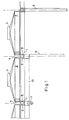
- Fig. 1 the composition of a clean room ceiling is shown, which consists of a frame arrangement of profile rails 1 and 2 suspended matter filters.
- the rails are connected to the normal ceiling on suspension devices, not shown.
- Feeds 3 for the air are shown above the suspended matter filter 2.
- the suspended matter filter 2 are accommodated in frame 4, to which rotating knives 5 are fastened.
- the knives dip into U-shaped channels 6 of the profile rails 1, which contain a fluid, not shown.
- Lights 7, flow aprons 8 or even walls 9 are attached to the profile rails 1 directly or via profile pieces.
- Intermediate ceilings 10 are shown schematically, which are also on the profile rails 1 are attached.
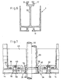
- the profile rail 1 used for the ceiling frame arrangement is shown in more detail.
- the profile rail 1 has two lateral flanges 11 and a web 12.
- a central web 13 is provided in the center of the side flanges.
- the web 12 is designed as a hollow profile and has two lateral cavities 14 and a centrally located T-groove 15 provided between them.
- the central web 13 is also designed as a hollow profile, its walls 16 extending somewhat obliquely upwards.
- the central web 13 protrudes beyond the side flanges 11 and ends in a head 17 in which laterally formed grooves 18 are provided.
- the surface 19 of the head 17 is designed as a fillet.
- the web 13 is laterally provided with fill level markings 20 which face the U-shaped channels 6 formed by the flanges 11, the web 12 and the central web 13.
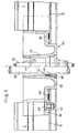
- Fig. 3 the installation and suspension of the profile rail 1 is shown, which are filled with fluid 21 in the U-shaped channels 6.
- the frames 4 of the filters 3 go directly into the rotating knives 5, which are immersed in the fluid 21, whereby they rest on the inside of the web 12 and thus form the holder for the filter 2.
- the profile rail 1 is suspended from its head 17 by means of a suspension device 22 which has two angle pieces 23, 24 which form a bracket.
- the elbows 23, 24 engage in the grooves 18.
- a bolt 25 is passed through the angle pieces 23, 24 and is clamped by means of nuts 26 and / or a screw block to the surface 19 of the head 17 which is designed as a fillet, the clamping effect of the angle pieces 23, 24 being produced at the same time.
- the bolt 25 is suspended from an eyelet 27 on a hook 28 connected to the ceiling.
- Fig. 3 also shows a possibility for fastening components to the web 12 of the profile rail.
- a profile piece 29 is fastened by means of self-clamping screws 30 inserted into the T-groove 15, an intermediate ceiling 31 being fastened to the profile piece 29 in this exemplary embodiment, and a lamp 33 being fastened via further screw connections 32.
- the profile piece 29 serving as an intermediate piece is not absolutely necessary, for example the lamp 33 can be held directly on screws accommodated in the T-slot 15.
- a connector 34 for the rails 1 is shown.
- the connecting piece 34 is designed as a cross piece, but T and angle connecting pieces can also be constructed in the same way.
- the connecting piece 34 consists of a square central part 35 and arms 36 formed thereon, a height difference between the lower surface of the central part 35 and the lower surface of the arms 36 corresponding to the height of the web 12 of the profile rail 1.
- a pipe socket 37 is provided in the middle of the middle part 35, which is used to pass lines, such as sprinkler lines 38 or 39 electrical lines.
- the connecting piece 34 is also provided with central webs 40, which, however, are solid.
- the central web 40 merges into the pipe socket 37 and is shaped into a fork 41 at the open end of the arms 36.
- the connecting piece 34 is open at the top and also has lateral flanges, so that the U-shaped channels 6 formed by the profile rails 1 can be continued around corners via a connecting piece 34.
- the connecting pieces 34 are inserted into the profile rails 1, the central webs 13 of the profile rails 1 being received in the corresponding fork 41.
- the flanges 11 of the profile rails and the webs 12 protrude beyond the central web 13 and are guided to the central part 35 of the connecting piece 34.
- a U-shaped sealing strip 48 is inserted between the inside of the web 12 of the profile rail and the outer surface of the arms, which is used to seal against the escape of the fluid 21.
- the bottom 42 of the arms 36 is connected to the web 12 of the associated profile rail on both sides of the central web 40 or the fork 41 via a fixed screw connection 43, whereby a uniform pressure is applied, so that the arms 36 do not tilt in the profile rails 1.
- An incision 44 is provided in the pipe socket 37, so that when the fluid is filled it can also get into the pipe socket interior.
- a corresponding incision 49 is provided in the fork so that the space between the fork 41 and the central web 13 of the profile rail 1 can be filled.
- a sealing ring 45 is arranged around the corresponding line 38, 39 which is pressed, for example by a screw sleeve 46 to be actuated from the clean room, against a shoulder 47 provided in the interior of the pipe socket 37.
- FIG. 6 shows a further exemplary embodiment of the profiled rail 1, which overall is made narrower than the exemplary embodiment according to FIG. 2 and the central web 50 of which is solid.
- the design of the head 17 of the central web is also changed compared to the embodiment in FIG. 2.
- the head 17 has a T-groove 51 corresponding to the T-shaped groove 15 of the web 12 of the profile rail 1 lying parallel to the ceiling, into which correspondingly shaped screws can be inserted, to which the suspension device is attached.
- FIG. 7 shows a further exemplary embodiment of the connecting piece 34.
- 5 consists of a square middle part 35, a simple bore 52 being provided in the middle of this middle part, through which the lines 38, 39 are passed.
- An empty pipe 53 must be provided for the electrical lines 39, which receives the electrical lines.
- the sprinkler pipe 38 and the empty pipe 53 are on the outside with a Provide collar 54, which serves as a stop and which is clamped by means of a threaded sleeve 46 from the clean room side.
- a sealing ring 45 can be clamped in between.
- the central webs 40 of the connecting piece 34 end on the one hand at the bore 52 and on the other hand at the ends of the arms 36 without a fork according to FIGS.
Priority Applications (1)
| Application Number | Priority Date | Filing Date | Title |
|---|---|---|---|
| AT85116128T ATE66063T1 (de) | 1984-12-28 | 1985-12-18 | Von der decke eines raumes abhaengbare modulare rahmenanordnung zur aufnahme von filtern mit fluiddichtung fuer reinraumdecken. |
Applications Claiming Priority (2)
| Application Number | Priority Date | Filing Date | Title |
|---|---|---|---|
| DE3447901 | 1984-12-28 | ||
| DE3447901A DE3447901C2 (de) | 1984-12-28 | 1984-12-28 | Von der Decke eines Raumes abhängbare modulare Rahmenanordnung zur Aufnahme von Filtern mit Fluiddichtung für Reinraumdecken |
Publications (3)
| Publication Number | Publication Date |
|---|---|
| EP0187321A2 EP0187321A2 (de) | 1986-07-16 |
| EP0187321A3 EP0187321A3 (en) | 1988-03-23 |
| EP0187321B1 true EP0187321B1 (de) | 1991-08-07 |
Family
ID=6254173
Family Applications (1)
| Application Number | Title | Priority Date | Filing Date |
|---|---|---|---|
| EP85116128A Expired - Lifetime EP0187321B1 (de) | 1984-12-28 | 1985-12-18 | Von der Decke eines Raumes abhängbare modulare Rahmenanordnung zur Aufnahme von Filtern mit Fluiddichtung für Reinraumdecken |
Country Status (9)
| Country | Link |
|---|---|
| US (1) | US4710208A (it) |
| EP (1) | EP0187321B1 (it) |
| JP (1) | JPS61211438A (it) |
| AT (1) | ATE66063T1 (it) |
| CA (1) | CA1280870C (it) |
| DE (2) | DE3447901C2 (it) |
| DK (1) | DK158101C (it) |
| FI (1) | FI83685C (it) |
| NO (1) | NO855270L (it) |
Cited By (1)
| Publication number | Priority date | Publication date | Assignee | Title |
|---|---|---|---|---|
| DE3727509A1 (de) * | 1987-08-18 | 1989-03-02 | Kessler & Luch Produkte | Filterrahmen-gitterwerk |
Families Citing this family (30)
| Publication number | Priority date | Publication date | Assignee | Title |
|---|---|---|---|---|
| JPS63187614U (it) * | 1987-05-26 | 1988-12-01 | ||
| DE8710286U1 (it) * | 1987-07-28 | 1988-08-25 | Kessler & Luch Gmbh, 6300 Giessen, De | |
| US4819549A (en) * | 1988-02-05 | 1989-04-11 | Donaldson Company Inc. | End seal for clean room ceiling supports |
| DE3827918A1 (de) * | 1988-08-17 | 1990-02-22 | Nickel Gmbh Heinrich | Laminarisator |
| DE3836147C2 (de) * | 1988-10-23 | 1996-03-21 | Ltg Lufttechnische Gmbh | Reinraumdecke |
| DE3837296A1 (de) * | 1988-11-03 | 1990-09-20 | Karl Hans Koch | Profilrasterdecke fuer wohn-, geschaefts-, ausstellungsraeume od. dgl. |
| DE3902934A1 (de) * | 1989-02-01 | 1990-08-16 | Hunter Douglas Ind Bv | Unterdecke |
| US4986050A (en) * | 1989-08-22 | 1991-01-22 | Filtra Corporation | Modular support system for a filter-type ceiling grid |
| US5613759A (en) * | 1991-06-24 | 1997-03-25 | Brod & Mcclung-Pace Co. | Light and filter support structure |
| US5454756A (en) * | 1991-08-21 | 1995-10-03 | Pace Company | Clean room ventilation system |
| US5192348A (en) * | 1991-08-21 | 1993-03-09 | Brod & Mcclung-Pace Co. | Directional air diffuser panel for clean room ventilation system |
| US5323976A (en) * | 1992-09-03 | 1994-06-28 | Johnson Louis W | Lift line connection for rock crusher components |
| US5279632A (en) * | 1992-12-17 | 1994-01-18 | International Business Machines Corporation | Planar clean room ceiling structure |
| US5540028A (en) * | 1994-07-05 | 1996-07-30 | Scott; Robert D. | HEPA filter ceiling assembly with in-situ gelation of sealant |
| DE29600210U1 (de) * | 1996-01-08 | 1996-02-29 | Meissner & Wurst | Befestigungsvorrichtung, insbesondere Rasterdecke, für Reinräume |
| DE19611817C2 (de) * | 1996-03-26 | 2000-10-26 | Schako Metallwarenfabrik | Filterkasten |
| DE19641127A1 (de) * | 1996-10-05 | 1998-04-09 | Meissner & Wurst | Reinraumdecke, vorzugsweise Rasterdecke |
| KR100234908B1 (ko) * | 1997-08-26 | 1999-12-15 | 윤종용 | 청정실용 필터 |
| FR2779464B1 (fr) | 1998-06-09 | 2000-08-25 | Clestra Cleanroom | Perfectionnement aux plafonds suspendus |
| US7513086B2 (en) * | 2006-03-17 | 2009-04-07 | Mod-Tec, Llc | Fan filter mounting frame |
| US8336271B2 (en) * | 2006-03-17 | 2012-12-25 | Mod-Tec, Llc | Fan filter mounting frame |
| US8105409B2 (en) * | 2009-01-30 | 2012-01-31 | General Electric Company | Filter retention system |
| US8052770B2 (en) * | 2009-03-13 | 2011-11-08 | General Electric Company | Filter retainer for turbine engine |
| US8048186B2 (en) * | 2009-04-02 | 2011-11-01 | General Electric Company | Filter retention systems and devices |
| CN104132445A (zh) * | 2014-06-16 | 2014-11-05 | 无锡零界净化设备有限公司 | 一种自定位高效风口结构 |
| CN105157191A (zh) * | 2015-10-08 | 2015-12-16 | 无锡零界净化设备有限公司 | 一种净化厂房的送风口及其加工工艺 |
| US10119469B2 (en) | 2016-09-15 | 2018-11-06 | General Electric Company | Method and apparatus for modularized inlet silencer baffles |
| US10722990B2 (en) | 2016-09-15 | 2020-07-28 | General Electric Company | Method for installing and removing modularized silencer baffles |
| CN108278157B (zh) | 2017-01-06 | 2022-08-02 | 通用电气公司 | 用于改进的入口消音挡板的系统和方法 |
| CN108278158B (zh) | 2017-01-06 | 2022-05-13 | 通用电气公司 | 用于改进的入口消音挡板的系统和方法 |
Family Cites Families (11)
| Publication number | Priority date | Publication date | Assignee | Title |
|---|---|---|---|---|
| US3471981A (en) * | 1966-06-20 | 1969-10-14 | Luminous Ceilings Inc | Suspended ceiling construction with interconnected baffles and wireways |
| US3848385A (en) * | 1970-06-12 | 1974-11-19 | Nat Ceiling Corp | Modular ceiling construction |
| US3685235A (en) * | 1970-09-21 | 1972-08-22 | Bajer Ind Inc | Suspended ceiling system including a grid network |
| US3750374A (en) * | 1971-06-07 | 1973-08-07 | Delbag Luftfilter Gmbh | Gas filters |
| CH578660A5 (it) * | 1973-11-15 | 1976-08-13 | Henggeler Aldo | |
| US4081931A (en) * | 1975-01-11 | 1978-04-04 | Kiyotaka Miyoshi | Anti-smoke hanging wall and construction method |
| US4019300A (en) * | 1975-08-04 | 1977-04-26 | Roblin Industries, Inc. | Suspended ceiling structure |
| US4233044A (en) * | 1976-05-13 | 1980-11-11 | Flanders Filters, Inc. | Self-cleaning fluid sealed air filter |
| US4438613A (en) * | 1981-06-25 | 1984-03-27 | Decoustics Limited | Suspended ceiling panel system |
| US4570391A (en) * | 1982-12-20 | 1986-02-18 | Flanders Filters, Inc. | Connector for a filter bank supporting framework and method of assembling same |
| US4545793A (en) * | 1983-12-22 | 1985-10-08 | Allis-Chalmers Corporation | Air filter system with supporting and sealing grid |
-
1984
- 1984-12-28 DE DE3447901A patent/DE3447901C2/de not_active Expired - Fee Related
-
1985
- 1985-12-18 DE DE8585116128T patent/DE3583734D1/de not_active Expired - Lifetime
- 1985-12-18 AT AT85116128T patent/ATE66063T1/de not_active IP Right Cessation
- 1985-12-18 EP EP85116128A patent/EP0187321B1/de not_active Expired - Lifetime
- 1985-12-20 DK DK598785A patent/DK158101C/da not_active IP Right Cessation
- 1985-12-23 CA CA000498547A patent/CA1280870C/en not_active Expired - Lifetime
- 1985-12-23 NO NO855270A patent/NO855270L/no unknown
- 1985-12-23 FI FI855144A patent/FI83685C/fi not_active IP Right Cessation
- 1985-12-27 US US06/814,227 patent/US4710208A/en not_active Expired - Fee Related
- 1985-12-28 JP JP60299799A patent/JPS61211438A/ja active Pending
Cited By (1)
| Publication number | Priority date | Publication date | Assignee | Title |
|---|---|---|---|---|
| DE3727509A1 (de) * | 1987-08-18 | 1989-03-02 | Kessler & Luch Produkte | Filterrahmen-gitterwerk |
Also Published As
| Publication number | Publication date |
|---|---|
| FI83685B (fi) | 1991-04-30 |
| DE3447901A1 (de) | 1986-07-10 |
| DE3447901C2 (de) | 1994-07-07 |
| EP0187321A2 (de) | 1986-07-16 |
| CA1280870C (en) | 1991-03-05 |
| DK598785A (da) | 1986-06-29 |
| DE3583734D1 (de) | 1991-09-12 |
| DK598785D0 (da) | 1985-12-20 |
| DK158101C (da) | 1990-08-20 |
| DK158101B (da) | 1990-03-26 |
| FI855144A0 (fi) | 1985-12-23 |
| EP0187321A3 (en) | 1988-03-23 |
| NO855270L (no) | 1986-06-30 |
| JPS61211438A (ja) | 1986-09-19 |
| FI83685C (fi) | 1991-08-12 |
| FI855144A (fi) | 1986-06-29 |
| ATE66063T1 (de) | 1991-08-15 |
| US4710208A (en) | 1987-12-01 |
Similar Documents
| Publication | Publication Date | Title |
|---|---|---|
| EP0187321B1 (de) | Von der Decke eines Raumes abhängbare modulare Rahmenanordnung zur Aufnahme von Filtern mit Fluiddichtung für Reinraumdecken | |
| EP3384568B1 (de) | Rahmenprofil für ein rahmengestell eines schaltschranks und ein entsprechendes rahmengestell | |
| DE102008012460C5 (de) | Bodenplatte oder Kabelverteilerschrank mit einer Bodenplatte und Montageverfahren | |
| DE3802309C2 (it) | ||
| DE69827101T2 (de) | System von Elementen zur Herstellung einer zusammensetzbaren Rohrleitung aus extrudierten Rohrabschnitten | |
| EP0332672A1 (de) | Deckenverkleidung | |
| EP0933488A2 (de) | Deckenraster für Reinräume | |
| DE4003992C2 (de) | Gerätetragarm für Steuertafeln, Steuergehäuse o. dgl. | |
| DE3101947A1 (de) | Duschtrennwand | |
| WO2006074973A1 (de) | Modulare fassade für gebäude, glasauflagedichtung und schraube | |
| DE102008063482B4 (de) | Gehäuse für Lüftungs- und Klimageräte | |
| DE19709823C2 (de) | Modulsystem für Zwischendeckenkonstruktionen | |
| DE2412735C3 (de) | Aus stranggepreßten, Heizfluid führenden Gliedern baukastenartig zusammengesetzter Heizkörper | |
| DE19630807C1 (de) | Tragarm für Steuergeräte, Kommandogehäuse und dergleichen | |
| DE3727509C2 (de) | Filterrahmen-Gitterwerk | |
| AT526536B1 (de) | Halteschiene für Flächenheizungs- und/oder Flächenkühlungsrohre | |
| DE3616896C2 (de) | Rastertrennwand für Reinräume | |
| DE3715213A1 (de) | Reinraumdeckensystem | |
| DE4303369C1 (de) | Vorrichtung zum Überbrücken einer Dehnfuge | |
| EP3757305B1 (de) | Arbeitsraum | |
| EP0262515B1 (de) | Filterrahmen-Gitterwerk | |
| DE2739364A1 (de) | Bauelementsystem | |
| DE4337269C1 (de) | Filterwand oder -decke für reinraumtechnische Anlagen | |
| DE1690188C3 (de) | Kombinierte Anschlußeinrichtung für die Versorgung von Abnahmestellen | |
| DE2305612C3 (de) | Leichtmetall-Hohlprofil für einen Abstütz- und/oder Knotenpunkt einer Rahmenkonstruktion |
Legal Events
| Date | Code | Title | Description |
|---|---|---|---|
| PUAI | Public reference made under article 153(3) epc to a published international application that has entered the european phase |
Free format text: ORIGINAL CODE: 0009012 |
|
| AK | Designated contracting states |
Kind code of ref document: A2 Designated state(s): AT BE CH DE FR GB IT LI NL SE |
|
| PUAL | Search report despatched |
Free format text: ORIGINAL CODE: 0009013 |
|
| AK | Designated contracting states |
Kind code of ref document: A3 Designated state(s): AT BE CH DE FR GB IT LI NL SE |
|
| 17P | Request for examination filed |
Effective date: 19880422 |
|
| 17Q | First examination report despatched |
Effective date: 19891013 |
|
| GRAA | (expected) grant |
Free format text: ORIGINAL CODE: 0009210 |
|
| RAP1 | Party data changed (applicant data changed or rights of an application transferred) |
Owner name: ABB FLAEKT AB |
|
| AK | Designated contracting states |
Kind code of ref document: B1 Designated state(s): AT BE CH DE FR GB IT LI NL SE |
|
| PG25 | Lapsed in a contracting state [announced via postgrant information from national office to epo] |
Ref country code: SE Effective date: 19910807 |
|
| REF | Corresponds to: |
Ref document number: 66063 Country of ref document: AT Date of ref document: 19910815 Kind code of ref document: T |
|
| REF | Corresponds to: |
Ref document number: 3583734 Country of ref document: DE Date of ref document: 19910912 |
|
| ITF | It: translation for a ep patent filed |
Owner name: BARZANO' E ZANARDO MILANO S.P.A. |
|
| GBT | Gb: translation of ep patent filed (gb section 77(6)(a)/1977) | ||
| ET | Fr: translation filed | ||
| PG25 | Lapsed in a contracting state [announced via postgrant information from national office to epo] |
Ref country code: AT Effective date: 19911231 |
|
| PLBE | No opposition filed within time limit |
Free format text: ORIGINAL CODE: 0009261 |
|
| STAA | Information on the status of an ep patent application or granted ep patent |
Free format text: STATUS: NO OPPOSITION FILED WITHIN TIME LIMIT |
|
| 26N | No opposition filed | ||
| PGFP | Annual fee paid to national office [announced via postgrant information from national office to epo] |
Ref country code: FR Payment date: 20011212 Year of fee payment: 17 |
|
| PGFP | Annual fee paid to national office [announced via postgrant information from national office to epo] |
Ref country code: GB Payment date: 20011219 Year of fee payment: 17 |
|
| PGFP | Annual fee paid to national office [announced via postgrant information from national office to epo] |
Ref country code: NL Payment date: 20011228 Year of fee payment: 17 |
|
| REG | Reference to a national code |
Ref country code: GB Ref legal event code: IF02 |
|
| PGFP | Annual fee paid to national office [announced via postgrant information from national office to epo] |
Ref country code: CH Payment date: 20020104 Year of fee payment: 17 |
|
| PGFP | Annual fee paid to national office [announced via postgrant information from national office to epo] |
Ref country code: DE Payment date: 20020109 Year of fee payment: 17 |
|
| PGFP | Annual fee paid to national office [announced via postgrant information from national office to epo] |
Ref country code: BE Payment date: 20020213 Year of fee payment: 17 |
|
| PG25 | Lapsed in a contracting state [announced via postgrant information from national office to epo] |
Ref country code: GB Free format text: LAPSE BECAUSE OF NON-PAYMENT OF DUE FEES Effective date: 20021218 |
|
| PG25 | Lapsed in a contracting state [announced via postgrant information from national office to epo] |
Ref country code: LI Free format text: LAPSE BECAUSE OF NON-PAYMENT OF DUE FEES Effective date: 20021231 Ref country code: CH Free format text: LAPSE BECAUSE OF NON-PAYMENT OF DUE FEES Effective date: 20021231 Ref country code: BE Free format text: LAPSE BECAUSE OF NON-PAYMENT OF DUE FEES Effective date: 20021231 |
|
| BERE | Be: lapsed |
Owner name: *ABB FLAKT A.B. Effective date: 20021231 |
|
| PG25 | Lapsed in a contracting state [announced via postgrant information from national office to epo] |
Ref country code: NL Free format text: LAPSE BECAUSE OF NON-PAYMENT OF DUE FEES Effective date: 20030701 Ref country code: DE Free format text: LAPSE BECAUSE OF NON-PAYMENT OF DUE FEES Effective date: 20030701 |
|
| GBPC | Gb: european patent ceased through non-payment of renewal fee |
Effective date: 20021218 |
|
| REG | Reference to a national code |
Ref country code: CH Ref legal event code: PL |
|
| NLV4 | Nl: lapsed or anulled due to non-payment of the annual fee |
Effective date: 20030701 |
|
| PG25 | Lapsed in a contracting state [announced via postgrant information from national office to epo] |
Ref country code: FR Free format text: LAPSE BECAUSE OF NON-PAYMENT OF DUE FEES Effective date: 20030901 |
|
| REG | Reference to a national code |
Ref country code: FR Ref legal event code: ST |