EP0184679B1 - Verfahren zur Herstellung eines Graphitfluorids zur Verwendung in einer elektrochemischen Zelle - Google Patents
Verfahren zur Herstellung eines Graphitfluorids zur Verwendung in einer elektrochemischen Zelle Download PDFInfo
- Publication number
- EP0184679B1 EP0184679B1 EP85114365A EP85114365A EP0184679B1 EP 0184679 B1 EP0184679 B1 EP 0184679B1 EP 85114365 A EP85114365 A EP 85114365A EP 85114365 A EP85114365 A EP 85114365A EP 0184679 B1 EP0184679 B1 EP 0184679B1
- Authority
- EP
- European Patent Office
- Prior art keywords
- graphite fluoride
- graphite
- residual carbon
- carbon
- decomposition
- Prior art date
- Legal status (The legal status is an assumption and is not a legal conclusion. Google has not performed a legal analysis and makes no representation as to the accuracy of the status listed.)
- Expired - Lifetime
Links
Images


Classifications
-
- H—ELECTRICITY
- H01—ELECTRIC ELEMENTS
- H01M—PROCESSES OR MEANS, e.g. BATTERIES, FOR THE DIRECT CONVERSION OF CHEMICAL ENERGY INTO ELECTRICAL ENERGY
- H01M4/00—Electrodes
- H01M4/02—Electrodes composed of, or comprising, active material
- H01M4/36—Selection of substances as active materials, active masses, active liquids
- H01M4/58—Selection of substances as active materials, active masses, active liquids of inorganic compounds other than oxides or hydroxides, e.g. sulfides, selenides, tellurides, halogenides or LiCoFy; of polyanionic structures, e.g. phosphates, silicates or borates
- H01M4/583—Carbonaceous material, e.g. graphite-intercalation compounds or CFx
-
- C—CHEMISTRY; METALLURGY
- C01—INORGANIC CHEMISTRY
- C01B—NON-METALLIC ELEMENTS; COMPOUNDS THEREOF; METALLOIDS OR COMPOUNDS THEREOF NOT COVERED BY SUBCLASS C01C
- C01B32/00—Carbon; Compounds thereof
- C01B32/10—Carbon fluorides, e.g. [CF]nor [C2F]n
-
- H—ELECTRICITY
- H01—ELECTRIC ELEMENTS
- H01M—PROCESSES OR MEANS, e.g. BATTERIES, FOR THE DIRECT CONVERSION OF CHEMICAL ENERGY INTO ELECTRICAL ENERGY
- H01M4/00—Electrodes
- H01M4/02—Electrodes composed of, or comprising, active material
- H01M4/36—Selection of substances as active materials, active masses, active liquids
- H01M4/58—Selection of substances as active materials, active masses, active liquids of inorganic compounds other than oxides or hydroxides, e.g. sulfides, selenides, tellurides, halogenides or LiCoFy; of polyanionic structures, e.g. phosphates, silicates or borates
- H01M4/583—Carbonaceous material, e.g. graphite-intercalation compounds or CFx
- H01M4/5835—Comprising fluorine or fluoride salts
-
- H—ELECTRICITY
- H01—ELECTRIC ELEMENTS
- H01M—PROCESSES OR MEANS, e.g. BATTERIES, FOR THE DIRECT CONVERSION OF CHEMICAL ENERGY INTO ELECTRICAL ENERGY
- H01M6/00—Primary cells; Manufacture thereof
- H01M6/14—Cells with non-aqueous electrolyte
- H01M6/16—Cells with non-aqueous electrolyte with organic electrolyte
-
- Y—GENERAL TAGGING OF NEW TECHNOLOGICAL DEVELOPMENTS; GENERAL TAGGING OF CROSS-SECTIONAL TECHNOLOGIES SPANNING OVER SEVERAL SECTIONS OF THE IPC; TECHNICAL SUBJECTS COVERED BY FORMER USPC CROSS-REFERENCE ART COLLECTIONS [XRACs] AND DIGESTS
- Y02—TECHNOLOGIES OR APPLICATIONS FOR MITIGATION OR ADAPTATION AGAINST CLIMATE CHANGE
- Y02E—REDUCTION OF GREENHOUSE GAS [GHG] EMISSIONS, RELATED TO ENERGY GENERATION, TRANSMISSION OR DISTRIBUTION
- Y02E60/00—Enabling technologies; Technologies with a potential or indirect contribution to GHG emissions mitigation
- Y02E60/10—Energy storage using batteries
Definitions
- This invention relates to a process for producing a graphite fluoride for use in an electrochemical cell comprising a negative electrode having as the active material a light metal, such as an alkali metal, an electrolyte in which the negative electrode is not dissolved, and a positive electrode having as the active material a graphite fluoride.
- the electrochemical cell with the graphite fluoride accord to the present invention is extremely excellent in not only discharge potential and discharge capacity but also flatness of discharge potential.
- Electrochemical cells of (CF) n and (C 2 F) n each have advantages on one hand, and have drawbacks on the other hand.
- the former has an advantage that the discharge capacity is large because the fluoride content is high.
- the former had disadvantages that the overvoltage is high and the discharge potential is not sufficient and that the production of (CF) n is inevitably and disadvantageously accompanied by decomposition and, therefore, it is difficult to produce (CF) n in high yield.
- the latter has advantages that (C 2 F) n can be advantageously produced in a yield as high as 100% and that the overvoltage is low and the discharge potential is high.
- the latter has a disadvantage that the discharge capacity is smaller than that of the former because the fluorine content of (C 2 F) n is a half, in mole, that of (CF) n'
- the advantages and disadvantages of (CF) n and (C 2 F) n will be explained in detail.
- the graphite fluoride is a high molecular polycristalline compound and has not been obtained in the form of a single crystal.
- electrochemical cells of (CF) n and (C 2 F) n in which there are respectively used (CF) n and (C 2 F) n having relatively high crystallinity the discharge characteristics are described below.
- both the electrochemical cell of (CF) n and the electrochemical cell of (C 2 F) n generally have the following discharge characteristics:
- the crystallinity of a raw carbon material influences the crystallinity of a graphite fluoride produced therefrom.
- the crystallite size of the graphite fluoride crystal in the direction of a c-axis is also large. Therefore, if such raw carbon material is used for producing a graphite fluoride, the resulting graphite fluoride comprises graphite fluoride crystallites which are large in crystallite size not only in the direction of an a,b-axis but also in the direction of a c-axis.
- a graphite fluoride having a large crystallite size in the direction of an a,b-axis has not a small crystallite size in the direction of a c-axis but a large crystallite size in the direction of a c-axis. Therefore, it has been difficult to produce a graphite fluoride comprising graphite fluoride crystallites which are large in crystallite size in the direction of an a,b-axis and small in crystallite size in the direction of a c-axis. In other words, it has been difficult to produce a graphite fluoride which exhibits not only excellent discharge characteristics with respect to flatness of discharge potential but also low overvoltage and high discharge potential.
- (C2F) used as an active material cannot be produced from any other carbon material than a graphite having high crystallinity and a long period of time is needed for the production of (C 2 F) n due to low reaction temperature.
- a raw carbon material having low crystallinity e.g., petroleum cokes
- can be fluorinated at low temperature to produce (CF) n but is decomposed to lower fluorocarbons at high temperature.
- the present inventors In order to obtain an active material for an electrochemical cell which is excellent in discharge characteristics, the present inventors have made extensive and intensive studies. As a result, the present inventors have unexpectedly found that when a graphite fluoride produced by fluorinating a decomposition residual carbon which has been obtained by decomposing a covalent graphite intercalation compound in which an intercalant is bonded to a carbon atom by covalent bond is used as an active material of an electrochemical cell, the electrochemical cell exhibits not only high discharge potential and low over-voltage but also excellent discharge characteristics with respect to flatness of discharge voltage, discharge capacity and freedom of leakage as compared with the electrochemical cells of conventional graphite fluorides.
- the present invention has been made based on such a novel finding.
- a graphite fluoride for use in an electrochemical cell comprising a negative electrode having as the active material a light metal, an electrolyte, and a positive electrode having as the active material a graphite fluoride produced by fluorinating a decomposition residual carbon which has been obtained by decomposing a covalent graphite intercalation compound in which an intercalant is bonded to the carbon atom by a covalent bond.
- a covalent graphite intercalation compound to be used as a raw carbon material will be explained below.
- the covalent graphite intercalation compound comprises a carbon atom and an intercalant bonded to the carbon atom by a covalent bond.
- the intercalant bonded to the carbon atom by a covalent bond there may be mentioned, for example, a fluorine atom, an oxygen atom, etc.
- a fluorine atom for example, a fluorine atom, an oxygen atom, etc.
- a graphite fluoride As the covalent graphite intercalation compound in which the intercalant is a fluorine atom, there may be mentioned a graphite fluoride.
- the graphite fluoride includes conventional (CF) n , (C 2 F) n and mixtures thereof.
- As the covalent graphite intercalation compound in which the intercalant is an oxygen atom there may be mentioned a graphitic oxide.
- the decomposition residual carbon is obtained by heat-decomposing the above-mentioned covalent graphite intercalation compound.
- the decomposition residual carbon obtained from a graphite fluoride will be explained below.
- conventional (CF) n , (C2F)n and mixtures thereof may be used as the graphite fluoride for obtaining the decomposition residual carbon.
- the graphite fluoride may be prepared as follows. The graphite fluoride is obtained by the fluorination of a carbon material, but the composition of a graphite fluoride formed by the fluorination of a carbon material varies depending on the reaction temperature and the kind of crystallinity of the raw carbon material.
- (CF) n may be produced by reacting an amorphous carbon material, such as petroleum coke, with fluorine at a temperature of about 200°C to about 450°C, and (CF) n or (CF) n -rich mixtures of (CF) n and (C 2 F) n may be produced by reacting a crystalline carbon material, such as natural and artificial graphites, with fluorine at a temperature of about 500°C to about 630°C.
- the reason for conducting the fluorination reaction below 630°C is that the decomposition of (CF) n is promoted over 630°C and that there is not available a material for the reaction vessel which can withstand fluorine corrosion at such high temperatures.
- (CF) n Compounds of (CF) n are produced with varied crystallinities and those having high crystallinities are white solids.
- (C 2 F) “ or (C 2 F) n -rich mixtures of (C 2 F) " and (CF) n may be produced by reacting a crystalline carbon material, such as natural and artificial graphites, with fluorine at a temperature of about 300°C to about 500°C.
- the color of (C 2 F) n is black under the conditions for the formation thereof and changes from black through gray to white with heat treatment thereof at elevated temperature of up to about 600°C with increase of crystallinity.
- the resulting graphite fluoride product is (CF) n -rich in the event that the fluorination is conducted at a temperature higher than about 500°C, whereas it is (C 2 F) n -rich in the event that the fluorination is conducted at a temperature of up to about 500°C.
- the boundary temperature is not about 500°C but 470°C.
- the reaction time is not critical. If complete fluorination of a carbon material is intended, the fluorination reaction may be continued until weight increase of the graphite fluoride product is no longer recognized. Further, there is an advantageous method in which a carbon material is reacted with fluorine to form a graphite fluoride product which contains a carbon material remaining unreacted, and then, the graphite fluoride product is subjected to sifting with a sieve to recover a graphite fluoride from the carbon material remaining unreacted (see British Patent Application Laid-Open Specification No. 2104883).
- a carbon material either crystalline or amorphous carbon materials may be used.
- suitable carbon material there can be mentioned, for example, an artificial graphite, natural graphite, petroleum coke, pitch coke, activated carbon, carbon black and fibrous carbon.
- the above carbon materials are available on the market.
- petroleum cokes (amorphous carbon) with varied particle or grain diameters may be produced by expelling voltile components from raw petroleum oil, polymerizing the resuting oil to give raw coke, heating the resulting raw coke in a rotary kiln or Riedhammer calcination furnace at about 1400°C to obtain calcined coke and grinding the obtained calcined coke to a predetermined size.
- artificial graphites crystalline carbon
- fluorine gas produced by electrolysis of a KF-2HF molten salt may either be used as such or used after removing HF which is contained as an impurity.
- fluorine gas from a commercially available fluorine gas bomb may also be conveniently utilized.
- the fluorination reaction may be effected in an atmosphere of either fluorine gas alone or a mixture of fluorine gas and a diluent gas under an F 2 partial pressure of 100 to 760 mm Hg (13.3 kPa to 101 kPa).
- the fluorination reaction is effected under a pressure of 760 mm Hg (101 kPa).
- the suitable diluent gas there can be mentioned nitrogen gas, argon gas, neon gas, air, perfluorohydrocarbon gas and carbon dioxide gas.
- the composition of a graphite fluoride to be formed by the fluorination of a carbon material varies depending on the reaction temperature and the kind or crystallinity of the raw carbon materials.
- the thus obtained graphite fluoride is then decomposed to prepare a decomposition residual carbon.
- Decomposition of a graphite fluoride is effected by heating. That is, the decomposition of a graphite fluoride may be done by heating to a temperature of about 580 to 620°C in an atmosphere of an inert gas such as argon gas, nitrogen gas and the like or air or under vacuum. The temperature elevation rate is not critical. The temperature at which a graphite fluoride begins to decompose varies depending on the raw carbon material used.
- the decomposition of a graphite fluoride generally begins at the time that the temperature is elevated to about 400 to 500°C and completes at the time that the temperature reaches the above-mentioned range, i.e. about 580 to 620°C.
- the decomposition temperatures may be measured by differential thermal analysis.
- a decomposition residual carbon from a graphite fluoride may be obtained by preparing and isolating a graphite fluoride and then decomposing the isolated graphite fluoride. The thus obtained decomposition residual carbon is employed for preparing a specific graphite fluoride to be used as an active material in the present invention.
- a decomposition residual carbon obtained by the thermal decomposition of a conventional graphite fluoride which decomposition accompanies the production of the conventional graphite fluoride.
- the decomposition residual carbon obtained by preparing and isolating a graphite fluoride and then decomposing the isolated graphite fluoride may preferably be employed.
- the thus obtained decomposition residual carbon contains about 3 to 5% by weight of fluorine, which does not have any adverse effect on the subsequent fluorination step for preparing a graphite fluoride to be used as the active material in the present invention.
- a graphitic oxide may be obtained by subjecting a crystalline or amorphous carbon to oxidation treatment according to any conventionally known methods.
- any conventionally known methods there may be mentioned, for example, those proposed by W. S. Hummers et al [W. S. Hummers et al, J. Amer. Chem. Soc., p. 1339 (1958)], S. Okada et al [Zairyo Shiken (Test of Materials) vol. 2, No. 8, p. 363-366 (1953)], O. W. Storey [0. W. Storey, Trans. Amer. Electrochem. Soc., vol. 53, p.
- a graphitic oxide may be prepared by heating a mixture comprising as a carbon material a crystalline or amorphous carbon, a strong acid type oxidant and water at a temperature not exceeding 120°C, preferably at about 100°C.
- a carbon material there may be mentioned, for example, an artificial graphite, natural graphite, petroleum coke, activated carbon, carbon black and fibrous carbon.
- the size of a carbon material is not critical.
- a wide range of particle sizes of carbon materials that is, from a particulate carbon material having a particle size of about 10 pm to a flaky carbon material having a size of about several mm.
- a strong acid type oxidant any strong acid type oxidant used for ordinary oxidation treatment may be employed without any special restrictions.
- a mixture of a salt such as potassium permanganate, potassium chlorate and potassium dichromate and a strong acid such as a fuming sulfuric acid and a fuming nitric acid may be used as the strong acid type oxidant.
- the reaction time for preparing a graphitic oxide is not critical.
- the formation of a graphitic oxide may be recognized by observing the color of the reaction mixture.
- the reaction for preparing a graphitic oxide completes after 2 to 20 minutes from the initiation of the reaction.
- the amount ratio of a carbon material, a strong acid type oxidant and water is not critical. However, if the proportion of water is too high, it is possible for a graphitic oxide not to be formed in good yield.
- An appropriate ratio may be decided according to the results of preliminary tests in which the oxidation reactions for producing a graphitic oxide are performed with varied ratios of the raw materials and the yields are judged by observing the color of the reaction mixture.
- the reaction mixture comprising a carbon material, a strong acid type oxidant and water may be prepared by mixing the carbon material, the strong acid type oxidant and water at once, or by adding water to a mixture which has been prepared in advance by immersing the carbon material in the strong acid type oxidant.
- the reaction mixture is obtained by first immersing a carbon material in a strong acid type oxidant comprising a fuming sulfuric acid, sodium nitrate and potassium permanganate and then adding water thereto.
- a carbon material and sodium nitrate are mixed and a fuming sulfuric acid is then added thereto.
- potassium permanganate is added to the mixture while cooling.
- the thus formed graphitic oxide is taken out of the reaction mixture by, for example, filtration or the like and then washed with an alcohol such as methanol and ethanol.
- the obtained graphitic oxide assumes a black or blackish brown color.
- a graphitic oxide may also be prepared by customary electrolytic oxidation technique.
- the thus obtained graphitic oxide is then decomposed to obtain a decomposition residual carbon.
- Decomposition of a graphitic oxide is effected by heating. That is, the decomposition of a graphitic oxide may be done by elevating the temperature to about 200 to 400°C at a temperature elevation rate of about 1.0°C/min or less, preferably 0.2°C/min or less in an atmosphere of an inert gas such as an argon gas and a nitrogen gas or in an atmosphere of air, and subsequently in vacuo at about 400 to 500°C for about 1 to 3 hours. If the temperature elevation rate is 1.0°C/min or higher, it is dangerous because the graphitic oxide decomposes explosively.
- a decomposition residual carbon may be obtained by subjecting a crystalline or amorphous carbon to treatment with an oxidizing medium comprising a strong acid type oxidant and water to obtain an oxidation reaction mixture containing a graphitic oxide, and heating the oxidation reaction mixture up to from 120°C to 230°C so that the graphitic oxide in the oxidation reaction mixture is decomposed to form a decomposition residual carbon, followed by separation of the decomposition residual carbon.
- the oxidation reaction mixture containing a graphitic oxide there may be employed, for example, a method in which the oxidation reaction mixture is heated as such, and a method in which water is additionally added to the oxidation reaction mixture to elevate the temperature of the reaction mixture by hydration heat produced by the hydration of the added water and the acid in the mixture.
- the latter method is advantageous that a decomposition residual carbon can be produced more speedily than by the former method.
- the amount of water to be further added is not critical.
- the heating of the oxidation reaction mixture may be effected by the hydration heat only.
- the heating of the oxidation reaction mixture may also be partially performed by hydration heat produced by adding water to the oxidation reaction mixture.
- hydration heat generated may be insufficient for elevating the temperature of the oxidation reaction mixture up to from 12 to about 230°C.
- the other auxiliary heat source may be used at the same time.
- the temperature elevation rate for heating the oxidation reaction mixture is not critical.
- the reaction time after the temperature of the oxidation reaction mixture has reached a desired level is also not critical and depends on the temperature elevation rate.
- a decomposition residual carbon may be obtained by maintaining the elevated temperature for about 2 minutes or more. However, it may be possible to obtain a decomposition residual carbon within 2 minutes at the elevated temperature if the temperature of the reaction mixture has been elevated at a relatively low temperature elevation rate.
- the above-mentioned method in which a decomposition residual carbon is obtained by heating the oxidation reaction mixture containing a graphitic oxide without isolating the graphitic oxide from the oxidation reaction mixture is advantageous because there is no danger that the graphitic oxide decomposes explosively since the decomposition of the graphitic oxide is effected in a liquid medium, and because the step for isolating the formed graphitic oxide from the oxidation reaction mixture can be omitted.
- the drying conditions are not critical. For example, the drying may be effected at about 100 to 140°C for several hours in vacuo.
- the thus obtained decomposition residual carbon from a graphitic oxide contains about 5 to 25% by weight of oxygen, which does not have any adverse effect on the subsequent fluorination process for producing a graphite fluoride to be used as an active material in the present invention.
- the decomposition residual carbon obtained by decomposing a covalent graphite intercalation compound such as a graphite fluoride, graphitic oxide or the like assumes a black color and has a specific structure. That is, the crystallite size of the decomposition residual carbon crystal in the c-direction is extremely small as compared with those of a natural graphite, artificial graphite and the like, and there is a great disorder in, for example, stacking of the crystallite layers of the decomposition residual carbon.
- the crystallite size in the a,b-direction is as large as several times to several ten times that in the c-direction.
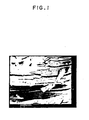
- the specific structure of the decomposition residual carbon may be recognized from a scanning electron micrograph or from data of the lattice constants and crystallite size.
- Fig. 1 is shown a scanning electron microphotograph (2000-magnification) of a decomposition residual carbon prepared by heating (C 2 F) " (F/C ratio: 0.65), which is obtained by fluorination of a natural graphite from Madagascar at 350°C for 21 days, to 600°C at a temperature elevation rate of about 5°C/min in an atmosphere of an argon gas.
- Table 1 is given data on the lattice constants and the crystallite size of the above-mentioned decomposition residual carbon obtained from the above (C 2 F) n in comparison with those of a natural graphite from Madagascar, a petroleum coke which has been heat-treated at 2800°C, a petroleum coke which has not been heat-treated, an expanded graphite prepared from an intercalation compound of a graphite with HN0 3 (in which the intercalant is bonded to the carbon by an ionic bond) and an expanded graphite prepared from a ternary intercalation compound of a graphite with MgF 2 and F 2 (in which the intercalants are bonded to the carbon by an ionic bond).
- the measurement was effected according to the method of measuring the lattice constants and crystallite size of carbon materials established by the 117th Committee of the Japan Society for the Promotion of Science.
- the obtained decomposition residual carbon is fluorinated to prepare a novel graphite fluoride to be used as the active material for an electrochemical cell of the present invention.
- An explanation will be given below with respect to the fluorination of a decomposition residual carbon. The following will be mentioned only as examples, and they should not be construed to be limiting method for preparing the specific graphite fluoride to be used for an electrochemical cell of the present invention.
- the graphite fluoride may also be prepared by electrolytic fluorination.
- the fluorination of the decomposition residual carbon may be performed in a fluorine stream at a temperature of from about 20 to 550°C.
- the fluorination temperature is generally in the range of from 350 to 550°C, preferably 380 to 520°C, more preferably 400 to 500°C.
- the fluorination temperature varies depending on the kind of the carbon material which has been used for preparing the graphitic oxide.
- the fluorination temperature for the decomposition residual carbon generally is in the range of 300 to 500°C, preferably 350 to 450°C which is relatively high as compared with that in the case where the graphitic oxide has been prepared from a petroleum coke.
- the fluorination temperature is in the range of from 20 to 550°C, preferably 100 to 450°C, more preferably 150 to 400°C.
- the flow rate of the fluorine stream is not critical and varies depending on the amount of the decomposition residual carbon. For example, several to several hundred gram of a decomposition residual carbon may be fluorinated at a flow rate of the fluorine stream of 10 to 50 ml/min. Usually the fluorination reaction is effected under a fluorine pressure of 100 to 760 mmHg (13.3 to 101 kPa).
- the fluorination reaction of the decomposed residual carbon is terminated at the time that heat generation by the fluorination reaction of the carbon becomes not recognized, which time may be determined, for example, by tracing the temperature change in the reaction vessel.
- the reaction time for the fluorination varies depending on the amount of the decomposition residual carbon and on the flow rate of the fluorine stream, but is generally from several ten minutes to about 6 hours.
- the fluorination reaction is effected at a temperature as high as about 500 to 550°C, since the fluorination reaction is accompanied by an exothermic decomposition reaction to a small extent, the generation of heat by the fluorination reaction and that by the decomposition reaction occur at the same time.
- the graphite fluoride may be prepared by fluorinating a decomposition residual carbon obtained from a covalent graphite intercalation compound, such as grahite fluoride and a graphitic oxide.
- a graphitic oxide is advantageously employed because it is not necessary to use expensive fluorine gas for the preparation thereof.
- the method in which the preparation and decomposition of the graphitic oxide is performed in a single vessel is advantageously employed because the procedures can be continuously and easily effected.
- an electrochemical cell in which the graphite fluoride produced from a graphitic oxide by such a method is used as the active material has markedly excellent discharge characteristics.
- the thus obtained novel class of graphite fluoride has an F/C ratio of 0.8 to 1.2 with respect to those obtained by fluorination at high temperatures, for example, 450 to 550°C.
- the graphite fluoride to be used in the present invention assumes a color of black to blackish brown or gray, which color is different from the color of the conventional (CF) n .
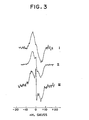
- the reason why the present novel graphite fluoride assumes such a color of black to blackish brown or gray is cnsidered to be that aromatic condensed carbocycles (hereinafter often referred to as "defects") are present therein.
- the conventional (CF) n as shown in Fig. 3 was prepared by directly fluorinating a natural graphite from Madagascar at 350°C, and the conventional (C 2 F) n as shown in Fig. 3 was also prepared by directly fluorinating a natural graphite from Madagascar at 350°C.
- the spectrum of the specific graphite fluoride to be used in the present invention indicates a sharp and narrow peak derived from the absorbed fluorine as opposed to those in the conventional (CF) n and (C 2 F),,.
- the graphite fluoride to be used as the active material forthe present electrochemical cell is a novel one and utterly different from the conventional (CF) n and (C 2 F) n prepared by directly flourinating an ordinary crystalline or amorphous carbon material as described in, for example, U.S. Patent No. 4,247,608 specification. It is particularly surprising that, as mentioned hereinbefore, an electrochemical cell containing as the active material the novel specific graphite fluoride which is different from the conventional (CF) n and (C 2 F) n is extremely excellent with respect to the necessary characteristics for an electrochemical cell. That is, the electrochemical cell of the present invention has a high discharge potential, an excellent potential flatness and a high discharge capacity.
- a graphite fluoride to be used in the present invention is mixed with an electrically conductive material such as a carbon black and acetylene black and a binder such as a polyethylene, a fluoropolymer, e.g., polytetrafluoroethylene, and an expanded graphite to prepare an active material mixture.
- the mixture can be easily molded into a predetermined shape to form a positive electrode.
- a ternary intercalation compound of a graphite developed by Watanabe et al. consisting of a graphite, a metal fluoride and fluorine and represented by a formula C x F(MF z ) y (wherein M is a metal selected from a group consisting of an alkali metal, an alkaline earth metal, a transition metal, a metal belonging to group IIIA in the periodic table and lead, x is about 1 to about 100, y is about 0.0001 to about 0.15 and z is valence of M) (described in Japanese Patent Application Laid-Open Specifications Nos.
- 58-60607, 58-60608, 59-50011 and 59 ⁇ 164603) may be advantageously used as an electrically conductive material to impart to the positive electrode a superior electric conductivity and at the same time to improve the discharge characteristics of the cell due to the fluorine value contained in the compound.
- the amount of a carbon black or acetylene black as the electrically conductive material is not critical and may be made up to about 100 wt %, preferably 3 to 20 wt %, more preferably 8 to 15 wt % based on the above-mentioned active material mixture.
- the amount of the binder is also not critical and may be up to about 100 wt %, preferably 1 to 10 wt % based on the active material mixture.
- An expanded graphite can advantageously serve not only as a binder but also as an electrically conductive material, and the amount expanded graphite to be used is not critical and may be up to about 100 wt %, preferably 25 to 75 wt % based on the active material mixture.
- the positive electrode is produced simply by molding the mixture, preferably about a metallic reinforcing member comprising a central screen of nickel.
- the reinforcing member may alternatively be any metal screen or grid, a perforated plate or lath plate or fibrous carbon.
- the negative electrode to be used in combination with the above-mentioned positive electrode may be made of a light metal or light metal alloy, examples of which include alkali metals such as lithiun and sodium; alkaline earth metals such as magnesium and calcium; aluminum; and alloys containing as the main component any of the above-mentioned metals.
- the electrolyte to be used in the electrochemical cell depends on the kind of negative electrode metal and is usually of non-aqueous system.
- concentration of the electrolyte is not critical and may be chosen so that it gives a high electrical conductivity.
- solute of the electrolyte there may be used various compounds, for example, LiBF 4 , LiC10 4 , KPF 6 , LiAICl 4 and the like.
- non-aqueous solvent of the electrolyte there may be used various compounds, for example, propylene carbonate, ethylene carbonate, dimethylformamide, tetrahydrofuran, dimethyl sulfoxide, dimethyl sulfite, 1,2-dimethoxyethane, methyl formate, acetonitrile and the like.
- the conventional graphite fluoride type electrochemical cells have some advantageous characteristics but, at the same time, have serious disadvantages as well.
- an electrochemical cell using (CF) n as the active material is excellent in flatness of discharge potential but poor in discharge potential
- an electrochemical cell using (C 2 F) n as the active material is excellent in discharge potential but poor in flatness of discharge potential.
- the electrochemical cell using a novel specific graphite fluoride as the active material of the positive electrode according to the present invention is surprisingly excellent in all characteristics in respect of discharge potential, flatness of discharge potential, discharge capacity and shelf life, with great advantages. Therefore, the electrochemical cell can be advantageously used for various devices using an electrochemical cell.
- the temperature was lowered to obtain a decomposition residual carbon.
- the decomposition residual carbon was subjected to elementary analysis. As a result, it was found that the decomposition residual carbon contained 4% by weight of fluorine.
- the decomposition residual carbon was observed under a scanning electron microscope.
- a scanning electron microphotograph of the decomposition residual carbon (x 2000 magnification) is shown in Fig. 1.
- the decomposition residual carbon was fluorinated in an atmosphere of fluorine at 450°C for 30 min to obtain a graphite fluoride.
- the thus obtained graphite fluoride was observed under a scanning electron microscope.
- a scanning electron microphotograph of the graphite fluoride (x 2000 magnification) was shown in Fig. 2.
- the graphite fluoride was subjected to elementary analysis. As a result, the F/C ratio of the graphite fluoride was found to be 0.99.
- the graphite flouride was mixed with acetylene black and a polyethylene in a weight ratio of 1:1:1, and the mixture was compression-molded under a pressure of about 4,600 Kg/cm 2 for 1 min to obtain a pellet of 9 mm in diameter and 1 mm in thickness.
- PC Propylene carbonate
- an electrolytic solution was prepared by subjecting a commercially available PC to dehydration and purification by vacuum distillation at a temperature below 100°C under a pressure of 10 mmHg, (1.33 kPa) and stored in a desiccator where the propylene carbonate was dried on a 4A (0.4 nm) molecular sieve (a sieve having sieve size of 4A (0.4 nm) and manufactured by E. I. Du Pont, U.S.A.) so that the moisture content of the PC was 100 ppm or less.
- Lithium perchlorate (LiCI0 4 ) to be used as the solute of an electrolytic solution was prepared by a method in which a commercially available LiC10 4 was kept over phosphorus pentoxide and vacuum-dried for about one week.
- a solution of 1 M lithium perchlorate (LiCI0 4 ) in one liter of propylene carbonate (PC) was prepared, and placed in in a desiccator where the solution was dried on a 4A molecular sieve and stored in a dry box.
- Carboron ® (trade name of carbon fiber manufactured by Nihon Carbon K. K., Japan) in a thickness of about 1 mm.
- the terminal portion of carbon fiber was inserted through a polyethylene tube to give an electrical connection to obtain a graphite fluoride electrode element.
- the above-prepared graphite fluoride electrode element was coated with polyethylene using an electric iron, leaving one-side surface thereof exposed, thereby to provide a graphite fluoride positive electrode.
- Lithium pellets cut off from a lithium block were used as the negative electrode and the reference electrode.
- the cell body was made of Polyflon ® (trade mark of a polyfluoroethylene type resin manufactured and sold by Daikin Kogyo K.K., Japan).
- the negative electrode and the positive electrode were disposed at a distance of 10 mm therebetween.
- the graphite fluoride positive electrode was securely inserted in a first concaved portion on the inner wall of the cell body to hold he same therein.
- the lithium negative electrode (10 mm x 35 mm) was given electrical connection by means of a nickel net and securely inserted in a second concaved portion formed opposite to the first concaved portion to hold the same therein.
- the lithium reference electrode was given electrical connection by means of a platinum wire.
- the respective lead fiber and wire were insulated with polyethylene as mentioned above.
- the discharge of the thus obtained electrochemical cell was carried out at a current density of 0.5 mA/ cm 2 in an atmosphere of argon at 25°C to measure a closed circuit voltage (hereinafter often referred to as "CCV"), an OCV at the time when the 25% of the total discharge capacity was discharged, an overvoltage and a discharge capacity.
- CCV closed circuit voltage
- CF graphite flouride
- An electrochemical cell was prepared in substantially the same manner as described in Example 1 except that a conventional graphite flouride (C 2 F) n which had been obtained by reacting a natural graphite (200 to 250 mesh, Tyler) from Madagascar with fluorine at 350°C was used as the active material. Then, the discharge characteristics of the obtained electrochemical cell were measured in the same manner as described in Example 1. The results are shown in Table 2. Further, the relationship between the discharge capacity (mAh/g) and the potential (V vs Li) is illustrated as a curve II in Fig. 4.
- C 2 F graphite flouride
- the thus obtained decomposition residual carbon was washed and subjected to X-ray diffractometry.
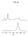
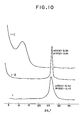
- the thus obtained powder X-ray diffraction pattern is illustrated as a curve 1 in Fig. 9 and a curve 1 in Fig. 10.
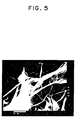
- the decomposition residual carbon was observed under a scanning electron miscroscope.
- a scanning electron microphotograph of the decomposition residual carbon (x 2000 magnification) is shown in Fig. 5.
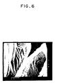
- the decomposition residual carbon was vacuum dried at 400°C for 2 hours.
- a scanning electron microphotography of the dried decomposition residual carbon (x 2000 magnification) is shown in Fig. 6.
- the dried decomposition residual carbon was also subjected to X-ray diffractometry.
- the thus obtained powder X-ray diffraction pattern is illustrated as a curve 1-B in Fig. 10.
- the dried decomposition residual carbon was fluorinated under the reaction conditions as given in Table 3.
- the thus obtained graphite fluorides were subjected to X-ray diffractometry.
- One of the obtained powder X-ray diffraction pattern is illustrated as a curve 1-C in Fig. 10.
- the graphite fluorides obtained by the fluorination at 500°C (F-1) and 400°C (F-3) were observed under a scanning electron microscope. Scanning electron microphotographs of graphite fluorides F-1 and F-3 (x 2000 magnification) are shown in Fig. 7 and Fig. 8, respectively.
- Electrochemical cells were prepared in substantially the same manner as described in Example 1 except that the above obtained graphite fluorides were used as the active material.
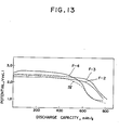
- the discharge characteristics of the obtained electrochemical cells were measured in substantially the same manner as described in Example 1. The results of the measurement are shown in Table 3. Further, the relationships between the discharge capacity (mAh/G) and the potential (V vs Li) are illustrated in Figs. 12 and 13.
- the curves I and II in Fig. 12 respectively show the discharge characteristics of (CF) n obtained in Comparative Example 1 and (C2F),, obtained in Comparative Example 2.
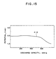
- a graphite fluoride was obtained in substantially the same manner as described in Example 2 except that a decomposition residual carbon was fluorinated at 600°C for 4 hours.
- the thus obtained graphite fluoride was subjected to X-ray diffractometry.
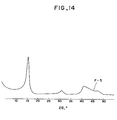
- the obtained X-ray diffraction powder pattern is illustrated as a curve F-5 in Fig. 14.
- the powder X-ray diffraction pattern is substantially the same as that of a conventional (CF) n which will be described later.
- An electrochemical cell was prepared in substantially the same manner as described in Example 1 except that the above obtained graphite fluoride was used as the active material.
- the discharge characteristics of the thus obtained electrochemical cell were measured in substantially the same manner as described in Example 1. The results of the measurement are shown in Table 3. Further, the relationship between the discharge capacity and the potential is shown in Fig. 15.
- An electrochemical cell was prepared in substantially the same manner as described in Example 1 except that(CF) n which had been obtained by directly fluorinating a petroleum coke having a particle size of 10 to 15 11m which had not been subjected to heat treatment was used as the active material.
- the discharge characteristics of the electrochemical cell were measured in substantially the same manner as described in Example 1. The relationship between the discharge capacity and the potential, obtained from the results of the measurement, is illustrated as a curve IV in Fig. 13.
- the flakes were separated from the mixture by using a piece of guaze, and washed with alcohol.
- the thus obtained graphitic oxide was subjected to X-ray diffractometry.
- the obtained powder X-ray diffraction pattern is illustrated as a curve 2 in Fig. 9 and Fig. 11.
- the obtained graphitic oxide was heated up to 400°C at a temperature elevation rate of 0.2°C/min. to effect the thermal decomposition of the graphitic oxide. Further, the thermal decomposition of the graphitic oxide was effected in vacuo at 400°C for 2 hours and subsequently at 500°C for 2 hours. After the thermal decomposition, the obtained decomposition residual carbon was subjected to an X-ray diffractometry.
- the powder X-ray diffraction patterns of a decomposition residual carbon obtained by heating up to 400°C at a temperature elevation rate of 0.2°C/min, a decomposition residual carbon obtained by further heating in vacuo at 400°C for 2 hours and a decomposition residual carbon obtained by still further heating in vacuo at 500°C for 2 hours are illustrated respectively as curves 2-B, 2-C and 2-D in Fig. 11.
- Each of the above-mentioned decomposition residual carbons obtained by heating in vacuo at 500°C for 2 hours was separately fluorinated at 450°C for 2.5 hours, at 400°C for 2.5 hours and at 350°C for 4 hours, respectively.
- each graphite fluoride to be used in the present invention as an active material was obtained.
- the obtained graphite fluoride was subjected to an X-ray diffractometry.
- the obtained powder X-ray diffraction pattern is illustrated as a curve 2-E in Fig. 11. :
- a decomposition residual carbon was obtained.
- the obtained decomposition residual carbon was washed with water and vacuum dried at 400°C for 2 hours.
- the thus obtained decomposition residual carbon was fluorinated in an atmosphere of fluorine at 300°C for 25 hours to obtain a graphite fluoride.
- the thus obtained graphite fluoride was subjected to elementary analysis. As a result, the F/C ratio of the graphite fluoride was found to be 1.19.
- the graphite fluoride was subjected to X-ray diffractometry. The obtained powder X-ray diffraction pattern is shown in Fig. 16.
- An electrochemical cell was prepared in substantially the same manner as described in Example 1 except that the above-obtained graphite fluoride was used as the active material.
- the discharge characteristics of the electrochemical cell was measured in substantially the same manner as described in Example 1. As a result, it was found that the discharge capacity was 870 mAh/g; the OCV, 3.42 V; the CCV, 2.29 V; the overvoltage, 1.13 V; and the energy density, 1730 VAh/kg.
- the discharge capacity, the OCV, the CCV and the overvoltage were measured at a constant-current discharge of 0.5 mAlcm 2.
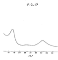
- the obtained decomposition residual carbon was washed with water and vacuum dried at 400°C for 2 hours.
- the thus obtained decomposition residual carbon was fluorinated in an atmosphere of fluorine at 200°C for 17 hours to obtain a graphite fluoride.
- the thus obtained graphite fluoride was subjected to elementary analysis. As a result, the F/C ratio of the graphite fluoride was found to be 1.28.
- the graphite fluoride was subjected to X-ray diffractometry. The obtained powder X-ray diffraction pattern is shown in Fig. 17.
- An electrochemical cell was prepared in substantially the same manner as described in Example 1 except that the above-obtained graphite fluoride was used as the active material.
- the discharge characteristics of the electrochemical cell were measured in substantially the same manner as described in Example 1. As a result, it was found that the discharge capacity was 860 mAh/g; the OCV, 3.36 V; the CCV, 2.30 V; the overvoltage, 1.06 V.
- the discharge capacity, the OCV, the CCV and teh overvoltage were measured at a constant-current discharge of 0.5 mAlcm 2.
- a natural graphite (150 to 200 mesh, Tyler) from Madagascar was fluorinated at 590°C for 27.5 hours to obtain a conventional graphite fluoride (CF) n .
- the thus obtained graphite fluoride (CF) n was subjected to X-ray diffractometry.
- the obtained powder X-ray diffraction pattern is shown in Fig. 18.
- An electrochemical cell was prepared in substantially the same manner as described in Example 1 except that the above-obtained graphite fluoride was used as the active material.
- the discharge characteristics of the obtained electrochemical cell were measured in substantially the same manner as described in Example 1.
- the discharge capacity was 800 mAh/g; the OCV, 3.30 V; the CCV, 1.98 V; and the overvoltage, 1.32 V.
- the discharge capacity, the OCV, the CCV and the overvoltage were measured at a constant-current discharge of 0.5mA/cm 2 . Further, the relationship between the discharge capacity and the potential is shown in Fig. 19.
Landscapes
- Chemical & Material Sciences (AREA)
- Inorganic Chemistry (AREA)
- General Chemical & Material Sciences (AREA)
- Organic Chemistry (AREA)
- Chemical Kinetics & Catalysis (AREA)
- Electrochemistry (AREA)
- Geology (AREA)
- General Life Sciences & Earth Sciences (AREA)
- Environmental & Geological Engineering (AREA)
- Life Sciences & Earth Sciences (AREA)
- Battery Electrode And Active Subsutance (AREA)
- Carbon And Carbon Compounds (AREA)
- Secondary Cells (AREA)
Claims (4)
Applications Claiming Priority (2)
| Application Number | Priority Date | Filing Date | Title |
|---|---|---|---|
| JP59236852A JPH0677458B2 (ja) | 1984-11-12 | 1984-11-12 | 電池活物質 |
| JP236852/84 | 1984-11-12 |
Publications (3)
| Publication Number | Publication Date |
|---|---|
| EP0184679A2 EP0184679A2 (de) | 1986-06-18 |
| EP0184679A3 EP0184679A3 (en) | 1987-09-30 |
| EP0184679B1 true EP0184679B1 (de) | 1990-08-16 |
Family
ID=17006750
Family Applications (1)
| Application Number | Title | Priority Date | Filing Date |
|---|---|---|---|
| EP85114365A Expired - Lifetime EP0184679B1 (de) | 1984-11-12 | 1985-11-12 | Verfahren zur Herstellung eines Graphitfluorids zur Verwendung in einer elektrochemischen Zelle |
Country Status (4)
| Country | Link |
|---|---|
| US (1) | US4753786A (de) |
| EP (1) | EP0184679B1 (de) |
| JP (1) | JPH0677458B2 (de) |
| DE (1) | DE3579222D1 (de) |
Cited By (1)
| Publication number | Priority date | Publication date | Assignee | Title |
|---|---|---|---|---|
| CN108190858A (zh) * | 2017-12-28 | 2018-06-22 | 湖北卓熙氟化股份有限公司 | 一种氟化石墨的制备方法 |
Families Citing this family (30)
| Publication number | Priority date | Publication date | Assignee | Title |
|---|---|---|---|---|
| JPS6313268A (ja) * | 1986-07-04 | 1988-01-20 | Daikin Ind Ltd | 電池活物質 |
| US4957661A (en) * | 1988-09-30 | 1990-09-18 | The United States Of America As Represented By The United States National Aeronautics And Space Administration | Graphite fluoride fiber polymer composite material |
| GB8904431D0 (en) * | 1989-02-27 | 1989-04-12 | Atomic Energy Authority Uk | Cathode material |
| JPH05299100A (ja) * | 1992-04-17 | 1993-11-12 | Matsushita Electric Ind Co Ltd | 有機電解質電池およびそのふっ化カーボン正極の製造法 |
| JPH07161589A (ja) * | 1993-12-06 | 1995-06-23 | Nisshinbo Ind Inc | 電気二重層キャパシタ |
| US5876687A (en) * | 1997-04-04 | 1999-03-02 | The United States Of America As Represented By The Administrator Of The National Aeronautics And Space Administration | Elemental metals or oxides distributed on a carbon substrate or self-supported and the manufacturing process using graphite oxide as template |
| JP3573964B2 (ja) * | 1998-06-17 | 2004-10-06 | 三洋電機株式会社 | アルカリ電池用水素吸蔵合金電極及びアルカリ蓄電池用水素吸蔵合金電極の製造方法 |
| US6713214B2 (en) | 2000-11-13 | 2004-03-30 | Sanyo Electric Co., Ltd. | Positive electrode active material for secondary battery and secondary battery |
| US7358010B2 (en) * | 2002-07-22 | 2008-04-15 | Lodestar Inc. | Fluorinated carbon for metal/fluorinated carbon batteries |
| US20050227146A1 (en) * | 2003-12-12 | 2005-10-13 | Dania Ghantous | Medium rate and high rate batteries |
| WO2005089422A2 (en) * | 2004-03-17 | 2005-09-29 | California Institute Of Technology | Methods for purifying carbon materials |
| GB2419132B (en) * | 2004-10-04 | 2011-01-19 | C Tech Innovation Ltd | Method of production of fluorinated carbon nanostructures |
| US20080300362A1 (en) * | 2005-01-31 | 2008-12-04 | Hua Qiao University | Application And Preparation For The Composite Electrolyte Based On Superabsorbent Hybrid |
| US20070218364A1 (en) * | 2005-10-05 | 2007-09-20 | Whitacre Jay F | Low temperature electrochemical cell |
| US7563542B2 (en) | 2005-10-05 | 2009-07-21 | California Institute Of Technology | Subfluorinated graphite fluorides as electrode materials |
| US20100221603A1 (en) * | 2006-03-03 | 2010-09-02 | Rachid Yazami | Lithium ion fluoride battery |
| US8232007B2 (en) | 2005-10-05 | 2012-07-31 | California Institute Of Technology | Electrochemistry of carbon subfluorides |
| US7794880B2 (en) | 2005-11-16 | 2010-09-14 | California Institute Of Technology | Fluorination of multi-layered carbon nanomaterials |
| US8377586B2 (en) | 2005-10-05 | 2013-02-19 | California Institute Of Technology | Fluoride ion electrochemical cell |
| US7658901B2 (en) * | 2005-10-14 | 2010-02-09 | The Trustees Of Princeton University | Thermally exfoliated graphite oxide |
| US8658309B2 (en) * | 2006-08-11 | 2014-02-25 | California Institute Of Technology | Dissociating agents, formulations and methods providing enhanced solubility of fluorides |
| JP2010521782A (ja) * | 2007-03-14 | 2010-06-24 | カリフォルニア・インスティテュート・オブ・テクノロジー | 高放電率電池 |
| US9029019B2 (en) * | 2007-08-17 | 2015-05-12 | Nanotek Instruments, Inc. | Carbon anode compositions for lithium ion batteries |
| US7993780B2 (en) * | 2007-10-05 | 2011-08-09 | Nanotek Instruments, Inc. | Process for producing carbon anode compositions for lithium ion batteries |
| JP5270906B2 (ja) * | 2007-11-08 | 2013-08-21 | Jx日鉱日石エネルギー株式会社 | リチウムイオン二次電池負極材料用原料炭組成物及びその製造方法 |
| WO2009153051A1 (en) | 2008-06-20 | 2009-12-23 | MAX-PLANCK-Gesellschaft zur Förderung der Wissenschaften e.V. | Use of a superfine expanded graphite and preparation thereof |
| US20100092809A1 (en) * | 2008-10-10 | 2010-04-15 | Board Of Trustees Of Michigan State University | Electrically conductive, optically transparent films of exfoliated graphite nanoparticles and methods of making the same |
| US20100141211A1 (en) * | 2008-11-04 | 2010-06-10 | Rachid Yazami | Hybrid electrochemical generator with a soluble anode |
| JP5971279B2 (ja) * | 2014-05-30 | 2016-08-17 | エス・イー・アイ株式会社 | 電極材料の製造方法 |
| CN110724572A (zh) * | 2018-07-16 | 2020-01-24 | 张家港希弗新能源科技有限公司 | 一种氟化石墨脱模剂的制备方法 |
Family Cites Families (11)
| Publication number | Priority date | Publication date | Assignee | Title |
|---|---|---|---|---|
| BE703624A (de) * | 1966-10-24 | 1968-02-01 | ||
| IT500097A (de) * | 1968-04-12 | |||
| JPS4825566B1 (de) * | 1968-04-17 | 1973-07-30 | ||
| US3922174A (en) * | 1973-01-22 | 1975-11-25 | Gte Laboratories Inc | Electrochemical cell |
| JPS549730A (en) * | 1977-06-24 | 1979-01-24 | Matsushita Electric Industrial Co Ltd | Active material on positive electrode of battery |
| JPS5528246A (en) * | 1978-08-21 | 1980-02-28 | Oyo Kagaku Kenkyusho | Active material for battery |
| JPS5551709A (en) * | 1978-10-13 | 1980-04-15 | Oyo Kagaku Kenkyusho | Production of graphite fluoride |
| GB2106736B (en) * | 1981-09-03 | 1985-06-12 | Standard Telephones Cables Ltd | Optical transmission system |
| JPS5845104A (ja) * | 1981-09-10 | 1983-03-16 | Oyo Kagaku Kenkyusho | (C↓2F)nを主成分とするフツ化黒船の製造方法 |
| JPS5887766A (ja) * | 1981-11-17 | 1983-05-25 | Matsushita Electric Ind Co Ltd | 有機電解質電池の製造法 |
| EP0126701B1 (de) * | 1983-05-19 | 1987-10-14 | Le Carbone-Lorraine S.A. | Graphiteinlagerungsverbindungen mit verbesserter Leistung und elektrochemische Anwendung dieser Verbindungen |
-
1984
- 1984-11-12 JP JP59236852A patent/JPH0677458B2/ja not_active Expired - Lifetime
-
1985
- 1985-11-12 EP EP85114365A patent/EP0184679B1/de not_active Expired - Lifetime
- 1985-11-12 DE DE8585114365T patent/DE3579222D1/de not_active Expired - Lifetime
-
1987
- 1987-02-03 US US07/010,372 patent/US4753786A/en not_active Expired - Fee Related
Cited By (2)
| Publication number | Priority date | Publication date | Assignee | Title |
|---|---|---|---|---|
| CN108190858A (zh) * | 2017-12-28 | 2018-06-22 | 湖北卓熙氟化股份有限公司 | 一种氟化石墨的制备方法 |
| CN108190858B (zh) * | 2017-12-28 | 2021-06-15 | 湖北卓熙氟化股份有限公司 | 一种氟化石墨的制备方法 |
Also Published As
| Publication number | Publication date |
|---|---|
| US4753786A (en) | 1988-06-28 |
| EP0184679A3 (en) | 1987-09-30 |
| JPH0677458B2 (ja) | 1994-09-28 |
| DE3579222D1 (de) | 1990-09-20 |
| JPS61116759A (ja) | 1986-06-04 |
| EP0184679A2 (de) | 1986-06-18 |
Similar Documents
| Publication | Publication Date | Title |
|---|---|---|
| EP0184679B1 (de) | Verfahren zur Herstellung eines Graphitfluorids zur Verwendung in einer elektrochemischen Zelle | |
| CA1121449A (en) | High voltage electrolytic cell with positive electrode mainly polydicarbon monofluoride | |
| US5817436A (en) | Lithium nickel composite oxide preparation process therefor and application thereof | |
| CA2116424C (en) | Carbonaceous electrode material for secondary battery | |
| Watanabe | Two Types of Graphite Fluorides,(CF) n and (C2F) n, and Discharge Characteristics and Mechanisms of Electrodes of (CF) n and (C2F) n in Lithium Batteries | |
| DE69701202T2 (de) | Nichtwässrige Sekundärbatterie und Verfahren zur Herstellung eines activen Materials for eine negative Electrode | |
| US7563542B2 (en) | Subfluorinated graphite fluorides as electrode materials | |
| US6194067B1 (en) | Carbonaceous particles and carbonaceous fibers both coated with boron nitride, and lithium secondary cells produced by using the same as negative active material | |
| US6358649B1 (en) | Carbons containing fluorine, method of preparation thereof and use as electrode material | |
| KR20100107396A (ko) | 비수 전해질 2차 전지용 부극재 및 그것의 제조 방법, 및 리튬 이온 2차 전지 | |
| KR20080095909A (ko) | 카본 서브플루오라이드의 전기화학 | |
| JP4632016B2 (ja) | 非水電解質電池 | |
| EP0726606A1 (de) | Elektrodenmaterial aus Kohlenstoff für Batterie und Verfahren zu seiner Herstellung | |
| EP0690518A1 (de) | Nichtwässrige Sekundärbatterie und Negativelektrode | |
| US6699297B1 (en) | Method for preparing lithium manganate and positive electrode for lithium secondary cell containing the same | |
| JPH0785888A (ja) | リチウム二次電池 | |
| Hamwi et al. | Graphite fluorides prepared at room temperature 2. A very good electrochemical behaviour as cathode material in lithium non-aqueous electrolyte cell | |
| JP3540085B2 (ja) | 電池電極用炭素質材料、その製造方法、電極構造体および電池 | |
| JP2004220898A (ja) | リチウム二次電池用正極活物質及びその製造方法,並びにリチウム二次電池 | |
| EP0119595B1 (de) | Fluorierte Graphite, Verfahren zu deren Herstellung und elektrische Zelle, die diese als Aktivmasse der positiven Elektrode verwendet | |
| RU2848735C1 (ru) | Способ изготовления фосфида галлия и анод натрий-ионного аккумулятора с повышенной плотностью ёмкости на основе фосфида галлия, изготовленного данным способом | |
| Doan et al. | DEVELOPMENT OF Na0. 7Ni0. 6Mn0. 2Co0. 2O2 EMPLOYING SOL-GEL APPROACH AS CATHODE MATERIAL FOR SODIUM ION BATTERIES | |
| JPH1027612A (ja) | リチウムイオン2次電池用負極材 | |
| JPH08241715A (ja) | リチウム二次電池用負極材料およびその製造法およびそれを用いたリチウム二次電池 | |
| JPH0221099B2 (de) |
Legal Events
| Date | Code | Title | Description |
|---|---|---|---|
| PUAI | Public reference made under article 153(3) epc to a published international application that has entered the european phase |
Free format text: ORIGINAL CODE: 0009012 |
|
| AK | Designated contracting states |
Kind code of ref document: A2 Designated state(s): DE FR GB |
|
| PUAL | Search report despatched |
Free format text: ORIGINAL CODE: 0009013 |
|
| AK | Designated contracting states |
Kind code of ref document: A3 Designated state(s): DE FR GB |
|
| 17P | Request for examination filed |
Effective date: 19871010 |
|
| 17Q | First examination report despatched |
Effective date: 19881006 |
|
| GRAA | (expected) grant |
Free format text: ORIGINAL CODE: 0009210 |
|
| AK | Designated contracting states |
Kind code of ref document: B1 Designated state(s): DE FR GB |
|
| REF | Corresponds to: |
Ref document number: 3579222 Country of ref document: DE Date of ref document: 19900920 |
|
| ET | Fr: translation filed | ||
| PLBE | No opposition filed within time limit |
Free format text: ORIGINAL CODE: 0009261 |
|
| STAA | Information on the status of an ep patent application or granted ep patent |
Free format text: STATUS: NO OPPOSITION FILED WITHIN TIME LIMIT |
|
| 26N | No opposition filed | ||
| PGFP | Annual fee paid to national office [announced via postgrant information from national office to epo] |
Ref country code: GB Payment date: 19931004 Year of fee payment: 9 |
|
| PGFP | Annual fee paid to national office [announced via postgrant information from national office to epo] |
Ref country code: FR Payment date: 19940429 Year of fee payment: 10 |
|
| PGFP | Annual fee paid to national office [announced via postgrant information from national office to epo] |
Ref country code: DE Payment date: 19940627 Year of fee payment: 10 |
|
| PG25 | Lapsed in a contracting state [announced via postgrant information from national office to epo] |
Ref country code: GB Effective date: 19941112 |
|
| GBPC | Gb: european patent ceased through non-payment of renewal fee |
Effective date: 19941112 |
|
| PG25 | Lapsed in a contracting state [announced via postgrant information from national office to epo] |
Ref country code: FR Effective date: 19960731 |
|
| PG25 | Lapsed in a contracting state [announced via postgrant information from national office to epo] |
Ref country code: DE Effective date: 19960801 |
|
| REG | Reference to a national code |
Ref country code: FR Ref legal event code: ST |