EP0184524B1 - Maschine zum Verpacken von Waren in einer wärmeschrumpfbaren Folie - Google Patents
Maschine zum Verpacken von Waren in einer wärmeschrumpfbaren Folie Download PDFInfo
- Publication number
- EP0184524B1 EP0184524B1 EP85420200A EP85420200A EP0184524B1 EP 0184524 B1 EP0184524 B1 EP 0184524B1 EP 85420200 A EP85420200 A EP 85420200A EP 85420200 A EP85420200 A EP 85420200A EP 0184524 B1 EP0184524 B1 EP 0184524B1
- Authority
- EP
- European Patent Office
- Prior art keywords
- edge
- film
- welding
- machine
- longitudinal
- Prior art date
- Legal status (The legal status is an assumption and is not a legal conclusion. Google has not performed a legal analysis and makes no representation as to the accuracy of the status listed.)
- Expired
Links
Images


Classifications
-
- B—PERFORMING OPERATIONS; TRANSPORTING
- B65—CONVEYING; PACKING; STORING; HANDLING THIN OR FILAMENTARY MATERIAL
- B65B—MACHINES, APPARATUS OR DEVICES FOR, OR METHODS OF, PACKAGING ARTICLES OR MATERIALS; UNPACKING
- B65B9/00—Enclosing successive articles, or quantities of material, e.g. liquids or semiliquids, in flat, folded, or tubular webs of flexible sheet material; Subdividing filled flexible tubes to form packages
- B65B9/06—Enclosing successive articles, or quantities of material, in a longitudinally-folded web, or in a web folded into a tube about the articles or quantities of material placed upon it
- B65B9/073—Enclosing successive articles, or quantities of material, in a longitudinally-folded web, or in a web folded into a tube about the articles or quantities of material placed upon it the web having intermittent motion
-
- B—PERFORMING OPERATIONS; TRANSPORTING
- B65—CONVEYING; PACKING; STORING; HANDLING THIN OR FILAMENTARY MATERIAL
- B65B—MACHINES, APPARATUS OR DEVICES FOR, OR METHODS OF, PACKAGING ARTICLES OR MATERIALS; UNPACKING
- B65B53/00—Shrinking wrappers, containers, or container covers during or after packaging
- B65B53/02—Shrinking wrappers, containers, or container covers during or after packaging by heat
- B65B53/06—Shrinking wrappers, containers, or container covers during or after packaging by heat supplied by gases, e.g. hot-air jets
- B65B53/066—Mobile frames, hoods, posts or the like
Definitions
- the invention relates to a machine for packaging various products in a shrink film.
- the articulated bell being most generally opaque, during the entire welding and shrinking operation, the product to be packaged is thus hidden from the view of the operator and does not allow this operation to be controlled, especially to intervene if necessary.
- the hot air contained in this bell rises to his face, which is unpleasant.
- it is necessary for each operation to heat the entire internal volume of the bell which therefore constitutes a significant and unnecessary expense.
- the invention overcomes these drawbacks. It targets a packaging machine of the type in question in heat-shrinkable film which is compact, economical to build and operate, allows the product to be viewed throughout the critical shrinkage phase, allows the operator to intervene if takes place during this phase, and finally can be easily implemented even by inexperienced personnel.
- the invention consists in using in the single workstation as a means of retraction, no longer an articulated bell but a heating gantry, also articulated, but which moreover makes it possible to sweep the entire surface of the product to wrap.
- Figures 1 and 2 show in summary perspective view a first embodiment of a machine according to the invention shown in two successive operating phases, respectively open (Figure 1) for the introduction of the product to be packaged, then closed ( Figure 2) for the welding and shrinking operation.
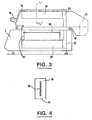
- Figure 3 is a cross-sectional view of another preferred embodiment of the invention.
- Figure 4 is a section along the axis IV-IV '.
- the packaging machine essentially comprises a metal frame (1), carrying at one end a fixed arm (2) intended to receive a reel (3) of a heat-shrinkable film (4), folded in a U (folded ) double thickness (5) and (6), for example polyvinyl chloride.
- a metal frame (1) carrying at one end a fixed arm (2) intended to receive a reel (3) of a heat-shrinkable film (4), folded in a U (folded ) double thickness (5) and (6), for example polyvinyl chloride.
- a transverse pin (7) of separation fixed on one side of the frame (1), so as to move aside in order to receive the product (8) to be packaged.
- the upper part of the frame (1) forms a work table designated by the reference (9).
- This work table (9) is equipped with a lateral longitudinal axis (10) oriented perpendicular to the direction of the transverse pin (7) and parallel to the edge of the table (9).
- a hinged frame (11) is articulated whose internal face of two contiguous sides (12, 13) carries heating resistors, making it possible to weld edge to edge the two sheets (5) and (6) on either side of the object (8) placed on the table (9).
- the folding frame (11) comprises, parallel to and opposite the axis (10), a guide rail (14) in which slides the corresponding lower end (15) of a mobile gantry ( 16).
- the opposite end (17) of the gantry (16) slides by a sleeve (18) along the axis (10).
- the gantry (16) has a control handle (19).
- the mobile gantry (16) arranged parallel and above the table (9) is equipped with a blower (20), connected by a conduit (21) to a hollow arm (22) in which is arranged an electric heating resistor (23).
- This transverse hollow arm (22) is open on the opposite face of the table (9) to thus form a ramp capable of blowing hot air downwards, as indicated by the arrows (24).
- the frame (1) On its front part, the frame (1) also includes a control console (25).
- the operator then lowers the frame (11) ( Figure 2). By acting on the organs of the desk (25), it activates the heating resistors (12, 13) to cause around the book the edge-to-edge welding of the sheets (5) and (6) and thus the cutting.
- the operator acts on the handle (19) to advance the gantry (16) as indicated by the double arrow (26).
- the mobile gantry (16) sweeps the upper space of the table (9) by blowing hot air, as indicated by the arrows (24), in the direction of the book (8) to be packaged. This causes the films welded around the book to shrink (8).
- the machine according to the invention essentially comprises a metal grid (30) intended to form a work table for receiving the product (8) to be packed in the two thicknesses (5) and (6).
- This grid (30) is adjustable in height relative to the mobile gantry, thanks to notches (31) provided for this purpose.
- the mobile gantry (16) is integral with the welding frame (11).
- This mobile retraction gantry essentially consists of a fan (20) arranged at the longitudinal axis (10) parallel to the work table (9), connected by two conduits (32, 33) to two hollow arms ( 34, 35) parallel arranged on either side of the grid (30).
- Each of these two hollow arms (see Figure 4) (34.35) has a heating plate (36) around which the electrical resistance is wound.
- the face of each of these arms opposite the grid (30) has a longitudinal slot (37) intended to receive a distribution and protection grid for the hot air blown by the fan (20) and as indicated by the arrows (24).
- the fan (20) is started automatically when the welding frame (11) is closed, in particular by pressing a contact placed for this purpose on the work table (9).
- the upper arm (35) articulated around the axis (10) comes to coincide by its conduit (33) with the fixed conduit (32) of the fixed lower arm (34).
- the assembly of the two arms respectively fixed (34) and articulated (35) is thus secured. In this way, by sliding the handle (19) in the slide (14) of the frame (11), we move well the entire shrink assembly around the product (8) to be packaged.
- this machine can be advantageously used for packaging various products, such as printing articles: books, magazines, albums, archives, stationery, small mechanical parts, various samples: cosmetics. , toys, food items, etc.
Landscapes
- Engineering & Computer Science (AREA)
- Mechanical Engineering (AREA)
- Containers And Plastic Fillers For Packaging (AREA)
- Auxiliary Devices For And Details Of Packaging Control (AREA)
- Basic Packing Technique (AREA)
Claims (5)
dadurch gekennzeichnet, daß das Mittel zum Schrumpfen durch ein bewegliches Portal (16) gebildet ist, das über dem festen Tisch (9) angeordnet und mit einem Heißluftgebläse (20) versehen ist, dessen Luft gegen den Tisch (9) gerichtet (24) ist, wobei das Mittel zum Schrumpfen dazu geeignet ist, um
Applications Claiming Priority (2)
| Application Number | Priority Date | Filing Date | Title |
|---|---|---|---|
| FR8417992 | 1984-11-15 | ||
| FR8417992A FR2573031B1 (fr) | 1984-11-15 | 1984-11-15 | Machine pour l'emballage de produits divers, sous film thermoretractable |
Publications (2)
| Publication Number | Publication Date |
|---|---|
| EP0184524A1 EP0184524A1 (de) | 1986-06-11 |
| EP0184524B1 true EP0184524B1 (de) | 1988-04-06 |
Family
ID=9309945
Family Applications (1)
| Application Number | Title | Priority Date | Filing Date |
|---|---|---|---|
| EP85420200A Expired EP0184524B1 (de) | 1984-11-15 | 1985-11-08 | Maschine zum Verpacken von Waren in einer wärmeschrumpfbaren Folie |
Country Status (4)
| Country | Link |
|---|---|
| US (1) | US4667456A (de) |
| EP (1) | EP0184524B1 (de) |
| DE (1) | DE3562076D1 (de) |
| FR (1) | FR2573031B1 (de) |
Families Citing this family (6)
| Publication number | Priority date | Publication date | Assignee | Title |
|---|---|---|---|---|
| IT1228435B (it) * | 1987-07-24 | 1991-06-17 | Interdibipack Spa | Apparecchiatura per il confezionamento di un prodotto mediante film di materiale termoretraibile |
| IT241040Y1 (it) * | 1996-12-03 | 2001-04-20 | Minipack Torre Spa | Macchina confezionatrice a film termoretraibile |
| US6266942B1 (en) * | 1998-10-26 | 2001-07-31 | Mcclorey John | Packaging kit for wrapping paper |
| ITMI991602A1 (it) * | 1999-07-21 | 2001-01-21 | Interdibipack Spa | Procedimento e macchina per il confezionamento di prodotti con film termoretraibile monopiega |
| WO2005108213A2 (en) * | 2004-05-05 | 2005-11-17 | Richards John D | Gift wrap cutting system |
| IT202000023344A1 (it) * | 2020-10-05 | 2022-04-05 | Italdibipack Spa | Macchina confezionatrice perfezionata |
Family Cites Families (11)
| Publication number | Priority date | Publication date | Assignee | Title |
|---|---|---|---|---|
| US3047991A (en) * | 1961-05-02 | 1962-08-07 | Weldotron Corp | Impulse sealing apparatus |
| GB974529A (en) * | 1962-11-20 | 1964-11-04 | Smith & Nephew Plastics | Improvements in and relating to packaging machines |
| US3420034A (en) * | 1965-06-25 | 1969-01-07 | Alfred B Saraisky | Wrapping machine |
| US3710550A (en) * | 1970-12-03 | 1973-01-16 | K Osborne | Apparatus for shrinking plastic film over palletized loads |
| US3830036A (en) * | 1973-02-20 | 1974-08-20 | Harkess K D B A Ideanamics | Grocery packaging machine |
| FR2278962A1 (fr) * | 1973-05-25 | 1976-02-13 | Hurdequint Louis | Soufflerie a air chaud destinee, en particulier, a la retraction de films d'emballage |
| US3910011A (en) * | 1973-12-05 | 1975-10-07 | H G Weber And Company Inc | Apparatus for packaging stacked articles |
| IT1024614B (it) * | 1976-03-03 | 1978-07-20 | Torre F | Macchina confezionatrice per il confezionamento di prodotti vari in una pellicola di materiale ternoretraibile |
| BR7604648A (pt) * | 1976-07-16 | 1978-01-31 | G Bartolomei | Aperfeicoamentos em maquinas de embalagem em filme plastico termo-retratil |
| FR2397329A1 (fr) * | 1977-07-12 | 1979-02-09 | Socemim Sa | Machine d'emballage de produits dans une gaine de matiere plastique |
| ATE20015T1 (de) * | 1982-12-30 | 1986-06-15 | Msk Verpackung Syst Gmbh | Verfahren und vorrichtung zum einschrumpfen einer schrumpfhaube, die ueber einen insbesondere palettierten gutstapel gezogen ist. |
-
1984
- 1984-11-15 FR FR8417992A patent/FR2573031B1/fr not_active Expired
-
1985
- 1985-11-08 EP EP85420200A patent/EP0184524B1/de not_active Expired
- 1985-11-08 DE DE8585420200T patent/DE3562076D1/de not_active Expired
- 1985-11-13 US US06/797,617 patent/US4667456A/en not_active Expired - Fee Related
Also Published As
| Publication number | Publication date |
|---|---|
| FR2573031A1 (fr) | 1986-05-16 |
| FR2573031B1 (fr) | 1987-07-03 |
| EP0184524A1 (de) | 1986-06-11 |
| DE3562076D1 (en) | 1988-05-11 |
| US4667456A (en) | 1987-05-26 |
Similar Documents
| Publication | Publication Date | Title |
|---|---|---|
| EP0392933B1 (de) | Verfahren und Vorrichtung zum Schneiden und Schweissen einer Verpackungsfolie | |
| EP0300855B1 (de) | Band mit Längsverstärkung, seine Herstellung und seine Verwendung im Verpackungsverfahren und Vorrichtung zur Herstellung eines solchen Bandes | |
| EP0630812B1 (de) | Einwickel-Maschine | |
| FR2706859A1 (de) | ||
| JPS6160429A (ja) | パツケージ包装機械 | |
| EP0184524B1 (de) | Maschine zum Verpacken von Waren in einer wärmeschrumpfbaren Folie | |
| BRPI0315957B1 (pt) | Aparelho e processo para o acondicionamento de produtos em uma película de plástico estirável | |
| EP0167469B1 (de) | Vorrichtung zum Schweissen und Schneiden mindestens einer Oberecke eines Plastikbeutels | |
| FR2708519A1 (fr) | Dispositif pour le soudage des tronçons de tuyau de sacs, sachets ou analogues. | |
| FR2498557A1 (fr) | Machine a emballer des objets de forme sensiblement cylindrique dans des feuilles decoupees selon un contour ferme dans des bandes d'un materiau souple d'emballage | |
| FR2471916A1 (fr) | Procede et dispositif pour presenter a la canule de remplissage d'une ensacheuse des sacs ouverts a leur partie superieure et pour tasser le contenu des sacs | |
| EP0367881A1 (de) | Falteinrichtung für ein rechteckiges Textilstück | |
| FR2565552A1 (fr) | Procede et appareil pour le conditionnement de certains produits dans des barquettes ou recipients similaires | |
| EP0340093B1 (de) | Aufreissvorrichtung zur Öffnung eines Verpackungsumschlages, bestimmt für ein pastöses Produkt | |
| FR2639611A1 (fr) | Dispositif de pose de coiffe sur une charge emballee par banderolage | |
| EP0334277B1 (de) | Bindemaschine für Stapel von Bögen | |
| EP0697338B1 (de) | Verpackung für ein Produkt nichtspezifischer Form, Satz von Zuschnitten, Verfahren und Vorrichtung zur Herstellung einer solchen Verpackung | |
| FR2460731A1 (fr) | Procede et machine pour fabriquer un element en forme de caisson a partir d'une tole | |
| FR2621010A1 (fr) | Machine pour operculer les barquettes de conditionnement de plats cuisines ou autres similaires | |
| CA2402005A1 (fr) | Derouleuse pour gaine d'emballage equipee de moyens de coupe et de soudage | |
| FR2621888A1 (fr) | Appareil pour l'emballage sous vide de produits dans des sacs souples | |
| WO1991007322A1 (fr) | Machine a botteler et emballer les fleurs | |
| FR2553736A1 (fr) | Machine a emballer des articles quelconques sous film en matiere plastique | |
| FR2861693A1 (fr) | Procede et dispositif de pliage et de conditionnement de matelas | |
| FR2593792A1 (fr) | Distributeur d'elements minces et souples empiles, muni d'un dispositif d'extraction de ces derniers, et boite-cartouche destinee a equiper un tel distributeur |
Legal Events
| Date | Code | Title | Description |
|---|---|---|---|
| PUAI | Public reference made under article 153(3) epc to a published international application that has entered the european phase |
Free format text: ORIGINAL CODE: 0009012 |
|
| AK | Designated contracting states |
Kind code of ref document: A1 Designated state(s): BE CH DE FR GB IT LI |
|
| 17P | Request for examination filed |
Effective date: 19861018 |
|
| 17Q | First examination report despatched |
Effective date: 19870807 |
|
| GRAA | (expected) grant |
Free format text: ORIGINAL CODE: 0009210 |
|
| AK | Designated contracting states |
Kind code of ref document: B1 Designated state(s): BE CH DE FR GB IT LI |
|
| PG25 | Lapsed in a contracting state [announced via postgrant information from national office to epo] |
Ref country code: IT Free format text: LAPSE BECAUSE OF FAILURE TO SUBMIT A TRANSLATION OF THE DESCRIPTION OR TO PAY THE FEE WITHIN THE PRESCRIBED TIME-LIMIT;WARNING: LAPSES OF ITALIAN PATENTS WITH EFFECTIVE DATE BEFORE 2007 MAY HAVE OCCURRED AT ANY TIME BEFORE 2007. THE CORRECT EFFECTIVE DATE MAY BE DIFFERENT FROM THE ONE RECORDED. Effective date: 19880406 |
|
| GBT | Gb: translation of ep patent filed (gb section 77(6)(a)/1977) | ||
| REF | Corresponds to: |
Ref document number: 3562076 Country of ref document: DE Date of ref document: 19880511 |
|
| PG25 | Lapsed in a contracting state [announced via postgrant information from national office to epo] |
Ref country code: LI Effective date: 19881130 Ref country code: CH Effective date: 19881130 |
|
| PLBE | No opposition filed within time limit |
Free format text: ORIGINAL CODE: 0009261 |
|
| STAA | Information on the status of an ep patent application or granted ep patent |
Free format text: STATUS: NO OPPOSITION FILED WITHIN TIME LIMIT |
|
| 26N | No opposition filed | ||
| PG25 | Lapsed in a contracting state [announced via postgrant information from national office to epo] |
Ref country code: FR Free format text: LAPSE BECAUSE OF NON-PAYMENT OF DUE FEES Effective date: 19890731 |
|
| REG | Reference to a national code |
Ref country code: CH Ref legal event code: PL |
|
| REG | Reference to a national code |
Ref country code: FR Ref legal event code: ST |
|
| PGFP | Annual fee paid to national office [announced via postgrant information from national office to epo] |
Ref country code: DE Payment date: 19951123 Year of fee payment: 11 |
|
| PGFP | Annual fee paid to national office [announced via postgrant information from national office to epo] |
Ref country code: BE Payment date: 19961212 Year of fee payment: 12 |
|
| PG25 | Lapsed in a contracting state [announced via postgrant information from national office to epo] |
Ref country code: DE Effective date: 19970801 |
|
| PGFP | Annual fee paid to national office [announced via postgrant information from national office to epo] |
Ref country code: GB Payment date: 19971031 Year of fee payment: 13 |
|
| PG25 | Lapsed in a contracting state [announced via postgrant information from national office to epo] |
Ref country code: BE Free format text: LAPSE BECAUSE OF NON-PAYMENT OF DUE FEES Effective date: 19971130 |
|
| BERE | Be: lapsed |
Owner name: RAFFAULT GERARD Effective date: 19971130 |
|
| PG25 | Lapsed in a contracting state [announced via postgrant information from national office to epo] |
Ref country code: GB Free format text: LAPSE BECAUSE OF NON-PAYMENT OF DUE FEES Effective date: 19981108 |
|
| GBPC | Gb: european patent ceased through non-payment of renewal fee |
Effective date: 19981108 |