EP0184524B1 - Machine for packaging products in a heat-shrinkable film - Google Patents
Machine for packaging products in a heat-shrinkable film Download PDFInfo
- Publication number
- EP0184524B1 EP0184524B1 EP85420200A EP85420200A EP0184524B1 EP 0184524 B1 EP0184524 B1 EP 0184524B1 EP 85420200 A EP85420200 A EP 85420200A EP 85420200 A EP85420200 A EP 85420200A EP 0184524 B1 EP0184524 B1 EP 0184524B1
- Authority
- EP
- European Patent Office
- Prior art keywords
- edge
- film
- welding
- machine
- longitudinal
- Prior art date
- Legal status (The legal status is an assumption and is not a legal conclusion. Google has not performed a legal analysis and makes no representation as to the accuracy of the status listed.)
- Expired
Links
Images


Classifications
-
- B—PERFORMING OPERATIONS; TRANSPORTING
- B65—CONVEYING; PACKING; STORING; HANDLING THIN OR FILAMENTARY MATERIAL
- B65B—MACHINES, APPARATUS OR DEVICES FOR, OR METHODS OF, PACKAGING ARTICLES OR MATERIALS; UNPACKING
- B65B9/00—Enclosing successive articles, or quantities of material, e.g. liquids or semiliquids, in flat, folded, or tubular webs of flexible sheet material; Subdividing filled flexible tubes to form packages
- B65B9/06—Enclosing successive articles, or quantities of material, in a longitudinally-folded web, or in a web folded into a tube about the articles or quantities of material placed upon it
- B65B9/073—Enclosing successive articles, or quantities of material, in a longitudinally-folded web, or in a web folded into a tube about the articles or quantities of material placed upon it the web having intermittent motion
-
- B—PERFORMING OPERATIONS; TRANSPORTING
- B65—CONVEYING; PACKING; STORING; HANDLING THIN OR FILAMENTARY MATERIAL
- B65B—MACHINES, APPARATUS OR DEVICES FOR, OR METHODS OF, PACKAGING ARTICLES OR MATERIALS; UNPACKING
- B65B53/00—Shrinking wrappers, containers, or container covers during or after packaging
- B65B53/02—Shrinking wrappers, containers, or container covers during or after packaging by heat
- B65B53/06—Shrinking wrappers, containers, or container covers during or after packaging by heat supplied by gases, e.g. hot-air jets
- B65B53/066—Mobile frames, hoods, posts or the like
Definitions
- the invention relates to a machine for packaging various products in a shrink film.
- the articulated bell being most generally opaque, during the entire welding and shrinking operation, the product to be packaged is thus hidden from the view of the operator and does not allow this operation to be controlled, especially to intervene if necessary.
- the hot air contained in this bell rises to his face, which is unpleasant.
- it is necessary for each operation to heat the entire internal volume of the bell which therefore constitutes a significant and unnecessary expense.
- the invention overcomes these drawbacks. It targets a packaging machine of the type in question in heat-shrinkable film which is compact, economical to build and operate, allows the product to be viewed throughout the critical shrinkage phase, allows the operator to intervene if takes place during this phase, and finally can be easily implemented even by inexperienced personnel.
- the invention consists in using in the single workstation as a means of retraction, no longer an articulated bell but a heating gantry, also articulated, but which moreover makes it possible to sweep the entire surface of the product to wrap.
- Figures 1 and 2 show in summary perspective view a first embodiment of a machine according to the invention shown in two successive operating phases, respectively open (Figure 1) for the introduction of the product to be packaged, then closed ( Figure 2) for the welding and shrinking operation.
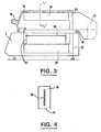
- Figure 3 is a cross-sectional view of another preferred embodiment of the invention.
- Figure 4 is a section along the axis IV-IV '.
- the packaging machine essentially comprises a metal frame (1), carrying at one end a fixed arm (2) intended to receive a reel (3) of a heat-shrinkable film (4), folded in a U (folded ) double thickness (5) and (6), for example polyvinyl chloride.
- a metal frame (1) carrying at one end a fixed arm (2) intended to receive a reel (3) of a heat-shrinkable film (4), folded in a U (folded ) double thickness (5) and (6), for example polyvinyl chloride.
- a transverse pin (7) of separation fixed on one side of the frame (1), so as to move aside in order to receive the product (8) to be packaged.
- the upper part of the frame (1) forms a work table designated by the reference (9).
- This work table (9) is equipped with a lateral longitudinal axis (10) oriented perpendicular to the direction of the transverse pin (7) and parallel to the edge of the table (9).
- a hinged frame (11) is articulated whose internal face of two contiguous sides (12, 13) carries heating resistors, making it possible to weld edge to edge the two sheets (5) and (6) on either side of the object (8) placed on the table (9).
- the folding frame (11) comprises, parallel to and opposite the axis (10), a guide rail (14) in which slides the corresponding lower end (15) of a mobile gantry ( 16).
- the opposite end (17) of the gantry (16) slides by a sleeve (18) along the axis (10).
- the gantry (16) has a control handle (19).
- the mobile gantry (16) arranged parallel and above the table (9) is equipped with a blower (20), connected by a conduit (21) to a hollow arm (22) in which is arranged an electric heating resistor (23).
- This transverse hollow arm (22) is open on the opposite face of the table (9) to thus form a ramp capable of blowing hot air downwards, as indicated by the arrows (24).
- the frame (1) On its front part, the frame (1) also includes a control console (25).
- the operator then lowers the frame (11) ( Figure 2). By acting on the organs of the desk (25), it activates the heating resistors (12, 13) to cause around the book the edge-to-edge welding of the sheets (5) and (6) and thus the cutting.
- the operator acts on the handle (19) to advance the gantry (16) as indicated by the double arrow (26).
- the mobile gantry (16) sweeps the upper space of the table (9) by blowing hot air, as indicated by the arrows (24), in the direction of the book (8) to be packaged. This causes the films welded around the book to shrink (8).
- the machine according to the invention essentially comprises a metal grid (30) intended to form a work table for receiving the product (8) to be packed in the two thicknesses (5) and (6).
- This grid (30) is adjustable in height relative to the mobile gantry, thanks to notches (31) provided for this purpose.
- the mobile gantry (16) is integral with the welding frame (11).
- This mobile retraction gantry essentially consists of a fan (20) arranged at the longitudinal axis (10) parallel to the work table (9), connected by two conduits (32, 33) to two hollow arms ( 34, 35) parallel arranged on either side of the grid (30).
- Each of these two hollow arms (see Figure 4) (34.35) has a heating plate (36) around which the electrical resistance is wound.
- the face of each of these arms opposite the grid (30) has a longitudinal slot (37) intended to receive a distribution and protection grid for the hot air blown by the fan (20) and as indicated by the arrows (24).
- the fan (20) is started automatically when the welding frame (11) is closed, in particular by pressing a contact placed for this purpose on the work table (9).
- the upper arm (35) articulated around the axis (10) comes to coincide by its conduit (33) with the fixed conduit (32) of the fixed lower arm (34).
- the assembly of the two arms respectively fixed (34) and articulated (35) is thus secured. In this way, by sliding the handle (19) in the slide (14) of the frame (11), we move well the entire shrink assembly around the product (8) to be packaged.
- this machine can be advantageously used for packaging various products, such as printing articles: books, magazines, albums, archives, stationery, small mechanical parts, various samples: cosmetics. , toys, food items, etc.
Description
L'invention concerne une machine pour emballer des produits divers sous film thermorétractable.The invention relates to a machine for packaging various products in a shrink film.
Il est bien connu d'emballer des produits divers tels que des produits alimentaires, des articles d'imprimerie ou de papèterie ou des pièces mécaniques dans des films thermorétractables, soudés sur leurs bords.It is well known to package various products such as food products, printing or stationery items or mechanical parts in heat-shrinkable films, welded on their edges.
Une machine du type en question comprend essentiellement:
- - une bobine de film dossé à double épaisseur,
- - un moyen, tel qu'une épingle ou analogue, pour écarter les deux épaisseurs de ce film et disposer entre celles-ci le produit à emballer,
- - un poste de soudure où l'on soude bord à bord la périphérie des deux épaisseurs du film autour du produit à emballer;
- - un poste de rétraction où l'ensemble est soumis à un traitement thermique provoquant la rétraction du film autour du produit dont il épouse ainsi les formes.
- - a roll of double-layered film,
- a means, such as a pin or the like, for separating the two thicknesses of this film and placing the product to be packaged between them,
- - a welding station where the periphery of the two thicknesses of film is welded edge to edge around the product to be packaged;
- - a shrinking station where the assembly is subjected to a heat treatment causing the shrinkage of the film around the product of which it thus follows the shapes.
Dans les brevets américains US-A-4 104 848 et 4162 604, on a proposé une machine du type en question dans laquelle le poste de soudure et le poste de rétraction sont groupés en un seul poste de travail. Ce poste unique de travail comprend essentiellement:
- - une table fixe de travail perforée destinée à recevoir le produit dans son emballage à rétracter;
- - une cloche, articulée autour d'un des bords de la table de travail et dont deux bords adjacents formant un L comportent des résistances électriques de soudure;
- - un dispositif de chauffage, associé à un ventilateur, disposé de l'autre côté de la table de travail perforée.
- - a fixed perforated work table intended to receive the product in its packaging to be retracted;
- - a bell, articulated around one of the edges of the work table and two adjacent edges of which form an L include electrical welding resistors;
- - a heating device, associated with a fan, arranged on the other side of the perforated work table.
Dans cette disposition assez encombrante, la cloche articulée étant le plus généralement opaque, pendant toute l'opération de soudure et de rétraction, le produit à emballer se trouve ainsi caché à la vue de l'opérateur et ne permet pas de contrôler cette opération, notamment d'intervenir s'il y a lieu. En outre, lorsque l'opérateur soulève la cloche articulée, une fois l'opération terminée, l'air chaud contenu dans cette cloche lui monte au visage, ce qui est désagréable. Enfin, quelque soient les dimensions du produit à emballer, il est nécessaire à chaque opération de chauffer tout le volume interne de la cloche, ce qui constitue donc une dépense importante et inutile.In this rather bulky arrangement, the articulated bell being most generally opaque, during the entire welding and shrinking operation, the product to be packaged is thus hidden from the view of the operator and does not allow this operation to be controlled, especially to intervene if necessary. In addition, when the operator raises the articulated bell, once the operation is finished, the hot air contained in this bell rises to his face, which is unpleasant. Finally, whatever the dimensions of the product to be packaged, it is necessary for each operation to heat the entire internal volume of the bell, which therefore constitutes a significant and unnecessary expense.
L'invention pallie ces inconvénients. Elle vise une machine à emballer du type en question sous film thermorétractable qui soit peu encombrante, économique à construire et à faire fonctionner, permette de visualiser le produit pendant toute la phase critique de rétraction, permette à l'opérateur d'intervenir s'il y a lieu pendant cette phase, et enfin puisse être facilement mise en oeuvre même par du personnel non expérimenté.The invention overcomes these drawbacks. It targets a packaging machine of the type in question in heat-shrinkable film which is compact, economical to build and operate, allows the product to be viewed throughout the critical shrinkage phase, allows the operator to intervene if takes place during this phase, and finally can be easily implemented even by inexperienced personnel.
Cette machine perfectionnée pour emballer des produits sous film thermorétractable, du type comprenant:
- . une bobine d'alimentation pour un film plié, souple, à double épaisseur, destiné à emballer un produit,
- . des moyens pour écarter les deux épaisseurs de ce film,
- . des moyens pour souder en périphérie le film bord à bord, lesdits moyens de soudage étant constitués par un cadre dont deux côtés contigus en forme de L comportent des résistances électriques chauffantes, ledit cadre étant relevable autour de l'axe longitudinal parallèle à la table,
- . des moyens pour rétracter le film autour du produit à emballer,
dans laquelle les moyens de soudage et de rétraction sont groupés en un seul poste de travail sur une table fixe,
se caractérise en ce que le moyen de rétraction est constitué par un portque mobile disposé au dessus de la table fixe, ledit portique étant equipé d'une source d'air chaud dirigé vers la table, et étant susceptible: - - d'une part, de coulisser horizontalement le long de la table fixe pour balayer la surface du produit à rétracter après soudage bord à bord;
- - et d'autre part, de pivoter dans un plan orthogonal par rapport au plan de la table.
- . a supply reel for a folded, flexible, double-thickness film intended for packaging a product,
- . means to separate the two thicknesses of this film,
- . means for edge-to-edge welding of the film, said welding means being constituted by a frame, two contiguous L-shaped sides of which include electric heating resistors, said frame being liftable around the longitudinal axis parallel to the table,
- . means for shrinking the film around the product to be packaged,
in which the welding and shrinking means are grouped in a single work station on a fixed table,
is characterized in that the retraction means is constituted by a movable portque disposed above the fixed table, said gantry being equipped with a source of hot air directed towards the table, and being susceptible: - - On the one hand, to slide horizontally along the fixed table to sweep the surface of the product to be shrunk after welding edge to edge;
- - And secondly, to rotate in a plane orthogonal to the plane of the table.
En d'autres termes, l'invention consiste à utiliser dans le poste de travail unique comme moyen de rétraction, non plus une cloche articulée mais un portique chauffant, également articulé, mais qui en outre, permet de balayer toute la surface du produit à emballer.In other words, the invention consists in using in the single workstation as a means of retraction, no longer an articulated bell but a heating gantry, also articulated, but which moreover makes it possible to sweep the entire surface of the product to wrap.
Avantageusement, en pratique:
- - le portique mobile comprend:
- . un bras transversal creux, ouvert sur la face en regard de la table, articulé autour et le long d'un axe longitudinal parallèle au bord de la table, ledit bras creux étant relié à un ventilateur soufflant de l'air sur des résistances chauffantes placées dans ledit bras creux,
- . et une poignée de manoeuvre placée à l'extrémité du bras creux opposée à celle recevant l'axe d'articulation, destinée à permettre l'actionnement de ce bras le long et autour de cet axe;
- - ledit axe longitudinal parallèle à la table sert de guidage à léxtrémité du portique mobile relevable, tandis que l'extrémité opposée de ce portique est guidée dans une glissière longitudinale prévue à cet effet dans le cadre;
- - la table de travail est constituée par une brille métallique réglable en hauteur par rapport au portique mobile ; - le portique mobile de rétraction, coulissable et relevable le long de l'axe longitudinal parallèle à la table, solidaire du cadre de soudure,
- comprend:
- . un ventilateur,
- . deux bras transversaux creux parallèles, disposés de part et d'autre de la table grillagée, chaque bras comportant:
- x un conduit pour le relier au ventilateur,
- x une résistance électrique chauffante,
- x une fente longitudinale disposée en regard de la grille de travail, destinée à diriger l'air chaud soufflé sur les films soudés a rétracter, disposés autour du produit à emballer,
- x une poignée de manoeuvre, fixée à l'extrémité du bras supérieur, destinée, après soudure bord à bord des deux épaisseurs du film, à permettre le coulissement longitudinal du portique mobile le long et autour de cet axe longitudinal parallèle à la table de travail.
- - the mobile gantry includes:
- . a hollow transverse arm, open on the opposite face of the table, articulated around and along a longitudinal axis parallel to the edge of the table, said hollow arm being connected to a fan blowing air on heating resistors placed in said hollow arm,
- . and an operating handle placed at the end of the hollow arm opposite to that receiving the articulation axis, intended to allow the actuation of this arm along and around this axis;
- - Said longitudinal axis parallel to the table serves as a guide at the end of the lifting mobile gantry, while the opposite end of this gantry is guided in a longitudinal slide provided for this purpose in the frame;
- - the work table is constituted by a metallic shine adjustable in height with respect to the mobile gantry; - the mobile retraction gantry, sliding and lifting along the longitudinal axis parallel to the table, integral with the welding frame,
- includes:
- . a fan,
- . two parallel hollow transverse arms, arranged on either side of the mesh table, each arm comprising:
- x a duct to connect it to the fan,
- x an electric heating resistance,
- x a longitudinal slot arranged opposite the working grid, intended to direct the hot air blown onto the shrink-welded films, arranged around the product to be packaged,
- x an operating handle, fixed to the end of the upper arm, intended, after edge-to-edge welding of the two thicknesses of the film, to allow the longitudinal sliding of the mobile gantry along and around this longitudinal axis parallel to the work table .
La manière dont l'invention peut être réalisée et les avantages qui en découlent ressortiront mieux des exemples de réalisation qui suivent donnés à titre indicatif et non limitatif.The manner in which the invention can be implemented and the advantages which ensue therefrom will emerge more clearly from the exemplary embodiments which follow, given by way of indication and without limitation.
Les figures 1 et 2 montrent en vue perspective sommaire une première forme de réalisation d'une machine conforme à l'invention représentée dans deux phases successives de fonctionnement, respectivement ouverte (figure 1) pour la mise en place du produit à emballer, puis fermée (figure 2) pour l'opération de soudure et de rétraction.Figures 1 and 2 show in summary perspective view a first embodiment of a machine according to the invention shown in two successive operating phases, respectively open (Figure 1) for the introduction of the product to be packaged, then closed (Figure 2) for the welding and shrinking operation.
La figure 3 est une vue en coupe transversale d'une autre forme de réalisation préférée de l'invention.Figure 3 is a cross-sectional view of another preferred embodiment of the invention.
La figure 4 est une section selon l'axe IV-IV'.Figure 4 is a section along the axis IV-IV '.
La machine pour emballer conforme à l'invention comprend essentiellement un bâti (1) métallique, portant à une extrémité un bras fixe (2) destiné à recevoir une bobine (3) d'un film (4) thermorétractable, replié en U (dossé) à double épaisseur (5) et (6), par exemple en polychlorure de vinyle. En se déroulant, les deux épaisseurs (5) et (6) du film (4) passent respectivement au dessous et au dessus d'une épingle transversale (7) de séparation fixée sur un côté du bâti (1), de manière à les écarter afin de recevoir le produit (8) à emballer. La partie supérieure du bâti (1) forme une table de travail désignée par la référence (9). Cette table de travail (9) est équipée d'une axe longitudinal latéral (10) orienté perpendiculairement à la direction de l'épingle transversale (7) et parallèlement au bord de la table (9). Sur cet axe longitudinal (10), est articulé un cadre rabattable (11) dont la face interne de deux côtés contigus (12, 13) porte des résistances chauffantes, permettant de souder bord à bord les deux feuilles (5) et (6) de part et d'autre de l'objet (8) posé sur la table (9).The packaging machine according to the invention essentially comprises a metal frame (1), carrying at one end a fixed arm (2) intended to receive a reel (3) of a heat-shrinkable film (4), folded in a U (folded ) double thickness (5) and (6), for example polyvinyl chloride. By unwinding, the two thicknesses (5) and (6) of the film (4) pass respectively below and above a transverse pin (7) of separation fixed on one side of the frame (1), so as to move aside in order to receive the product (8) to be packaged. The upper part of the frame (1) forms a work table designated by the reference (9). This work table (9) is equipped with a lateral longitudinal axis (10) oriented perpendicular to the direction of the transverse pin (7) and parallel to the edge of the table (9). On this longitudinal axis (10), a hinged frame (11) is articulated whose internal face of two contiguous sides (12, 13) carries heating resistors, making it possible to weld edge to edge the two sheets (5) and (6) on either side of the object (8) placed on the table (9).
Le cadre rabattable (11) comporte, parallèlement à l'axe (10) et à l'opposé de celui- ci, un rail de guidage (14) dans lequel coulisse l'extrémité inférieure (15) correspondante d'un portique mobile (16). L'extrémité opposée (17) du portique (16), coulisse, par un manchon (18), le long de l'axe (10).The folding frame (11) comprises, parallel to and opposite the axis (10), a guide rail (14) in which slides the corresponding lower end (15) of a mobile gantry ( 16). The opposite end (17) of the gantry (16) slides by a sleeve (18) along the axis (10).
A proximité de la glissière (14), le portique (16) comporte une poignée de commande (19).Near the slide (14), the gantry (16) has a control handle (19).
Selon les caractéristiques de l'invention, le portique mobile (16) disposé parallèlement et au dessus de la table (9) est équipé d'une soufflerie (20), reliée par un conduit (21) à un bras creux (22) dans lequel est disposée une résistance électrique chauffante (23). Ce bras creux transversal (22) est ouvert sur la face en regard de la table (9) pour constituer ainsi une rampe susceptible de souffler de l'air chaud vers le bas, comme indiqué par les flèches (24).According to the characteristics of the invention, the mobile gantry (16) arranged parallel and above the table (9) is equipped with a blower (20), connected by a conduit (21) to a hollow arm (22) in which is arranged an electric heating resistor (23). This transverse hollow arm (22) is open on the opposite face of the table (9) to thus form a ramp capable of blowing hot air downwards, as indicated by the arrows (24).
Sur sa partie avant, le bâti (1) comporte également un pupitre de commande (25).On its front part, the frame (1) also includes a control console (25).
Pour emballer un produit tel que par exemple un livre (8), l'opérateur soulève le cadre (11) (figure 1). Il tire jusqu'au dessus du plateau de travail (9) une longueur des deux épaisseurs (5) et (6) et place le livré (8) entre ces deux épaisseurs, l'ensemble reposant sur la table (9).To pack a product such as for example a book (8), the operator raises the frame (11) (Figure 1). He pulls a length of the two thicknesses (5) and (6) to the top of the work plate (9) and places the delivery (8) between these two thicknesses, the assembly resting on the table (9).
L'opérateur abaisse ensuite le cadre (11) (figure 2). Par action sur les organes du pupitre (25), il actionne les résistances chauffantes (12, 13) pour provoquer autour du livre la soudure bord à bord des feuilles (5) et (6) et ainsi la découpe. Aussitôt après, et sans avoir à déplacer le cadre (11), l'opérateur agit sur la poignée (19) pour faire avancer le portique (16) comme indiqué par la flèche double (26). Ainsi, le portique mobile (16) balaie l'espace supérieur de la table (9) en soufflant de l'air chaud, comme indiqué par les flèches (24), dans la direction du livre (8) à emballer. Cela provoque la rétraction des films soudés autour du livre (8).The operator then lowers the frame (11) (Figure 2). By acting on the organs of the desk (25), it activates the heating resistors (12, 13) to cause around the book the edge-to-edge welding of the sheets (5) and (6) and thus the cutting. Immediately after, and without having to move the frame (11), the operator acts on the handle (19) to advance the gantry (16) as indicated by the double arrow (26). Thus, the mobile gantry (16) sweeps the upper space of the table (9) by blowing hot air, as indicated by the arrows (24), in the direction of the book (8) to be packaged. This causes the films welded around the book to shrink (8).
Lorsqu'il relève le cadre (11), l'opérateur n'a plus qu'à saisir ce livre (8) dûment emballé.When he raises the frame (11), the operator only has to grab this book (8) duly packaged.
Dans la forme de réalisation préférée montrée aux figures 3 et 4, la machine selon l'invention comprend essentiellement une grille métallique (30) destinée à former table de travail pour recevoir le produit (8) à emballer dans les deux épaisseurs (5) et (6). Cette grille (30) est réglable en hauteur par rapport au portique mobile chauffant, grâce à des encoches (31) prévues à cet effet. Comme dans la forme de réalisation précédente, le portique mobile (16) est solidaire du cadre de soudure (11). Ce portique mobile de rétraction se compose essentiellement d'un ventilateur (20) disposé au niveau de l'axe longitudinal (10) parallèle à la table de travail (9), relié par deux conduits (32, 33) à deux bras creux (34, 35) parallèles disposés de part et d'autre de la grille (30). Chacun de ces deux bras creux (voir figure 4) (34.35) comporte une plaque de chauffe (36) autour de laquelle est enroulée la résistance électrique. La face de chacun de ces bras en regard de la grille (30) présente une fente (37) longitudinale destinée à recevoir une grille de répartition et de protection pour l'air chaud pulsé par le ventilateur (20) et comme indiqué par les flèches (24). La mise en route du ventilateur (20) s'effectue automatiquement lors de la fermeture du cadre (11) de soudure, notamment par appui sur un contact placé à cet effet sur la table de travail (9). De même, pendant cette opération de fermeture, le bras supérieur (35) articulé autour de l'axe (10) vient coïncider par son conduit (33) avec le conduit fixe (32) du bras inférieur fixe (34). L'ensemble des deux bras respectivement fixe (34) et articulé (35) se trouve ainsi solidarisé. De la sorte, en faisant coulisser la poignée (19) dans la glissière (14) du cadre (11), on déplace bien tout l'ensemble de rétraction autour du produit (8) à emballer.In the preferred embodiment shown in FIGS. 3 and 4, the machine according to the invention essentially comprises a metal grid (30) intended to form a work table for receiving the product (8) to be packed in the two thicknesses (5) and (6). This grid (30) is adjustable in height relative to the mobile gantry, thanks to notches (31) provided for this purpose. As in the previous embodiment, the mobile gantry (16) is integral with the welding frame (11). This mobile retraction gantry essentially consists of a fan (20) arranged at the longitudinal axis (10) parallel to the work table (9), connected by two conduits (32, 33) to two hollow arms ( 34, 35) parallel arranged on either side of the grid (30). Each of these two hollow arms (see Figure 4) (34.35) has a heating plate (36) around which the electrical resistance is wound. The face of each of these arms opposite the grid (30) has a longitudinal slot (37) intended to receive a distribution and protection grid for the hot air blown by the fan (20) and as indicated by the arrows (24). The fan (20) is started automatically when the welding frame (11) is closed, in particular by pressing a contact placed for this purpose on the work table (9). Similarly, during this closing operation, the upper arm (35) articulated around the axis (10) comes to coincide by its conduit (33) with the fixed conduit (32) of the fixed lower arm (34). The assembly of the two arms respectively fixed (34) and articulated (35) is thus secured. In this way, by sliding the handle (19) in the slide (14) of the frame (11), we move well the entire shrink assembly around the product (8) to be packaged.
Ainsi, toutes les opérations de soudure et de retraction sont effectuées non seulement sur un seul poste de travail, mais entièrement sous les yeux de l'opérateur, ce qui permet ainsi une maîtrise complète de cette opération.Thus, all the welding and shrinking operations are carried out not only on a single workstation, but entirely under the eyes of the operator, which thus allows complete control of this operation.
Le dispositif selon l'invention présente de nombreux avantages par rapport aux solutions connues, notamment celles citées dans le préambule. On peut citer:
- - un encombrement réduit;
- - la possibilité d'être mis en oeuvre par un personnel non qualifié et non expérimenté;
- - une grande souplesse de manipulation;
- - le fait que pendant toute l'opération, les produits à emballer restent visibles, ce qui permet à l'opérateur s'il y a lieu d'intervenir;
- - l'absence de désagréments pour l'opérateur qui ne reçoit plus au visage une bouffée d'air chaud;
- - la simplicité de construction et de mise en oeuvre;
- - la possibilité d'emballer des petits paquets, puis seulement ensuite d'effectuer la rétraction de ces paquets groupés sur la même table de travail, ce qui permet ainsi d'augmenter les cadences et de diminuer le prix de revient.
- - reduced dimensions;
- - the possibility of being implemented by unqualified and inexperienced personnel;
- - great flexibility of handling;
- - the fact that during the entire operation, the products to be packaged remain visible, which allows the operator to intervene;
- - the absence of inconvenience for the operator who no longer receives a breath of hot air in the face;
- - the simplicity of construction and implementation;
- - the possibility of packing small packages, then only then to carry out the retraction of these packages grouped on the same work table, which thus makes it possible to increase the rates and reduce the cost price.
De la sorte, cette machine peut être utilisée avantageusement pour l'emballage des produits divers, tels que des articles d'imprimerie: livres, magazines, albums, des archives, des articles de papèterie, des petites pièces mécaniques, des échantillons divers: cosmétiques, jouets, des articles alimentaires, etc..In this way, this machine can be advantageously used for packaging various products, such as printing articles: books, magazines, albums, archives, stationery, small mechanical parts, various samples: cosmetics. , toys, food items, etc.
Claims (5)
wherein the retraction means includes a movable crane (16) disposed above the fixed table (9), and is equipped with a source of hot air (20), directed (24) towards the table (9), and is able:
Applications Claiming Priority (2)
| Application Number | Priority Date | Filing Date | Title |
|---|---|---|---|
| FR8417992A FR2573031B1 (en) | 1984-11-15 | 1984-11-15 | MACHINE FOR PACKAGING VARIOUS PRODUCTS, UNDER HEAT SHRINK FILM |
| FR8417992 | 1984-11-15 |
Publications (2)
| Publication Number | Publication Date |
|---|---|
| EP0184524A1 EP0184524A1 (en) | 1986-06-11 |
| EP0184524B1 true EP0184524B1 (en) | 1988-04-06 |
Family
ID=9309945
Family Applications (1)
| Application Number | Title | Priority Date | Filing Date |
|---|---|---|---|
| EP85420200A Expired EP0184524B1 (en) | 1984-11-15 | 1985-11-08 | Machine for packaging products in a heat-shrinkable film |
Country Status (4)
| Country | Link |
|---|---|
| US (1) | US4667456A (en) |
| EP (1) | EP0184524B1 (en) |
| DE (1) | DE3562076D1 (en) |
| FR (1) | FR2573031B1 (en) |
Families Citing this family (6)
| Publication number | Priority date | Publication date | Assignee | Title |
|---|---|---|---|---|
| IT1228435B (en) * | 1987-07-24 | 1991-06-17 | Interdibipack Spa | EQUIPMENT FOR PACKAGING A PRODUCT BY THERMAL Shrink Film |
| IT241040Y1 (en) * | 1996-12-03 | 2001-04-20 | Minipack Torre Spa | HEAT-SHRINK FILM PACKAGING MACHINE |
| US6266942B1 (en) * | 1998-10-26 | 2001-07-31 | Mcclorey John | Packaging kit for wrapping paper |
| ITMI991602A1 (en) * | 1999-07-21 | 2001-01-21 | Interdibipack Spa | PROCEDURE AND MACHINE FOR THE PACKAGING OF PRODUCTS WITH SINGLE-PLATE HEAT-SHRINK FILM |
| US20060021485A1 (en) * | 2004-05-05 | 2006-02-02 | Richards John D | Gift wrap cutting system |
| IT202000023344A1 (en) * | 2020-10-05 | 2022-04-05 | Italdibipack Spa | IMPROVED PACKAGING MACHINE |
Family Cites Families (11)
| Publication number | Priority date | Publication date | Assignee | Title |
|---|---|---|---|---|
| US3047991A (en) * | 1961-05-02 | 1962-08-07 | Weldotron Corp | Impulse sealing apparatus |
| GB974529A (en) * | 1962-11-20 | 1964-11-04 | Smith & Nephew Plastics | Improvements in and relating to packaging machines |
| US3420034A (en) * | 1965-06-25 | 1969-01-07 | Alfred B Saraisky | Wrapping machine |
| US3710550A (en) * | 1970-12-03 | 1973-01-16 | K Osborne | Apparatus for shrinking plastic film over palletized loads |
| US3830036A (en) * | 1973-02-20 | 1974-08-20 | Harkess K D B A Ideanamics | Grocery packaging machine |
| FR2278962A1 (en) * | 1973-05-25 | 1976-02-13 | Hurdequint Louis | Warm air fan system for contracting packaging film - has motor driven fan with adjustable flow inlet and outlet |
| US3910011A (en) * | 1973-12-05 | 1975-10-07 | H G Weber And Company Inc | Apparatus for packaging stacked articles |
| IT1024614B (en) * | 1976-03-03 | 1978-07-20 | Torre F | PACKAGING MACHINE FOR THE PACKAGING OF VARIOUS PRODUCTS IN A FILM OF SHRINKABLE MATERIAL |
| BR7604648A (en) * | 1976-07-16 | 1978-01-31 | G Bartolomei | IMPROVEMENTS IN PACKAGING MACHINES IN THERMO-RETRACTILE PLASTIC FILM |
| FR2397329A1 (en) * | 1977-07-12 | 1979-02-09 | Socemim Sa | Wrapping machine wing plastics sheath - which is split for article insertion and cut to length before closure by resistance welding |
| DE3363806D1 (en) * | 1982-12-30 | 1986-07-03 | Msk Verpackung Syst Gmbh | Method and device for shrinking a shrinkable hood drawn over a stack of goods |
-
1984
- 1984-11-15 FR FR8417992A patent/FR2573031B1/en not_active Expired
-
1985
- 1985-11-08 DE DE8585420200T patent/DE3562076D1/en not_active Expired
- 1985-11-08 EP EP85420200A patent/EP0184524B1/en not_active Expired
- 1985-11-13 US US06/797,617 patent/US4667456A/en not_active Expired - Fee Related
Also Published As
| Publication number | Publication date |
|---|---|
| US4667456A (en) | 1987-05-26 |
| FR2573031A1 (en) | 1986-05-16 |
| EP0184524A1 (en) | 1986-06-11 |
| DE3562076D1 (en) | 1988-05-11 |
| FR2573031B1 (en) | 1987-07-03 |
Similar Documents
| Publication | Publication Date | Title |
|---|---|---|
| EP0392933B1 (en) | Method and device for cutting and sealing a packaging film | |
| EP0300855B1 (en) | Web with longitudinal reinforcement, its manufacture and its use in packaging methods and device for making such a web | |
| EP0630812B1 (en) | Wrapping machine | |
| FR2706859A1 (en) | ||
| JPS6160429A (en) | Package packaging machine | |
| EP0184524B1 (en) | Machine for packaging products in a heat-shrinkable film | |
| BRPI0315957B1 (en) | Apparatus and process for wrapping products in a stretch plastic film | |
| EP0167469B1 (en) | Device for heat-sealing and cutting at least a top corner of a bag of synthetic material | |
| FR2708519A1 (en) | Device for welding pipe sections of bags, sachets or the like | |
| FR2471916A1 (en) | METHOD AND DEVICE FOR PRESENTING THE FILLING CANNULA OF A BAGGING BAG OPEN TO THEIR UPPER PART AND TO TAKE THE CONTENT OF THE BAGS | |
| FR2478578A1 (en) | Covering installation putting foil on goods - is used for goods stacked on pallets using foil hose conveyed with turned in folds from storage roll and fitted with clamping jaws and guide | |
| EP0367881A1 (en) | Folding installation for a rectangular piece of textile | |
| FR2565552A1 (en) | Method and apparatus for packaging certain products in trays or similar containers | |
| EP0340093B1 (en) | Tearing device for opening a package containing a viscous product | |
| FR2639611A1 (en) | Device for placing a cover over a load packaged by means of hoop-casing | |
| EP0334277B1 (en) | Binding device for stacks of sheets | |
| EP0697338B1 (en) | Package for a product of non specific shape, set of blanks, process and device for obtaining such a package | |
| FR2460731A1 (en) | Folded container made from metal sheet on hydraulic press - has jacks and anvils to form container and with handling jaws for transfer | |
| FR2621010A1 (en) | Machine for sealing trays for packaging cooked dishes or other similar articles | |
| CA2402005A1 (en) | Feed roll for package tubing equipped with cutting and sealing means | |
| FR2621888A1 (en) | APPARATUS FOR VACUUM PACKAGING OF PRODUCTS IN FLEXIBLE BAGS | |
| WO1991007322A1 (en) | Machine for bunching and wrapping flowers | |
| FR2553736A1 (en) | MACHINE FOR PACKING ANY ARTICLES UNDER FILM OF PLASTIC MATERIAL | |
| FR2861693A1 (en) | Mattress folding and packing method, involves forming two transversal folding axes on respective longitudinal parts of mattress, and folding third part of mattress around lifting unit to fold mattress in Z | |
| FR2593792A1 (en) | Dispenser of stacked, thin and flexible elements, fitted with a device for extracting these, and cartridge box intended to equip such a dispenser |
Legal Events
| Date | Code | Title | Description |
|---|---|---|---|
| PUAI | Public reference made under article 153(3) epc to a published international application that has entered the european phase |
Free format text: ORIGINAL CODE: 0009012 |
|
| AK | Designated contracting states |
Kind code of ref document: A1 Designated state(s): BE CH DE FR GB IT LI |
|
| 17P | Request for examination filed |
Effective date: 19861018 |
|
| 17Q | First examination report despatched |
Effective date: 19870807 |
|
| GRAA | (expected) grant |
Free format text: ORIGINAL CODE: 0009210 |
|
| AK | Designated contracting states |
Kind code of ref document: B1 Designated state(s): BE CH DE FR GB IT LI |
|
| PG25 | Lapsed in a contracting state [announced via postgrant information from national office to epo] |
Ref country code: IT Free format text: LAPSE BECAUSE OF FAILURE TO SUBMIT A TRANSLATION OF THE DESCRIPTION OR TO PAY THE FEE WITHIN THE PRESCRIBED TIME-LIMIT;WARNING: LAPSES OF ITALIAN PATENTS WITH EFFECTIVE DATE BEFORE 2007 MAY HAVE OCCURRED AT ANY TIME BEFORE 2007. THE CORRECT EFFECTIVE DATE MAY BE DIFFERENT FROM THE ONE RECORDED. Effective date: 19880406 |
|
| GBT | Gb: translation of ep patent filed (gb section 77(6)(a)/1977) | ||
| REF | Corresponds to: |
Ref document number: 3562076 Country of ref document: DE Date of ref document: 19880511 |
|
| PG25 | Lapsed in a contracting state [announced via postgrant information from national office to epo] |
Ref country code: LI Effective date: 19881130 Ref country code: CH Effective date: 19881130 |
|
| PLBE | No opposition filed within time limit |
Free format text: ORIGINAL CODE: 0009261 |
|
| STAA | Information on the status of an ep patent application or granted ep patent |
Free format text: STATUS: NO OPPOSITION FILED WITHIN TIME LIMIT |
|
| 26N | No opposition filed | ||
| PG25 | Lapsed in a contracting state [announced via postgrant information from national office to epo] |
Ref country code: FR Free format text: LAPSE BECAUSE OF NON-PAYMENT OF DUE FEES Effective date: 19890731 |
|
| REG | Reference to a national code |
Ref country code: CH Ref legal event code: PL |
|
| REG | Reference to a national code |
Ref country code: FR Ref legal event code: ST |
|
| PGFP | Annual fee paid to national office [announced via postgrant information from national office to epo] |
Ref country code: DE Payment date: 19951123 Year of fee payment: 11 |
|
| PGFP | Annual fee paid to national office [announced via postgrant information from national office to epo] |
Ref country code: BE Payment date: 19961212 Year of fee payment: 12 |
|
| PG25 | Lapsed in a contracting state [announced via postgrant information from national office to epo] |
Ref country code: DE Effective date: 19970801 |
|
| PGFP | Annual fee paid to national office [announced via postgrant information from national office to epo] |
Ref country code: GB Payment date: 19971031 Year of fee payment: 13 |
|
| PG25 | Lapsed in a contracting state [announced via postgrant information from national office to epo] |
Ref country code: BE Free format text: LAPSE BECAUSE OF NON-PAYMENT OF DUE FEES Effective date: 19971130 |
|
| BERE | Be: lapsed |
Owner name: RAFFAULT GERARD Effective date: 19971130 |
|
| PG25 | Lapsed in a contracting state [announced via postgrant information from national office to epo] |
Ref country code: GB Free format text: LAPSE BECAUSE OF NON-PAYMENT OF DUE FEES Effective date: 19981108 |
|
| GBPC | Gb: european patent ceased through non-payment of renewal fee |
Effective date: 19981108 |