EP0183300B1 - Abdichtungssystem - Google Patents
Abdichtungssystem Download PDFInfo
- Publication number
- EP0183300B1 EP0183300B1 EP85201806A EP85201806A EP0183300B1 EP 0183300 B1 EP0183300 B1 EP 0183300B1 EP 85201806 A EP85201806 A EP 85201806A EP 85201806 A EP85201806 A EP 85201806A EP 0183300 B1 EP0183300 B1 EP 0183300B1
- Authority
- EP
- European Patent Office
- Prior art keywords
- blocks
- frame
- sealing system
- flanges
- whilst
- Prior art date
- Legal status (The legal status is an assumption and is not a legal conclusion. Google has not performed a legal analysis and makes no representation as to the accuracy of the status listed.)
- Expired
Links
- 238000007789 sealing Methods 0.000 title claims abstract description 20
- 230000006835 compression Effects 0.000 claims abstract description 9
- 238000007906 compression Methods 0.000 claims abstract description 9
- 239000012858 resilient material Substances 0.000 claims abstract description 3
- 239000000945 filler Substances 0.000 claims description 18
- 239000000463 material Substances 0.000 claims description 5
- 239000002184 metal Substances 0.000 claims description 4
- 238000005192 partition Methods 0.000 claims description 3
- 239000002131 composite material Substances 0.000 claims description 2
- 239000013013 elastic material Substances 0.000 description 4
- 230000003247 decreasing effect Effects 0.000 description 1
- 230000004907 flux Effects 0.000 description 1
- 238000000638 solvent extraction Methods 0.000 description 1
Images


Classifications
-
- H—ELECTRICITY
- H02—GENERATION; CONVERSION OR DISTRIBUTION OF ELECTRIC POWER
- H02G—INSTALLATION OF ELECTRIC CABLES OR LINES, OR OF COMBINED OPTICAL AND ELECTRIC CABLES OR LINES
- H02G3/00—Installations of electric cables or lines or protective tubing therefor in or on buildings, equivalent structures or vehicles
- H02G3/22—Installations of cables or lines through walls, floors or ceilings, e.g. into buildings
-
- F—MECHANICAL ENGINEERING; LIGHTING; HEATING; WEAPONS; BLASTING
- F16—ENGINEERING ELEMENTS AND UNITS; GENERAL MEASURES FOR PRODUCING AND MAINTAINING EFFECTIVE FUNCTIONING OF MACHINES OR INSTALLATIONS; THERMAL INSULATION IN GENERAL
- F16L—PIPES; JOINTS OR FITTINGS FOR PIPES; SUPPORTS FOR PIPES, CABLES OR PROTECTIVE TUBING; MEANS FOR THERMAL INSULATION IN GENERAL
- F16L5/00—Devices for use where pipes, cables or protective tubing pass through walls or partitions
- F16L5/02—Sealing
- F16L5/14—Sealing for double-walled or multi-channel pipes
Definitions
- the invention relates to a sealing system for the sealing passage of a cable, tube and the like through a wall, comprising a rectangular frame of a stiff material that can be sealingly mounted in an aperture provided in the wall, the side faces of which frame contain flanges which are crosswise of its plane, comprising also one or more parallelepipedal blocks of a resilient material, such as rubber, to be composed of two mutually identical halves, which blocks in their composite shape feature a bore adapted with slight tolerances to the form and dimensions of the cable to be led through and which blocks can be positioned to a fine fit into the aperture formed by the said flanges such that the halves are consistently fitted together so as to enclose a cable, whilst in addition means of compression are present which are capable of compressing the blocks placed in the frame aperture in the plane of this aperture such that a sealing force is exercised between the halves of the blocks, between the outer surfaces of the blocks, between the wall of the bores and the outside of the cables which they contain and between the outer surfaces of the blocks and the
- the sealing system described therein has some disadvantages, however.
- the compressive force required for obtaining an effective seal is great both in a relative and in an absolute sense.
- the retaining means have only a slight retentive force, so that the piled blocks upon compression bulge outwards from the plane of the frame.
- the retaining means afford a substantially free passage to heat rays.
- the great compressive forces make it necessary for the frame to have relatively thick flanges, which in the event of a fire again gives rise to a considerable heat flux to the side facing away from the fire.
- a fifth disadvantage is that the retaining means are difficult to install when the piled blocks have reached a certain height within the frame.
- An object of the present invention is to eliminate the aforesaid disadvantages, which is accomplished according to the invention in that the half blocks feature at least one groove running transversely to the longitudinal axis of the bore on those outer surfaces which are parallel to the said axis, whilst the inside of at least one set of oppositely disposed flanges of the frame have a groove opposite which a groove of a half block can be positioned, whilst furthermore the retaining means consist of rod-shaped elements whose ends can be supported in two mutually opposite grooves in the flanges vis-à-vis these flanges, whereas the central part of a rod-shaped element may rest in a groove of a half block, thereby locking this half block transversely relative to the plane of the frame.
- the retaining means employed according to the invention have a far greater retentive force, as the rod-shaped elements rest, at least partly, in the grooves of the flanges, so that the blocks are supported perpendicular to the longitudinal axis of the cables passed through.
- This design obviates a breakthrough of the wall of blocks. It also brings about an enhanced internal transfer of pressure, so that again a smaller requisite compressive force suffices. Because of the positioning of the rod-shaped elements, there is only a small transfer of heat in the direction of the cable lead- through.
- An additional advantage of the invention is that the retaining means can be introduced when the frame has already been filled to a considerable extent with piled blocks, as the rods already project partly into the flange grooves, so that the angle of tilt at which the rod-shaped element is introduced can be taken less wide than in the known devices of this type. All the aforesaid qualities are conducive to fireproofness and compressive strength as well as to ease of assembly of the device according to the invention.
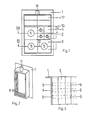
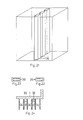
- Figure 1 depicts a frame 1 packed with blocks 2, 3, 4, of which blocks 2 and 3 contain bores 5 for cables to be passed through.
- the frame 1 of figure 2 is provided with blocks 2 or 3, depending on the diameter of the cables to be led through.
- a blind block 4 may be inserted.
- the blocks are positioned such that the grooves 7 of the blocks match up with the grooves 8 of the frame (figure 2), whereby closed ducts 9 are created between the blocks and the frame and between the blocks amongst themselves.
- the blocks can be compressed by a pressure plate 10 with the aid of a screw (not represented) enclosed within a bushing 11. After the desired compression has been attained, blocks of pressure-tight material 17 are introduced into the vacant space 12 between the pressure plate 10 and the frame 1, whereupon the pressure plate can be released.
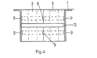
- Figure 3 schematically shows the course of the resultant air ducts 9 in a section of the frame with the blocks installed.
- Figure 4 is a cross-sectional view in which a rod-shaped element is represented as retaining means 13, supported with its ends in the grooves 8 of the frame.
- the retaining means 13 can be designed in various fashions.
- the simplest design is a flat rod with truncated ends 19, as represented in figures 9 and 10.
- the retaining means 13 may be provided with folded ends 20, as represented in figure 11.
- the retaining means is composed of two sections 21 with a C- or U-shaped cross-section and a thin plate 22 which is clamped in the grooves of the two sections 21.
- the sections 21 are individually supported in two parallel grooves 7 of the blocks 2 or 3 and grooves 8 of the frame.
- Figures 5 and 6 depict a block 2, consisting of two identical half blocks 14 and 15. This block may have one or more grooves 7 (three in this instance) round its circumference.
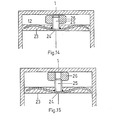
- the pressure plate consists of a corrugated metal plate 24 embedded in a block 23 made of an elastic material, on which plate a threaded end 25 has been welded. On top of the threaded end 25 a nut 26 is provided.
- the means of compression are introduced into the frame 1, the nut 26 on the threaded end 25 is in the position represented in figure 14.
- the threaded end 25 and hence the pressure plate 10 is forced down.
- a potential end position of nut 26 on the threaded end 25 is represented in figure 15.
- Figures 16 and 17 depict a first filler 27' with one curved end face 29 and a bore 30, composed of a part 30' whose diameter corresponds with the diameter of the threaded end 25 and a second part 30" having a larger diameter which corresponds with the dimensions of the nut 26. From the bcre 30 to the end face 31 runs a slit 32 which divides the block 27' virtually lengthwise into two.
- the block can flexibly enclose the threaded end 25 and the nut 26.
- FIGS 18, 19 and 20 depict a U-shaped second filler 27" corresponding with the first filler 27'.
- the outer surfaces of this block 27" are straight and the first filler 27' fits snugly into the U-shape.
- Metal plates 33 are embedded in the U-shaped block 27" near the ends of the legs of the U-shape so as to be perpendicular to the longitudinal direction of the legs. From each plate 33 a screw spindle 34 runs all the way through the legs to emerge from the opposite surface, with the centre line of each screw spindle 34 parallel to the long direction of the corresponding leg of the U-shape.
- a clamping plate 35 and nuts (not shown) fitting the screw spindles 34 are provided for tight joining together and compression of the fillers 27' and 27". By turning the nuts, the elastic material is squeezed together between the plates 33, and the fillers 27 hermetically seal the free space 12.
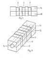
- adjoining frames 16, as represented in figures 7 and 8 it is furthermore possible with adjoining frames 16, as represented in figures 7 and 8, to attain an additional reduction of the heat transfer by the provision of an open slit 18 in the longitudinal partition.
- the amount of material to be used is thereby decreased as well.
- the partition may also consist of a number of oblong hollow sections 36 which have been placed vertically between the two subspaces at regular intervals, as represented diagrammatically in figure 21.
- the examples of figures 22 and 23 show that the sections 36 may have a rectangular or hexagonal cross-section.
- the spaces 37 between the sections 36 will contribute to a further lessening of the heat transfer across the filled frame 1. As the outermost sections are located at some distance from the outer edge of frame 1, the section 36 will be sealed off from the ambient medium by the elastic material of the surrounding blocks 2.
- Spacing blocks 38 may be fitted between the sections 36 to aid in correct positioning of the sections inside the frame 1, for instance as represented diagrammatically in figure 24.
Landscapes
- Engineering & Computer Science (AREA)
- Architecture (AREA)
- Civil Engineering (AREA)
- Structural Engineering (AREA)
- General Engineering & Computer Science (AREA)
- Mechanical Engineering (AREA)
- Installation Of Indoor Wiring (AREA)
- Glass Compositions (AREA)
- Sealing Battery Cases Or Jackets (AREA)
- Gasket Seals (AREA)
- Separation By Low-Temperature Treatments (AREA)
- Pharmaceuticals Containing Other Organic And Inorganic Compounds (AREA)
- Luminescent Compositions (AREA)
- Television Systems (AREA)
- Transition And Organic Metals Composition Catalysts For Addition Polymerization (AREA)
- Saccharide Compounds (AREA)
- Electrical Discharge Machining, Electrochemical Machining, And Combined Machining (AREA)
- Manufacturing Of Electric Cables (AREA)
Claims (10)
Priority Applications (1)
| Application Number | Priority Date | Filing Date | Title |
|---|---|---|---|
| AT85201806T ATE35448T1 (de) | 1984-11-30 | 1985-11-08 | Abdichtungssystem. |
Applications Claiming Priority (2)
| Application Number | Priority Date | Filing Date | Title |
|---|---|---|---|
| NL8403650A NL8403650A (nl) | 1984-11-30 | 1984-11-30 | Doorvoerinrichting. |
| NL8403650 | 1984-11-30 |
Publications (2)
| Publication Number | Publication Date |
|---|---|
| EP0183300A1 EP0183300A1 (de) | 1986-06-04 |
| EP0183300B1 true EP0183300B1 (de) | 1988-06-29 |
Family
ID=19844843
Family Applications (1)
| Application Number | Title | Priority Date | Filing Date |
|---|---|---|---|
| EP85201806A Expired EP0183300B1 (de) | 1984-11-30 | 1985-11-08 | Abdichtungssystem |
Country Status (10)
| Country | Link |
|---|---|
| US (1) | US4702444A (de) |
| EP (1) | EP0183300B1 (de) |
| JP (1) | JPS61135309A (de) |
| AT (1) | ATE35448T1 (de) |
| CA (1) | CA1253126A (de) |
| DE (1) | DE3563559D1 (de) |
| DK (1) | DK548585A (de) |
| FI (1) | FI854594L (de) |
| NL (1) | NL8403650A (de) |
| NO (1) | NO854763L (de) |
Cited By (1)
| Publication number | Priority date | Publication date | Assignee | Title |
|---|---|---|---|---|
| WO2004085899A1 (en) * | 2003-03-27 | 2004-10-07 | Galantai (Plastics) Group Limited | A mounting block |
Families Citing this family (49)
| Publication number | Priority date | Publication date | Assignee | Title |
|---|---|---|---|---|
| GB2186441B (en) * | 1986-02-11 | 1990-01-10 | Hawke Cable Glands Ltd | Improved transit for cables and pipes |
| GB2186440B (en) * | 1986-02-11 | 1990-03-14 | Hawke Cable Glands Ltd | Improved transit for cables and pipes |
| SE461887B (sv) * | 1986-04-28 | 1990-04-02 | Lycab Ab | Spaennanordning foer en kabelgenomfoering |
| DE3816870C2 (de) * | 1987-06-30 | 1993-09-30 | Heidelberger Druckmasch Ag | Einrichtung zum Durchführen von Kabeln |
| JPS6430415A (en) * | 1987-07-24 | 1989-02-01 | Takashi Mori | Cable inserting sash |
| DE3727160C1 (de) * | 1987-08-14 | 1988-09-08 | Plastoform Gmbh & Co Kg | Durchfuehrung fuer Leitungen durch eine Wandoeffnung |
| DE3736778C1 (de) * | 1987-10-30 | 1988-10-27 | Daimler Benz Ag | Abdichtende Durchfuehrung einer Rohrleitung |
| NL8901597A (nl) * | 1989-06-23 | 1991-01-16 | Pidou Bv | Doorvoerinrichting. |
| DE9000975U1 (de) * | 1990-01-29 | 1990-04-05 | Wolff, Anton, Dipl.-Ing., 3492 Brakel | Rahmen für Durchführung von Leitungen durch ein Bauteil |
| DE4040379A1 (de) * | 1990-12-17 | 1992-07-02 | Heidelberger Druckmasch Ag | Vorrichtung zur durchfuehrung von kabel |
| NL9101637A (nl) * | 1991-09-27 | 1993-04-16 | Csd Int Bv | Brandwerend systeem en werkwijze voor het vloeistof- en gasdicht doorvoeren van ten minste een kabel, buis of dergelijke, door een opening van een wand. |
| DE9211740U1 (de) * | 1992-09-01 | 1992-11-12 | Jürgen Albers GmbH, 6293 Löhnberg | Leitungseinführungsplatte |
| DE4305071A1 (de) * | 1992-09-29 | 1994-08-25 | Klein Guenther Industriebedarf | Packsystem für die Durchführung von Kabeln durch Schirmwände |
| GB2275577B (en) * | 1993-02-26 | 1996-05-29 | Hawke Cable Glands Ltd | Improvements in or relating to transits |
| NL9400745A (nl) * | 1994-05-04 | 1995-12-01 | Beele Eng Bv | Doorvoerinrichting. |
| USD439565S1 (en) | 1998-03-13 | 2001-03-27 | Lycab Ab | Holder for a packing piece for a cable lead through |
| DE69939203D1 (de) | 1998-10-16 | 2008-09-11 | Nilsen Dagfinn | Brandsichere Öffnung für Kabel oder Rohre |
| NL1010334C2 (nl) | 1998-10-16 | 2000-04-18 | Andre Van Dreumel | Brandwerende doorgang voor leidingen. |
| NL1016703C2 (nl) * | 2000-11-24 | 2002-05-27 | Beele Eng Bv | Doorvoerinrichting. |
| DE10150075A1 (de) * | 2001-10-10 | 2003-04-17 | Roxtec Ingenieur Gmbh | Modulare Schottung zur dichten Durchführung von Kabeln und Rohrleitungen durch Bauteile aller Art (mit nachweisbarer Dichte) |
| SE524043C2 (sv) * | 2002-06-05 | 2004-06-22 | Roxtec Int Ab | Kompressionsenhet |
| DE10313989B4 (de) * | 2003-03-27 | 2012-07-12 | Murrplastik Systemtechnik Gmbh | Kabeldurchführungsvorrichtung |
| DE102005056215B4 (de) * | 2005-11-25 | 2013-05-23 | Rittal Gmbh & Co. Kg | Vorrichtung zum Führen von Kabeln oder Leitungen |
| DE102005056214B3 (de) * | 2005-11-25 | 2007-06-21 | Rittal Gmbh & Co. Kg | Vorrichtung zum Führen von Kabeln oder Leitungen |
| US7427050B2 (en) * | 2006-01-10 | 2008-09-23 | Specified Technologies Inc. | Apparatus for adjustably retaining and sealing pathway conduits mounted extending through a wall panel |
| DE202006017659U1 (de) * | 2006-03-18 | 2007-08-02 | Weidmüller Interface GmbH & Co. KG | Dichtung für eine Gehäusedurchführung für ein Kabel |
| DE102008012460C5 (de) * | 2008-03-04 | 2013-04-25 | Berthold Sichert Gmbh | Bodenplatte oder Kabelverteilerschrank mit einer Bodenplatte und Montageverfahren |
| US20100123048A1 (en) * | 2008-11-18 | 2010-05-20 | Pollard Jr Michael E | Cable bus support block and system |
| US8294030B2 (en) * | 2008-11-18 | 2012-10-23 | MP Husky | Cable bus support block and system |
| GB0901678D0 (en) * | 2009-02-02 | 2009-03-11 | Beele Eng Bv | Assembly for sealing a round tubular opening through which a tube, duct or cable extends |
| US8664544B2 (en) * | 2010-07-29 | 2014-03-04 | Hydac Accessories Gmbh | Attachment system for cables, in particular for wind turbines |
| DE102010037463A1 (de) * | 2010-09-10 | 2012-03-15 | Phoenix Contact Gmbh & Co. Kg | Rahmen eines Kabeleinführungssystems und Kabeltülle hierfür |
| DE102011054294A1 (de) * | 2011-10-07 | 2013-04-11 | Phoenix Contact Gmbh & Co. Kg | Kabeldurchführung und Verfahren zur Montage einer Kabeldurchführung |
| NL1040892B1 (en) * | 2014-07-16 | 2016-08-16 | Beele Eng Bv | System for holding in a conduit cables or ducts with different diameters. |
| GB2537599A (en) * | 2015-04-13 | 2016-10-26 | E-Riser Ltd | Construction equipment and methods (locator) |
| SE538884C2 (en) * | 2015-05-04 | 2017-01-24 | Roxtec Ab | Compression wedge for a lead-through system |
| CN105033941B (zh) * | 2015-08-27 | 2017-03-22 | 上海怡博船务有限公司 | 一种门式安装夹具 |
| SE539322C2 (en) * | 2015-11-18 | 2017-07-04 | Roxtec Ab | Transition and module |
| DE202016103494U1 (de) * | 2016-06-30 | 2017-07-06 | Conta-Clip Verbindungstechnik Gmbh | Kabelwanddurchführung und Bausatz |
| CA3143151C (en) | 2017-05-02 | 2025-09-23 | Superior Tray Systems Inc. | ELECTRICAL SUPPLY STRUCTURES |
| WO2019077387A1 (en) * | 2017-10-17 | 2019-04-25 | Framatome | CABLE-CONDUCTIVE THROUGH ASSEMBLY, ELECTRICAL ASSEMBLY, ELECTRICAL CABINET AND METHOD THEREOF |
| IT201700119840A1 (it) * | 2017-10-23 | 2019-04-23 | Wallmax S R L | Elemento di riempimento per moduli passacavi. |
| DE102018218426A1 (de) * | 2018-10-29 | 2020-04-30 | Icotek Project Gmbh & Co. Kg | Kabeldurchführung |
| DE202019002833U1 (de) * | 2019-07-09 | 2020-07-16 | Kuka Deutschland Gmbh | Kabeldurchführung für einen Steuerungsschrank |
| SE543875C2 (en) * | 2020-02-04 | 2021-08-17 | Roxtec Ab | Transit for cables or pipes through a partition |
| US20220224097A1 (en) * | 2021-01-14 | 2022-07-14 | Quanta Computer Inc. | Cable-entry device for an electronic chassis |
| SE545999C2 (en) * | 2021-06-30 | 2024-04-09 | Roxtec Ab | A sealing module for cables or pipes, a transit system comprising such a sealing module, and a method of manufacturing a sealing module |
| US12322942B2 (en) | 2021-07-12 | 2025-06-03 | Martin Cox | Rigid bus ducts |
| US12117114B2 (en) * | 2021-09-09 | 2024-10-15 | Fast Valve Llc | Cleanroom wall passthrough |
Family Cites Families (9)
| Publication number | Priority date | Publication date | Assignee | Title |
|---|---|---|---|---|
| NL84538C (de) * | 1900-01-01 | |||
| US120884A (en) * | 1871-11-14 | Improvement in telegraph-insulators | ||
| US1022026A (en) * | 1911-07-24 | 1912-04-02 | Guthrie Mitchell Company | Insulator. |
| US3282544A (en) * | 1963-03-11 | 1966-11-01 | Lyckeaborgs Bruk Ab | Tight lead-through inlet frame device for electrical lines |
| US3489440A (en) * | 1966-04-18 | 1970-01-13 | Lyckeaborgs Bruk Ab | Tight lead-through inlet frame device |
| DE2524113C3 (de) * | 1975-05-30 | 1980-05-29 | Gerhard 6954 Hassmersheim Staudt | Verfahren zum Verschotten von elektrischen Leitungen oder Kabeln in Wand- oder Deckendurchführungen von Gebäuden |
| SE415619B (sv) * | 1979-01-18 | 1980-10-13 | Lyckeaborgs Bruk Ab | Genomforing for brandseker forleggning av elektriska kablar genom en oppning i en vegg eller liknande |
| DE2908163A1 (de) * | 1979-03-02 | 1980-09-11 | Klein Guenther Industriebedarf | Kabeldurchfuehrung, insbesondere bei schotten auf schiffen o.dgl. |
| DE8018534U1 (de) * | 1980-07-10 | 1981-01-15 | Licentia Patent-Verwaltungs-Gmbh, 6000 Frankfurt | Kabeldurchführung |
-
1984
- 1984-11-30 NL NL8403650A patent/NL8403650A/nl not_active Application Discontinuation
-
1985
- 1985-11-08 DE DE8585201806T patent/DE3563559D1/de not_active Expired
- 1985-11-08 EP EP85201806A patent/EP0183300B1/de not_active Expired
- 1985-11-08 AT AT85201806T patent/ATE35448T1/de not_active IP Right Cessation
- 1985-11-15 US US06/798,754 patent/US4702444A/en not_active Expired - Fee Related
- 1985-11-18 CA CA000495548A patent/CA1253126A/en not_active Expired
- 1985-11-21 FI FI854594A patent/FI854594L/fi not_active IP Right Cessation
- 1985-11-27 DK DK548585A patent/DK548585A/da not_active Application Discontinuation
- 1985-11-28 NO NO854763A patent/NO854763L/no unknown
- 1985-11-29 JP JP60270571A patent/JPS61135309A/ja active Pending
Cited By (1)
| Publication number | Priority date | Publication date | Assignee | Title |
|---|---|---|---|---|
| WO2004085899A1 (en) * | 2003-03-27 | 2004-10-07 | Galantai (Plastics) Group Limited | A mounting block |
Also Published As
| Publication number | Publication date |
|---|---|
| DK548585D0 (da) | 1985-11-27 |
| FI854594A7 (fi) | 1986-05-31 |
| US4702444A (en) | 1987-10-27 |
| ATE35448T1 (de) | 1988-07-15 |
| DK548585A (da) | 1986-05-31 |
| CA1253126A (en) | 1989-04-25 |
| DE3563559D1 (en) | 1988-08-04 |
| EP0183300A1 (de) | 1986-06-04 |
| JPS61135309A (ja) | 1986-06-23 |
| NL8403650A (nl) | 1986-06-16 |
| NO854763L (no) | 1986-06-02 |
| FI854594A0 (fi) | 1985-11-21 |
| FI854594L (fi) | 1986-05-31 |
Similar Documents
| Publication | Publication Date | Title |
|---|---|---|
| EP0183300B1 (de) | Abdichtungssystem | |
| US5687527A (en) | Suspended ceiling for cleanrooms | |
| US4249353A (en) | Fire barrier assembly for electrical cable | |
| US3282544A (en) | Tight lead-through inlet frame device for electrical lines | |
| US2732226A (en) | Brattberg | |
| DE69219352T2 (de) | Isolierprofil und verfahren für einfache und mehrfache atmosphärisch isolierende baueinheiten | |
| CA1280870C (en) | Modular frame arrangement for clean room ceilings suspendable from the ceiling of a room for receiving filters having a fluid seal | |
| JP4913870B2 (ja) | ケーブルトランジットのための加圧密閉手段 | |
| EP0232839A2 (de) | Durchgang für Kabel und Rohre | |
| US5124507A (en) | Cable splice assembly for connecting and branching cables particularly telecommunication cables | |
| US4901956A (en) | Method of manufacturing gas tight and water tight cable transits and method of making same | |
| US3779585A (en) | Sealing means for an aperture in a panel or the like | |
| GB1596375A (en) | Splice case with gasket and closure mechanism therefor | |
| US3198561A (en) | High pressure duct connection | |
| DE958671C (de) | Dichte Durchfuehrung fuer Leitungsbuendel durch eine Wand | |
| DE2654806A1 (de) | Dichtende wanddurchfuehrung fuer leitungen und rohre | |
| US2739001A (en) | Gaskets with stops therein | |
| DE3216057A1 (de) | Druckausgleichende dichtung, insbesondere fuer kabelgarnituren | |
| SG6988G (en) | Weldless joint | |
| CN111527659B (zh) | 插入块和包括所述插入块的密封系统 | |
| JPS62132170A (ja) | 液体クロマトグラフ用カラム装置 | |
| DE4318127A1 (de) | Solarzylinder für eine Solarenergieanlage | |
| DE7731063U1 (de) | Metallgekapselte, isoliergasgefüllte Schaltanlage | |
| EP1398553A1 (de) | Abdichtbares Durchführungssystem | |
| GB2072790A (en) | Pipe leak repair muff |
Legal Events
| Date | Code | Title | Description |
|---|---|---|---|
| PUAI | Public reference made under article 153(3) epc to a published international application that has entered the european phase |
Free format text: ORIGINAL CODE: 0009012 |
|
| AK | Designated contracting states |
Kind code of ref document: A1 Designated state(s): AT BE CH DE FR GB IT LI LU NL SE |
|
| 17P | Request for examination filed |
Effective date: 19861107 |
|
| 17Q | First examination report despatched |
Effective date: 19870907 |
|
| GRAA | (expected) grant |
Free format text: ORIGINAL CODE: 0009210 |
|
| AK | Designated contracting states |
Kind code of ref document: B1 Designated state(s): AT BE CH DE FR GB IT LI LU NL SE |
|
| PG25 | Lapsed in a contracting state [announced via postgrant information from national office to epo] |
Ref country code: LI Effective date: 19880629 Ref country code: IT Free format text: LAPSE BECAUSE OF FAILURE TO SUBMIT A TRANSLATION OF THE DESCRIPTION OR TO PAY THE FEE WITHIN THE PRESCRIBED TIME-LIMIT;WARNING: LAPSES OF ITALIAN PATENTS WITH EFFECTIVE DATE BEFORE 2007 MAY HAVE OCCURRED AT ANY TIME BEFORE 2007. THE CORRECT EFFECTIVE DATE MAY BE DIFFERENT FROM THE ONE RECORDED. Effective date: 19880629 Ref country code: FR Free format text: THE PATENT HAS BEEN ANNULLED BY A DECISION OF A NATIONAL AUTHORITY Effective date: 19880629 Ref country code: CH Effective date: 19880629 Ref country code: BE Effective date: 19880629 Ref country code: AT Effective date: 19880629 |
|
| REF | Corresponds to: |
Ref document number: 35448 Country of ref document: AT Date of ref document: 19880715 Kind code of ref document: T |
|
| PG25 | Lapsed in a contracting state [announced via postgrant information from national office to epo] |
Ref country code: SE Effective date: 19880630 |
|
| REF | Corresponds to: |
Ref document number: 3563559 Country of ref document: DE Date of ref document: 19880804 |
|
| REG | Reference to a national code |
Ref country code: CH Ref legal event code: PL |
|
| EN | Fr: translation not filed | ||
| PG25 | Lapsed in a contracting state [announced via postgrant information from national office to epo] |
Ref country code: LU Free format text: LAPSE BECAUSE OF NON-PAYMENT OF DUE FEES Effective date: 19881130 |
|
| PLBE | No opposition filed within time limit |
Free format text: ORIGINAL CODE: 0009261 |
|
| STAA | Information on the status of an ep patent application or granted ep patent |
Free format text: STATUS: NO OPPOSITION FILED WITHIN TIME LIMIT |
|
| 26N | No opposition filed | ||
| PG25 | Lapsed in a contracting state [announced via postgrant information from national office to epo] |
Ref country code: DE Effective date: 19890801 |
|
| PG25 | Lapsed in a contracting state [announced via postgrant information from national office to epo] |
Ref country code: GB Effective date: 19891108 |
|
| GBPC | Gb: european patent ceased through non-payment of renewal fee | ||
| PGFP | Annual fee paid to national office [announced via postgrant information from national office to epo] |
Ref country code: NL Payment date: 19941130 Year of fee payment: 10 |
|
| PG25 | Lapsed in a contracting state [announced via postgrant information from national office to epo] |
Ref country code: NL Effective date: 19960601 |
|
| NLV4 | Nl: lapsed or anulled due to non-payment of the annual fee |
Effective date: 19960601 |