EP0182290A2 - Tête de fraisage - Google Patents
Tête de fraisage Download PDFInfo
- Publication number
- EP0182290A2 EP0182290A2 EP85114479A EP85114479A EP0182290A2 EP 0182290 A2 EP0182290 A2 EP 0182290A2 EP 85114479 A EP85114479 A EP 85114479A EP 85114479 A EP85114479 A EP 85114479A EP 0182290 A2 EP0182290 A2 EP 0182290A2
- Authority
- EP
- European Patent Office
- Prior art keywords
- cutter head
- base body
- cutting
- head according
- radial
- Prior art date
- Legal status (The legal status is an assumption and is not a legal conclusion. Google has not performed a legal analysis and makes no representation as to the accuracy of the status listed.)
- Ceased
Links
Images


Classifications
-
- B—PERFORMING OPERATIONS; TRANSPORTING
- B23—MACHINE TOOLS; METAL-WORKING NOT OTHERWISE PROVIDED FOR
- B23C—MILLING
- B23C5/00—Milling-cutters
- B23C5/16—Milling-cutters characterised by physical features other than shape
- B23C5/20—Milling-cutters characterised by physical features other than shape with removable cutter bits or teeth or cutting inserts
- B23C5/22—Securing arrangements for bits or teeth or cutting inserts
- B23C5/24—Securing arrangements for bits or teeth or cutting inserts adjustable
- B23C5/2462—Securing arrangements for bits or teeth or cutting inserts adjustable the adjusting means being oblique surfaces
-
- B—PERFORMING OPERATIONS; TRANSPORTING
- B23—MACHINE TOOLS; METAL-WORKING NOT OTHERWISE PROVIDED FOR
- B23C—MILLING
- B23C5/00—Milling-cutters
- B23C5/16—Milling-cutters characterised by physical features other than shape
- B23C5/20—Milling-cutters characterised by physical features other than shape with removable cutter bits or teeth or cutting inserts
- B23C5/22—Securing arrangements for bits or teeth or cutting inserts
- B23C5/2204—Securing arrangements for bits or teeth or cutting inserts with cutting inserts clamped against the walls of the recess in the cutter body by a clamping member acting upon the wall of a hole in the insert
- B23C5/2226—Securing arrangements for bits or teeth or cutting inserts with cutting inserts clamped against the walls of the recess in the cutter body by a clamping member acting upon the wall of a hole in the insert for plate-like cutting inserts fitted on an intermediate carrier, e.g. shank fixed in the cutter body
-
- B—PERFORMING OPERATIONS; TRANSPORTING
- B23—MACHINE TOOLS; METAL-WORKING NOT OTHERWISE PROVIDED FOR
- B23C—MILLING
- B23C5/00—Milling-cutters
- B23C5/16—Milling-cutters characterised by physical features other than shape
- B23C5/20—Milling-cutters characterised by physical features other than shape with removable cutter bits or teeth or cutting inserts
- B23C5/22—Securing arrangements for bits or teeth or cutting inserts
- B23C5/24—Securing arrangements for bits or teeth or cutting inserts adjustable
- B23C5/2472—Securing arrangements for bits or teeth or cutting inserts adjustable the adjusting means being screws
-
- B—PERFORMING OPERATIONS; TRANSPORTING
- B23—MACHINE TOOLS; METAL-WORKING NOT OTHERWISE PROVIDED FOR
- B23C—MILLING
- B23C5/00—Milling-cutters
- B23C5/16—Milling-cutters characterised by physical features other than shape
- B23C5/20—Milling-cutters characterised by physical features other than shape with removable cutter bits or teeth or cutting inserts
- B23C5/22—Securing arrangements for bits or teeth or cutting inserts
- B23C5/24—Securing arrangements for bits or teeth or cutting inserts adjustable
- B23C5/2486—Securing arrangements for bits or teeth or cutting inserts adjustable where the adjustment is made by elastically deforming the toolholders
-
- B—PERFORMING OPERATIONS; TRANSPORTING
- B23—MACHINE TOOLS; METAL-WORKING NOT OTHERWISE PROVIDED FOR
- B23C—MILLING
- B23C5/00—Milling-cutters
- B23C5/16—Milling-cutters characterised by physical features other than shape
- B23C5/20—Milling-cutters characterised by physical features other than shape with removable cutter bits or teeth or cutting inserts
- B23C5/22—Securing arrangements for bits or teeth or cutting inserts
- B23C5/24—Securing arrangements for bits or teeth or cutting inserts adjustable
- B23C5/2489—Securing arrangements for bits or teeth or cutting inserts adjustable where the adjustment is made by changing the inclination of the inserts
-
- Y—GENERAL TAGGING OF NEW TECHNOLOGICAL DEVELOPMENTS; GENERAL TAGGING OF CROSS-SECTIONAL TECHNOLOGIES SPANNING OVER SEVERAL SECTIONS OF THE IPC; TECHNICAL SUBJECTS COVERED BY FORMER USPC CROSS-REFERENCE ART COLLECTIONS [XRACs] AND DIGESTS
- Y10—TECHNICAL SUBJECTS COVERED BY FORMER USPC
- Y10S—TECHNICAL SUBJECTS COVERED BY FORMER USPC CROSS-REFERENCE ART COLLECTIONS [XRACs] AND DIGESTS
- Y10S82/00—Turning
- Y10S82/902—Oil grooving device
-
- Y—GENERAL TAGGING OF NEW TECHNOLOGICAL DEVELOPMENTS; GENERAL TAGGING OF CROSS-SECTIONAL TECHNOLOGIES SPANNING OVER SEVERAL SECTIONS OF THE IPC; TECHNICAL SUBJECTS COVERED BY FORMER USPC CROSS-REFERENCE ART COLLECTIONS [XRACs] AND DIGESTS
- Y10—TECHNICAL SUBJECTS COVERED BY FORMER USPC
- Y10T—TECHNICAL SUBJECTS COVERED BY FORMER US CLASSIFICATION
- Y10T407/00—Cutters, for shaping
- Y10T407/19—Rotary cutting tool
- Y10T407/1906—Rotary cutting tool including holder [i.e., head] having seat for inserted tool
- Y10T407/1908—Face or end mill
- Y10T407/1912—Tool adjustable relative to holder
- Y10T407/1914—Radially
- Y10T407/1916—And axially
- Y10T407/1918—Selectively
-
- Y—GENERAL TAGGING OF NEW TECHNOLOGICAL DEVELOPMENTS; GENERAL TAGGING OF CROSS-SECTIONAL TECHNOLOGIES SPANNING OVER SEVERAL SECTIONS OF THE IPC; TECHNICAL SUBJECTS COVERED BY FORMER USPC CROSS-REFERENCE ART COLLECTIONS [XRACs] AND DIGESTS
- Y10—TECHNICAL SUBJECTS COVERED BY FORMER USPC
- Y10T—TECHNICAL SUBJECTS COVERED BY FORMER US CLASSIFICATION
- Y10T407/00—Cutters, for shaping
- Y10T407/19—Rotary cutting tool
- Y10T407/1906—Rotary cutting tool including holder [i.e., head] having seat for inserted tool
- Y10T407/1908—Face or end mill
- Y10T407/192—Face or end mill with separate means to fasten tool to holder
- Y10T407/1922—Wedge clamp element
-
- Y—GENERAL TAGGING OF NEW TECHNOLOGICAL DEVELOPMENTS; GENERAL TAGGING OF CROSS-SECTIONAL TECHNOLOGIES SPANNING OVER SEVERAL SECTIONS OF THE IPC; TECHNICAL SUBJECTS COVERED BY FORMER USPC CROSS-REFERENCE ART COLLECTIONS [XRACs] AND DIGESTS
- Y10—TECHNICAL SUBJECTS COVERED BY FORMER USPC
- Y10T—TECHNICAL SUBJECTS COVERED BY FORMER US CLASSIFICATION
- Y10T407/00—Cutters, for shaping
- Y10T407/19—Rotary cutting tool
- Y10T407/1906—Rotary cutting tool including holder [i.e., head] having seat for inserted tool
- Y10T407/1932—Rotary cutting tool including holder [i.e., head] having seat for inserted tool with means to fasten tool seat to holder
-
- Y—GENERAL TAGGING OF NEW TECHNOLOGICAL DEVELOPMENTS; GENERAL TAGGING OF CROSS-SECTIONAL TECHNOLOGIES SPANNING OVER SEVERAL SECTIONS OF THE IPC; TECHNICAL SUBJECTS COVERED BY FORMER USPC CROSS-REFERENCE ART COLLECTIONS [XRACs] AND DIGESTS
- Y10—TECHNICAL SUBJECTS COVERED BY FORMER USPC
- Y10T—TECHNICAL SUBJECTS COVERED BY FORMER US CLASSIFICATION
- Y10T407/00—Cutters, for shaping
- Y10T407/22—Cutters, for shaping including holder having seat for inserted tool
- Y10T407/2222—Tool adjustable relative to holder
- Y10T407/2244—Tool adjustable relative to holder by movement of seat relative to holder
- Y10T407/2246—Pivoted seat
-
- Y—GENERAL TAGGING OF NEW TECHNOLOGICAL DEVELOPMENTS; GENERAL TAGGING OF CROSS-SECTIONAL TECHNOLOGIES SPANNING OVER SEVERAL SECTIONS OF THE IPC; TECHNICAL SUBJECTS COVERED BY FORMER USPC CROSS-REFERENCE ART COLLECTIONS [XRACs] AND DIGESTS
- Y10—TECHNICAL SUBJECTS COVERED BY FORMER USPC
- Y10T—TECHNICAL SUBJECTS COVERED BY FORMER US CLASSIFICATION
- Y10T408/00—Cutting by use of rotating axially moving tool
- Y10T408/83—Tool-support with means to move Tool relative to tool-support
- Y10T408/85—Tool-support with means to move Tool relative to tool-support to move radially
- Y10T408/858—Moving means including wedge, screw or cam
- Y10T408/8588—Axially slidable moving-means
- Y10T408/85884—Tool pivotally mounted on support
-
- Y—GENERAL TAGGING OF NEW TECHNOLOGICAL DEVELOPMENTS; GENERAL TAGGING OF CROSS-SECTIONAL TECHNOLOGIES SPANNING OVER SEVERAL SECTIONS OF THE IPC; TECHNICAL SUBJECTS COVERED BY FORMER USPC CROSS-REFERENCE ART COLLECTIONS [XRACs] AND DIGESTS
- Y10—TECHNICAL SUBJECTS COVERED BY FORMER USPC
- Y10T—TECHNICAL SUBJECTS COVERED BY FORMER US CLASSIFICATION
- Y10T408/00—Cutting by use of rotating axially moving tool
- Y10T408/83—Tool-support with means to move Tool relative to tool-support
- Y10T408/85—Tool-support with means to move Tool relative to tool-support to move radially
- Y10T408/858—Moving means including wedge, screw or cam
- Y10T408/8588—Axially slidable moving-means
- Y10T408/85892—Screw driven wedge or cam
-
- Y—GENERAL TAGGING OF NEW TECHNOLOGICAL DEVELOPMENTS; GENERAL TAGGING OF CROSS-SECTIONAL TECHNOLOGIES SPANNING OVER SEVERAL SECTIONS OF THE IPC; TECHNICAL SUBJECTS COVERED BY FORMER USPC CROSS-REFERENCE ART COLLECTIONS [XRACs] AND DIGESTS
- Y10—TECHNICAL SUBJECTS COVERED BY FORMER USPC
- Y10T—TECHNICAL SUBJECTS COVERED BY FORMER US CLASSIFICATION
- Y10T408/00—Cutting by use of rotating axially moving tool
- Y10T408/83—Tool-support with means to move Tool relative to tool-support
- Y10T408/85—Tool-support with means to move Tool relative to tool-support to move radially
- Y10T408/858—Moving means including wedge, screw or cam
- Y10T408/8593—Wedge moving perpendicular to tool-axis
-
- Y—GENERAL TAGGING OF NEW TECHNOLOGICAL DEVELOPMENTS; GENERAL TAGGING OF CROSS-SECTIONAL TECHNOLOGIES SPANNING OVER SEVERAL SECTIONS OF THE IPC; TECHNICAL SUBJECTS COVERED BY FORMER USPC CROSS-REFERENCE ART COLLECTIONS [XRACs] AND DIGESTS
- Y10—TECHNICAL SUBJECTS COVERED BY FORMER USPC
- Y10T—TECHNICAL SUBJECTS COVERED BY FORMER US CLASSIFICATION
- Y10T408/00—Cutting by use of rotating axially moving tool
- Y10T408/83—Tool-support with means to move Tool relative to tool-support
- Y10T408/85—Tool-support with means to move Tool relative to tool-support to move radially
- Y10T408/858—Moving means including wedge, screw or cam
- Y10T408/8595—Pivotable tool-support
Definitions
- the invention relates to a cutter head with an essentially cylindrical base body and a plurality of interchangeable cutting bodies which are arranged on the circumferential region and have at least one cutting edge in the axial and or radial direction of the base body.
- the invention has for its object to provide a cutter head of the type described in the introduction which, with high operational reliability and simple operability, enables an exact three-dimensional adjustment of the cutting bodies relative to the base body.
- each of the cutting bodies is mounted on a support part mounted on the base body, which can be adjusted radially and axially to the base body by means of separate adjusting devices arranged between the base body and the support part and can be fixed on the base body by means of a clamping device.
- the cutter head according to the invention is characterized by a number of considerable advantages.
- a carrier part which in turn is mounted on the base body of the cutter head, it is possible to use a very small cutting body, since the functional parts required for adjustment are not formed on the cutting body, but on the carrier part.
- the size and volume of the cutting bodies play a decisive role with regard to the manufacturing and processing costs.
- the cutter head according to the invention it is therefore possible to use cutting bodies of very small dimensions.
- the carrier part can be adjusted radially and axially to the base body by means of separate adjusting devices, so that the position of the cutting edges can be changed three-dimensionally relative to the base body.
- the creation of separate adjustment devices ensures that the adjustment process can also be carried out safely by inexperienced operating personnel.
- the position of the cutting body After the position of the cutting body has been set, it can be fixed to the base body by means of a separate clamping device, in order to ensure that an adjustment of the position of the cutting body is prevented in a safe manner during use of the cutter head.
- the fixation of the cutting body by the separate clamping device takes place independently of the adjusting devices, so that these are not influenced by the clamping device.
- the cutter head according to the invention is advantageously designed such that the carrier part is held in a groove which is arranged essentially radially to the axis of rotation of the base body and has surfaces which are essentially parallel in the radial direction. In this way it is ensured, on the one hand, that the carrier part can be adjusted both axially and radially, while, on the other hand, the forces transmitted to the cutting body and thus to the carrier part during the cutting process can be transferred to the base body in a reliable manner.
- the cutter head according to the invention Due to this type of force transfer from the engaged cutting edge to the base body, it is possible with the cutter head according to the invention to vary the configuration of the cutting body in a wide range, in particular to provide different cutting or rake angles and the To give cutting a geometry adapted to the respective machining case, without having to use a differently designed base body of the cutter head.
- Another decisive advantage results from the fact that the cutting body can consist of a wide variety of cutting materials in such a cutter head, so that such a cutter head can also be used universally with regard to future material developments.
- each of the adjusting devices is essentially designed in the form of a wedge which can be brought into interaction with the carrier part in the region of the groove.
- Such wedge-shaped adjusting devices are extremely economical to manufacture, on the one hand, and they are characterized by a simple and reliable mode of operation, since the fineness of the adjustability can be changed practically as desired by the angle of the wedge.
- the arrangement of the adjustment devices in the area of the groove of the carrier part ensures a particularly space-saving design of the cutter head, so that the largest possible number of cutting bodies can be arranged on the base body.
- An advantageous embodiment of the cutter head according to the invention is further provided in that for the axial adjustment of the carrier part, the axial adjustment wedge is arranged on the side of the carrier part opposite the axial feed direction of the base body and one essentially Chen has a radial threaded bore that is aligned with a threaded bore in the base body and that a differential screw for moving the axial adjusting wedge can be engaged with the two threaded bores.
- a design of the axial adjustment device is characterized by a high degree of operational reliability and simplicity, since the forces applied to the carrier part by the axial adjustment wedge are transferred directly to the base body.
- the arrangement of a differential screw makes it possible to set the carrier part in the smallest tolerances, which are in the range of 1/1000 mm.
- the use of a differential screw with a differentially running thread has the advantage that the movability of the wedge relative to the base body can be adapted to the particular area of use of the cutter head by changing the thread formation. Furthermore, the aligned threaded bores for receiving the differential screw are distinguished by, in comparison to known adjustment systems, extremely low manufacturing costs and by a surprisingly high effectiveness.
- the cutter head according to the invention is also distinguished in that, for the radial adjustment of the carrier part, the radial adjustment wedge is arranged on the side of the carrier part facing away from the direction of rotation of the base body and can be brought into engagement with an essentially radial bearing surface of the carrier part, and in that Area of the radial adjustment wedge of the base body has an essentially axially extending threaded bore, with which a collar screw can be brought into engagement, the screw head side of which can be brought into contact with the radial adjustment wedge.
- Such an arrangement of the radial adjustment wedge ensures that the cutting forces acting on the carrier part or the cutting body cause a load on the carrier part in the direction of the radial adjustment wedge, whereby a secure interaction between the carrier part, the radial adjustment wedge and the base body is guaranteed under all operating conditions.
- the radial adjustment wedge it is also possible with the radial adjustment wedge to vary the fineness of the adjustability by changing the wedge angle and to adapt it to the particular conditions of use of the cutter head.
- the adjustment process is carried out by means of a collar screw which is received in a thread provided in the base body. This type of adjustability of the radial adjustment wedge can be achieved with very low production costs and ensures the highest level of operational reliability.
- the cutting forces are transmitted from the cutting body via the carrier part and the radial adjustment wedge directly to the base body, the level of the force to be absorbed by the collar screw is extremely low with such a design.
- the cutter head according to the invention is further designed such that a clamping wedge is arranged on the side of the carrier part opposite the axial adjustment wedge, which is penetrated by a threaded bore which is aligned with a threaded bore of the base body, a differential screw for moving the threaded bore in the threaded bores Clamping wedge is arranged and that the support member is further provided with a threaded recess, which extends essentially in a radial plane to the base body, in which a guide screw for the radial movement of the support member can be guided and brought into contact with the base body.
- the arrangement of an additional clamping wedge results in the advantage that the position of the carrier part provided by means of the axial adjusting wedge and the radial adjusting wedge can be fixed relative to the base body without the radial or axial adjusting devices having to be actuated for this purpose. In this way it is easily possible to cut the cutting body with accuracies in the range of 1/1000 mm adjust. Since the clamping wedge is arranged on the side of the carrier part opposite the radial adjustment wedge and the forces applied by it act essentially in the same direction as the circumferential forces caused by the cutting process, there is an addition of these forces to a total force which is the force caused by the radial wedge counteracts.
- the carrier part and the cutting body can be dimensioned much smaller, which on the one hand reduces the manufacturing costs, in particular for the cutting body, and on the other hand a larger number of cutting bodies can be arranged on the circumference of the base body.
- the use of the tracking screw ensures that a minimum force is always present between the carrier part and the adjusting wedges or the clamping wedge, so that the carrier part is securely fixed to the base body even when the cutter head is not in use.
- the cutter head according to the invention is designed in such a way that the cutting body can be fastened to the carrier part by means of a fastening screw and can be pivoted about the axis of the fastening screw at least in a certain region and that the pivoting movement can be limited by means of two adjusting screws mounted in the carrier part.
- a pivotability of the cutting body ensures that, in addition to the axial and radial adjustability, it can be pivoted about an axis which is essentially tangential to the circumference of the base body.
- Such a pivoting movement proves to be particularly advantageous when standardized cutting bodies are used which are to be adapted in their position to special geometric conditions.
- a particularly favorable design of the cutter head according to the invention is further provided in that the cutting body is designed in the form of a cutting plate carrier carrying a cutting plate.
- Such standard cutting inserts can be made from a wide variety of cutting materials with or without special equipment, such as polycrystalline diamond or polycrystalline boron nitride, and they can also have a wide variety of cutting edge geometries or shapes.
- To adapt the cutter head to the corresponding standard insert it is only necessary to use an appropriate insert holder. This has the further advantage that it is possible to carry out shape milling work with the most complicated geometry with the cutter head according to the invention.
- a particularly favorable embodiment of the cutter head according to the invention is also given in that the cutting body has a bead provided with a radially outwardly facing contact surface which can be brought into engagement with a groove of the carrier part having a radially inwardly facing contact surface.
- Such a configuration makes it possible in a particularly simple manner to use the cutter head according to the invention also for high-speed milling work, since the centrifugal forces which occur can be absorbed in a safe manner by the form-fitting engagement of the bead in the groove, without the position of the cutting body having been adjusted is changed.
- a favorable embodiment of the cutter head according to the invention is further achieved in that the base body has an annular groove in its peripheral region, in which at least one balancing body can be fastened. This allows the implementation of high in a particularly simple manner Speed milling work required balancing of the cutter head by simply moving the balancing body without additional parts influencing the milling process being necessary.
- the cutter head is advantageously designed such that the base body is designed in the form of a carrier carrying the cutting bodies and an annular ring fastened to the carrier and having the annular groove and control surfaces.
- a configuration allows the carrier itself to be produced particularly easily and at low cost, in particular making the grooves for receiving the carrier parts and the adjusting wedges particularly easy.
- the carrier can be connected to the ring either by a press fit or by additional screws.
- the control surfaces formed on the ring make it particularly easy to check the concentricity of a cutter head used in a machine tool.
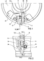
- a part of a first embodiment of the cutter head according to the invention is shown in a schematic representation in plan view.
- the cutter head has an essentially cylindrical base body 1, 2, which is provided on its outer circumference with a plurality of essentially radially arranged grooves 24, into each of which a carrier part 3, 4 can be inserted.
- a cutting plate carrier 5 is mounted on the carrier part, which in turn carries a cutting plate 9.
- the cutter head rotates counterclockwise during the cutting process.
- a radial adjustment wedge 13 is arranged, which acts between the base body 1, 2 and the carrier part 3, 4 for the radial adjustment of the carrier part 3, 4.
- the radial adjustment wedge is adjusted by means of a collar screw 14, which is shown schematically in a top view.
- a clamping wedge 15, which can be actuated by means of a differential screw 16, is arranged on the front side of the carrier part 3, 4 or the cutting plate carrier 5, as seen in the cutting direction.
- an adjusting screw 7 is also shown, which allows the adjustment of the insert holder 5 right relative to the carrier part 3, 4 is used.
- FIG. 2 shows a side view of the first exemplary embodiment of the cutter head from FIG. 1.
- the carrier part 3, 4 is arranged in the groove 24, which in turn carries the insert holder 5 with the insert 9.
- the insert 9 is fastened to the insert holder 5 by means of a fastening screw 10, the fastening screw 10 also serving to fasten the insert holder 5 to the carrier part 3, 4.
- the collar screw 14 is received in a bore lying parallel to the groove 24, its screw head is in contact with the radial adjustment wedge 13, which will be described in more detail later.
- the support part 3, 4 has a bore 8 'for receiving the in connection with FIG. 10 in more detail described adjustment screw 8. From the circumferential side of the cutter head, the differential screw 16 for actuating the clamping wedge 15 can also be adjusted using an appropriate tool.
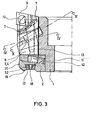
- the cutter head of Fig. 1 is shown in section along the line III-III of Fig. 2.
- the base body consists of a carrier 1 to which a ring 2 is fastened.
- the ring 2 can be attached by a shrink fit, but it is also possible to provide additional screws.
- the attachment of the ring 2 to the carrier 1 is not shown in FIG. 3.
- the ring 2 has an annular groove 32 which has a dovetail cross section.
- At least one balancing body 17 is inserted into the annular groove 32, which also has a corresponding dovetail cross section and can be fixed in a predeterminable position by means of a fastening screw 18.
- the ring 2 points furthermore a control surface 20 on its circumference and an annular control surface 19 on its side opposite the cutting body.
- the control surfaces 19 and 20 serve to control the concentricity of the cutter head used in a machine tool.
- an axial adjustment wedge 11 Arranged below the carrier part 3, 4 is an axial adjustment wedge 11, which comes into effect between the carrier part 3, 4 and the ring 2.
- the differential screw 12 is arranged in a bore which runs substantially parallel to the underlying support plane of the axial adjustment wedge 11 both in the axial adjustment wedge and in the ring 2.
- the bore is provided with a thread both in the ring 2 and in the axial adjustment wedge.
- the two threads can be designed with different pitches or with different directions of rotation, so that rotation of the differential screw 12 leads to the aforementioned displacement of the axial adjustment wedge 11.
- the tracking screw 8, the radial adjusting wedge 13 and the adjusting screws 7 are shown in broken lines in FIG. 3.
- the radial adjustment wedge 13 can be displaced in the axial direction by means of the collar screw 14 shown in FIG. 2, which causes the carrier part 3, 4 to be displaced in the radial direction.
- the exact position and arrangement of the adjusting screws 7 is explained in more detail in FIG. 6.
- the insert 9 is fastened to the carrier part 3, 4 or the insert holder 5 by means of the fastening screw 10.
- the tracking screw 8 is received in a threaded bore of the carrier part 3, 4, its axis is arranged essentially parallel to the groove 24 shown in FIG. 2 and inclined at a predetermined angle against the axis of rotation of the base body 1, 2.
- the guide screw 8 is explained in more detail in connection with FIG. 10.
- FIG. 4 shows a top view in schematic form of a section through the clamping wedge 15 and the radial adjustment wedge 13.
- the position of these two wedges has already been shown schematically in connection with FIG. 1.
- the radial adjustment wedge 13 can be displaced in the axial direction by means of the collar screw 14.
- the collar screw 14, which is not shown in FIG. 4 is screwed into a threaded bore 14 'of the base body 1, 2.
- the axis of the threaded bore 14 ′ runs, as can be seen in connection with FIG. 3, parallel to the edge of the radial adjustment wedge facing the outer circumference and inclined to the axis of rotation of the cutter head.
- the carrier part 3, 4 has a contact surface 27 which is in engagement with the radial adjustment wedge 13, which is otherwise arranged in a corresponding groove in the base body 1, 2 and is supported against the side walls of the groove.
- the clamping wedge 15 is arranged, analogously to the schematic illustration in FIG. 1.
- the clamping wedge 15 can be moved in a substantially radial direction relative to the base body 1, 2 by means of a differential screw 16.
- the clamping wedge 15 and the base body 1, 2 have a bore which is each provided with a thread with which the differential screw 16 is engaged. As described in connection with FIG. 3 and the differential screw 12 shown there, rotation of the differential screw 16 leads to a radial displacement of the clamping wedge 15.
- the thread 29 provided in the clamping wedge 15 can for this purpose differ from the thread 30 of the base body 1, 2 distinguish either by the slope or by the direction of rotation.
- Figure 5 shows, according to the section line VV of Fig. 2, a section through the ring 2 and the carrier 1, and through the Axialverstellkeil 11.
- Figure 5 shows again in detail the differential screw 12 and that through the axial wedge 11 and the ring 2 extending bore, which is provided with two different threads 25, 26. As already described, rotation of the differential screw 12 leads to a displacement of the axial wedge 11.
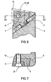
- Figure 6 shows a section along the line VI-VI of Fig. 1 through the carrier part 3 and the insert holder 5.
- the insert holder 5 is by means of the fastening screw 10 shown here only schematically, which in turn is arranged in a bore with the axis 21, with connected to the carrier part 3.
- a cutting plate 9, indicated only by dashed lines, is fastened to the cutting plate carrier 5 by means of the fastening screw 10.
- the insert holder 5 has on its side facing the carrier part 3 an essentially circular cylindrical shape, which has its center in the axis 21 of the fastening screw 10. The insert holder 5 can thus be pivoted about the axis 21 relative to the holder part 3.
- the carrier part 3 has two bores, essentially tangential to the cylindrical outer surface of the insert holder 5, in each of which an adjusting screw 7 is arranged, which in turn abuts the insert holder 5.
- the insert holder 5 can thus be pivoted about the axis 21 by screwing the respective adjusting screw 7.
- Figure 7 shows a section through the insert holder 5 and the carrier part 3 along the line VII-VII of Figure 6.
- the fastening screw 10, the insert 9 and the axis of rotation 21 can be seen.
- a corresponding design of the cross section of the insert holder 5 and the carrier part 3 realizes a positive connection, which prevents the insert holder 5 from moving in the direction of the axis of rotation 21.
- FIG. 8 shows a second exemplary embodiment of the cutter head according to the invention, which has a section shows which, analogous to FIG. 6, runs along the line VIII-VIII of FIG. 1.
- the carrier part 4 is constructed analogously to the carrier part 3 of FIG. 6, as is the mode of operation of the adjusting screws 7.
- the axes of rotation of the two adjusting screws 7 are inclined at an angle to one another, which results in even better adjustability.
- the cutting body 6 also has a cylindrical peripheral region and can be rotated about the axis 21 of the fastening screw 10.
- the exemplary embodiment shown in FIG. 8 shows a cutting body 6 which is used in high-speed milling.
- the use of a cutting plate 9 was dispensed with and the cutting body 6 itself was made from the appropriate material and provided with the desired cutting edges.
- FIG. 9 shows a section through the carrier part 4 and the cutting body 6 from FIG. 8.
- the cutting body 6 has a bead 23 which is designed to be rotationally symmetrical to the axis of rotation 21 of the fastening screw 10 and which engages with an essentially circular groove 22 in the carrier part 4 is feasible.
- the groove 22 and the bead 23 prevent, by means of a positive connection, that the cutting body 6 is thrown out of it by the influence of the centrifugal force during use of the cutter head.
- FIG. 10 In Fig. 10, according to the section line XX of Fig. 3, the tracking screw 8 and its arrangement in the carrier part 3, 4 is shown. Analogous to FIG. 4, the radial adjustment wedge 13 and the threaded bore 14 ′ for the collar screw 14 are also shown in FIG. 10.
- the tracking screw 8 is mounted in a threaded bore in the carrier part 3, 4 and causes a bias of the carrier part 3, 4 in the radial direction. The prestressing of the adjustment screw 8 ensures that the carrier part 3, 4 is constantly in contact located on the radial adjustment wedge 13.
- FIG. 11 shows a top view of the cutter head according to the invention similar to FIG. 1, whereby, analogously to FIG. 7, the interaction of insert holder 5, holder part 3, 4, insert 9 and fastening screw 10 is shown in connection with the radial adjustment wedge 13.
- FIG. 12 shows a section along the line XII-XII from FIG. 11, the position and configuration of the radial adjustment wedge 13 being shown in connection with the axis of rotation of the collar screw 14.
- the axis of rotation of the collar screw 14 or the threaded bore of the base body 1, 2 receiving it is parallel to the rear edge of the radial adjustment wedge 13.
- the runout of the individual cutting bodies relative to the base body 1, 2 is adjusted by adjusting the position of the respective carrier part 3, 4 relative to the Basic body 1.2.
- the longest cutting edge of all cutting bodies 5, 6, 9 provided on the cutter head is used as the starting point for this axial run-out, the other cutting edges are then set to the same dimension.
- the setting is made by loosening the adjustment screw 8 and then turning the differential screw 12, which results in a displacement of the axial adjustment wedge 11.
- the direction of rotation of the differential screw 12 depends on the type of thread realized with this screw.
- the guide screw 8 is then tightened and the cutting edge checked. This adjustment process can of course be repeated as often as soon as the position of the cutting edge relative to the cutter head has changed.
- the runout is adjusted analogously to the method of operation described above, so that the starting point is the cutting body 5, 9, 6, which has the largest radial dimensions.
- the remaining cutting elements are then adjusted to this dimension.
- the setting is also carried out by loosening the tracking screw 8 and turning the collar screw 14, which results in actuation of the radial adjustment wedge 13.
- the direction of rotation of the collar screw 14 also depends on the thread shape provided. Simultaneously with the rotation of the collar screw 14, the tracking screw 8 is actuated in a corresponding manner. Since a rotation of the adjustment screw 8 is necessary to adjust the axial and radial runout, it is particularly advantageous to carry out both adjustment processes practically simultaneously.
- the adjustment process described above can also be understood as a pre-adjustment phase, after which the same adjustment procedure is repeated again in a so-called final adjustment phase with the differential screw 16 slightly tightened.
- An actuation of the differential screw 16 leads to a displacement of the clamping wedge 15, by means of which the end position of the cutting body 5, 9, 6 reached relative to the base body 1,2 is fixed in the manner described above.
- the balancing body 17 is moved in the annular groove 32 and the finished knife head is balanced.
Applications Claiming Priority (2)
| Application Number | Priority Date | Filing Date | Title |
|---|---|---|---|
| DE19843441821 DE3441821A1 (de) | 1984-11-15 | 1984-11-15 | Messerkopf |
| DE3441821 | 1984-11-15 |
Publications (2)
| Publication Number | Publication Date |
|---|---|
| EP0182290A2 true EP0182290A2 (fr) | 1986-05-28 |
| EP0182290A3 EP0182290A3 (fr) | 1988-04-20 |
Family
ID=6250413
Family Applications (1)
| Application Number | Title | Priority Date | Filing Date |
|---|---|---|---|
| EP85114479A Ceased EP0182290A3 (fr) | 1984-11-15 | 1985-11-14 | Tête de fraisage |
Country Status (6)
| Country | Link |
|---|---|
| US (1) | US4692069A (fr) |
| EP (1) | EP0182290A3 (fr) |
| JP (1) | JPS61159303A (fr) |
| CA (1) | CA1255889A (fr) |
| DE (1) | DE3441821A1 (fr) |
| IL (1) | IL77042A0 (fr) |
Cited By (3)
| Publication number | Priority date | Publication date | Assignee | Title |
|---|---|---|---|---|
| EP0325212A2 (fr) * | 1988-01-19 | 1989-07-26 | ENTWICKLUNGSZENTRUM FÜR ZERSPANUNGSTECHNIK GMBH & CO. KG | Tête de fraisage |
| EP0835709A1 (fr) * | 1996-10-08 | 1998-04-15 | Kaiser Precision Tooling, Inc. | Dispositif d'ajustement pour outils de machine-outil |
| EP1827740A1 (fr) * | 2004-12-14 | 2007-09-05 | Seco Tools Ab | Perceuse pour usinage avec evacuation des copeaux comprenant une plaquette de coupe reglable |
Families Citing this family (27)
| Publication number | Priority date | Publication date | Assignee | Title |
|---|---|---|---|---|
| US4865336A (en) * | 1988-06-03 | 1989-09-12 | Carboloy Inc. | Apparatus for securing a cutting tool in a tool holder and machine tools employing the same |
| US5109425A (en) * | 1988-09-30 | 1992-04-28 | The United States Of America As Represented By The United States National Aeronautics And Space Administration | Method and apparatus for predicting the direction of movement in machine vision |
| US4927301A (en) * | 1988-12-27 | 1990-05-22 | Gte Valenite Corporation | Adjustable boring bar cartridge |
| DE3922963C2 (de) * | 1989-07-12 | 1994-06-01 | Widia Heinlein Gmbh | Drehräumwerkzeug |
| EP0556422A1 (fr) * | 1991-02-11 | 1993-08-25 | Valenite Inc. | Barre d'alésage ajustable améliorée |
| US5123787A (en) * | 1991-02-25 | 1992-06-23 | Gte Valenite Corporation | Machining tool |
| US5245896A (en) * | 1992-08-19 | 1993-09-21 | Kennametal Inc. | Quick-change tool holder with center height adjustment mechanism |
| US5261302A (en) * | 1992-10-07 | 1993-11-16 | Kennametal Inc. | Quick-change tool holder with adjustment mechanism for repeatable center-height adjustment |
| US5336026A (en) * | 1992-12-21 | 1994-08-09 | Valenite Inc. | Adjustable boring bar |
| DE4437426A1 (de) * | 1994-10-20 | 1996-04-25 | Widia Heinlein Gmbh | Fräser |
| DE19648039A1 (de) * | 1996-11-20 | 1998-02-26 | Bayerische Motoren Werke Ag | Messerkopf, insbesondere zum Planfräsen |
| US5913643A (en) * | 1997-04-22 | 1999-06-22 | Kennametal Inc. | Adjustable lead angle chamfering toolholder |
| DE19800440A1 (de) | 1998-01-08 | 1999-07-15 | Maier Kg Andreas | Messerkopf mit ein- bis dreidimensional verstellbarem Schneideinsatz und mit formschlüssig aufgenommenem Schneideinsatz |
| US6173637B1 (en) * | 1998-08-17 | 2001-01-16 | Lrh Enterprises, Inc. | Molding cutter head |
| IL127827A (en) * | 1998-12-29 | 2001-08-08 | Iscar Ltd | Milling a disc |
| DE10012818B4 (de) * | 2000-03-16 | 2006-04-06 | Wilhelm Fette Gmbh | Plan- oder Eckfräser |
| US7181993B2 (en) * | 2001-02-06 | 2007-02-27 | Good Earth Tool Company | Apparatus and process for cutting of extruded material |
| US7114890B2 (en) * | 2001-02-13 | 2006-10-03 | Valenite Inc. | Cutting tool adjustment device |
| EP1414606B1 (fr) * | 2001-08-08 | 2007-03-21 | Johne + Co. Präzisionswerkzeuge GmbH | Outil rotatif a plusieurs tranchants |
| US6702526B2 (en) | 2002-04-29 | 2004-03-09 | Kennametal Inc. | Cutting tool |
| EP1499479B1 (fr) | 2002-04-29 | 2011-11-09 | Kennametal Inc. | Outil de coupe |
| DE20303316U1 (de) * | 2003-02-28 | 2003-04-30 | Guehring Joerg | Drehangetriebenes Zerspanungswerkzeug |
| DE102005045751A1 (de) * | 2005-09-23 | 2007-03-29 | Sandvik Intellectual Property Ab | Einstellwinkelverstellung |
| KR100754056B1 (ko) * | 2005-11-21 | 2007-08-31 | 대구텍 주식회사 | 절삭공구 |
| DE202008006375U1 (de) * | 2008-05-08 | 2008-09-04 | Kennametal Inc. | Werkzeug zum Dreh-Dreh-Räumen oder Außenfräsen von Werkstücken |
| US8985916B2 (en) * | 2011-09-19 | 2015-03-24 | Sandvik Intellectual Property Ab | Flexible cartridge with precision adjustment |
| JP6512540B1 (ja) * | 2017-10-10 | 2019-05-15 | 株式会社タンガロイ | カートリッジ |
Citations (13)
| Publication number | Priority date | Publication date | Assignee | Title |
|---|---|---|---|---|
| US3121939A (en) * | 1957-01-18 | 1964-02-25 | O K Tool Co Inc | Cutting tool with indexable bit |
| DE1166591B (de) * | 1960-11-23 | 1964-03-26 | Rheinstahl Huettenwerke Ag | Messerkopf zum Schruppfraesen mit ausserhalb des Messerkopfes einstellbaren Auswechselmessern |
| DE2140004A1 (de) * | 1971-08-10 | 1973-02-22 | Walter Kieninger | Senk- und fraeswerkzeug |
| US3736811A (en) * | 1971-08-19 | 1973-06-05 | Gen Electric | Balance weight attachment for turbine wheels |
| US3755868A (en) * | 1971-07-23 | 1973-09-04 | Gen Electric | Adjustable cutting tool |
| DE2339873A1 (de) * | 1972-08-08 | 1974-02-28 | Mitsubishi Metal Mining Co Ltd | Einstellbares spanabhebendes werkzeug |
| GB1376510A (en) * | 1972-03-29 | 1974-12-04 | Bennett J T | Rotary tool holders and to cutting blades for insertion therein |
| EP0042667A2 (fr) * | 1980-06-24 | 1981-12-30 | General Electric Company | Ensemble de coins de positionnement réglable axialement et radialement pour une plaquette de coupe interchangeable d'un outil de coupe |
| EP0069316A1 (fr) * | 1981-07-08 | 1983-01-12 | Carboloy Inc. | Fraise à plaquette de finition réglable |
| DE3140905A1 (de) * | 1981-06-26 | 1983-05-05 | Sitzmann & Heinlein Gmbh, 8502 Zirndorf | "planmesserkopf, insbesondere schlichtkopf" |
| DE3236921C1 (de) * | 1982-10-06 | 1983-11-17 | Fried. Krupp Gmbh, 4300 Essen | Fräsmesserkopf |
| EP0126432A1 (fr) * | 1983-05-17 | 1984-11-28 | Walter Kieninger KG Hartmetallwerkzeugfabrik | Outil de fraisage |
| EP0167504A2 (fr) * | 1984-07-05 | 1986-01-08 | Seco Tools Ab | Fraise |
Family Cites Families (5)
| Publication number | Priority date | Publication date | Assignee | Title |
|---|---|---|---|---|
| US2430844A (en) * | 1944-06-12 | 1947-11-11 | Defiance Machine Works Inc | Rotary cutting tool |
| US2861471A (en) * | 1956-08-27 | 1958-11-25 | Leblond Mach Tool Co R K | Balancing device |
| GB1160425A (en) * | 1966-07-20 | 1969-08-06 | Marsh Brothers & Co Ltd | Improvements in or relating to Cutting Tools. |
| CH600977A5 (en) * | 1975-11-27 | 1978-06-30 | Stellram Sa | Angularly adjustable cutting tool for lathe |
| DE3036527A1 (de) * | 1980-09-27 | 1982-05-13 | Sandvik GmbH, 4000 Düsseldorf | Fraeswerkzeug |
-
1984
- 1984-11-15 DE DE19843441821 patent/DE3441821A1/de not_active Ceased
-
1985
- 1985-11-13 IL IL77042A patent/IL77042A0/xx not_active IP Right Cessation
- 1985-11-14 CA CA000495288A patent/CA1255889A/fr not_active Expired
- 1985-11-14 EP EP85114479A patent/EP0182290A3/fr not_active Ceased
- 1985-11-15 US US06/798,390 patent/US4692069A/en not_active Expired - Fee Related
- 1985-11-15 JP JP60256511A patent/JPS61159303A/ja active Pending
Patent Citations (13)
| Publication number | Priority date | Publication date | Assignee | Title |
|---|---|---|---|---|
| US3121939A (en) * | 1957-01-18 | 1964-02-25 | O K Tool Co Inc | Cutting tool with indexable bit |
| DE1166591B (de) * | 1960-11-23 | 1964-03-26 | Rheinstahl Huettenwerke Ag | Messerkopf zum Schruppfraesen mit ausserhalb des Messerkopfes einstellbaren Auswechselmessern |
| US3755868A (en) * | 1971-07-23 | 1973-09-04 | Gen Electric | Adjustable cutting tool |
| DE2140004A1 (de) * | 1971-08-10 | 1973-02-22 | Walter Kieninger | Senk- und fraeswerkzeug |
| US3736811A (en) * | 1971-08-19 | 1973-06-05 | Gen Electric | Balance weight attachment for turbine wheels |
| GB1376510A (en) * | 1972-03-29 | 1974-12-04 | Bennett J T | Rotary tool holders and to cutting blades for insertion therein |
| DE2339873A1 (de) * | 1972-08-08 | 1974-02-28 | Mitsubishi Metal Mining Co Ltd | Einstellbares spanabhebendes werkzeug |
| EP0042667A2 (fr) * | 1980-06-24 | 1981-12-30 | General Electric Company | Ensemble de coins de positionnement réglable axialement et radialement pour une plaquette de coupe interchangeable d'un outil de coupe |
| DE3140905A1 (de) * | 1981-06-26 | 1983-05-05 | Sitzmann & Heinlein Gmbh, 8502 Zirndorf | "planmesserkopf, insbesondere schlichtkopf" |
| EP0069316A1 (fr) * | 1981-07-08 | 1983-01-12 | Carboloy Inc. | Fraise à plaquette de finition réglable |
| DE3236921C1 (de) * | 1982-10-06 | 1983-11-17 | Fried. Krupp Gmbh, 4300 Essen | Fräsmesserkopf |
| EP0126432A1 (fr) * | 1983-05-17 | 1984-11-28 | Walter Kieninger KG Hartmetallwerkzeugfabrik | Outil de fraisage |
| EP0167504A2 (fr) * | 1984-07-05 | 1986-01-08 | Seco Tools Ab | Fraise |
Cited By (5)
| Publication number | Priority date | Publication date | Assignee | Title |
|---|---|---|---|---|
| EP0325212A2 (fr) * | 1988-01-19 | 1989-07-26 | ENTWICKLUNGSZENTRUM FÜR ZERSPANUNGSTECHNIK GMBH & CO. KG | Tête de fraisage |
| EP0325212A3 (fr) * | 1988-01-19 | 1991-01-09 | ENTWICKLUNGSZENTRUM FÜR ZERSPANUNGSTECHNIK GMBH & CO. KG | Tête de fraisage |
| EP0835709A1 (fr) * | 1996-10-08 | 1998-04-15 | Kaiser Precision Tooling, Inc. | Dispositif d'ajustement pour outils de machine-outil |
| EP1827740A1 (fr) * | 2004-12-14 | 2007-09-05 | Seco Tools Ab | Perceuse pour usinage avec evacuation des copeaux comprenant une plaquette de coupe reglable |
| EP1827740A4 (fr) * | 2004-12-14 | 2012-06-27 | Seco Tools Ab | Perceuse pour usinage avec evacuation des copeaux comprenant une plaquette de coupe reglable |
Also Published As
| Publication number | Publication date |
|---|---|
| JPS61159303A (ja) | 1986-07-19 |
| DE3441821A1 (de) | 1986-05-15 |
| IL77042A0 (en) | 1986-04-29 |
| US4692069A (en) | 1987-09-08 |
| CA1255889A (fr) | 1989-06-20 |
| EP0182290A3 (fr) | 1988-04-20 |
Similar Documents
| Publication | Publication Date | Title |
|---|---|---|
| EP0182290A2 (fr) | Tête de fraisage | |
| DE2339873C2 (de) | Anordnung zum Einstellen und Befestigen eines ein Schneidplättchen tragenden Blocks in einer nutförmigen Aufnahme im Werkzeugkörper eines spanabhebenden Werkzeugs | |
| EP0282090B1 (fr) | Fraise à plaquettes | |
| EP0404883B1 (fr) | Outil de percage/chanfreinage | |
| EP0472563B1 (fr) | Outil a magasin interchangeable deplacable | |
| DE3831535A1 (de) | Stirnfraeser | |
| DE2110078A1 (de) | Werkzeug zur spanabhebenden Bear bettung, insbesondere Frasmesserkopf | |
| EP0296460B1 (fr) | Outil pour l'usinage circonferentiel de pièces, en particulier pour le forage | |
| EP1718430A2 (fr) | Procede d'usinage par enlevement de copeaux de trous de precision | |
| EP0523404B1 (fr) | Outil à deux arêtes de coupe pour fraiser et alaiser | |
| EP0544658B1 (fr) | Outil de coupe servant a usiner les contours interieurs et exterieurs de pieces a usiner | |
| DE3530745A1 (de) | Messerkopf | |
| AT398049B (de) | Werkzeugträger zum wirbeln bzw. schälen von aussengewinden, schnecken und profilen | |
| EP0275923A2 (fr) | Dispositif de serrage de pièces | |
| CH657086A5 (de) | Messerkopfvorrichtung fuer eine maschine zum bearbeiten, wie fraesen oder hobeln, von werkstuecken aus holz oder kunststoff. | |
| DE2533495B2 (de) | Bohrstange | |
| DE3432936A1 (de) | Entgratwerkzeug | |
| DE3734734C2 (fr) | ||
| EP0841116B1 (fr) | Méthode de travail de surfaces de pièces symétriques en rotation et outil employé | |
| DE3909643C2 (de) | Mehrschneidenwerkzeugkopf zur spanabhebenden Vor- und Feinbearbeitung mit kreisförmiger Schnittbewegung | |
| DE3246994C2 (fr) | ||
| EP0429074B1 (fr) | Tête de fraisage à finir des pièces, specialement pour des cylindres à impression en creux | |
| DE3401200A1 (de) | Bohr- und ausdrehwerkzeug | |
| DE2808866C2 (de) | Bohrwerkzeug für Bohrungen in Metallvollmaterial | |
| DE3635228C2 (fr) |
Legal Events
| Date | Code | Title | Description |
|---|---|---|---|
| PUAI | Public reference made under article 153(3) epc to a published international application that has entered the european phase |
Free format text: ORIGINAL CODE: 0009012 |
|
| AK | Designated contracting states |
Kind code of ref document: A2 Designated state(s): AT BE CH DE FR GB LI LU NL SE |
|
| TCNL | Nl: translation of patent claims filed | ||
| EL | Fr: translation of claims filed | ||
| PUAL | Search report despatched |
Free format text: ORIGINAL CODE: 0009013 |
|
| AK | Designated contracting states |
Kind code of ref document: A3 Designated state(s): AT BE CH DE FR GB LI LU NL SE |
|
| 17P | Request for examination filed |
Effective date: 19881020 |
|
| 17Q | First examination report despatched |
Effective date: 19891204 |
|
| STAA | Information on the status of an ep patent application or granted ep patent |
Free format text: STATUS: THE APPLICATION HAS BEEN REFUSED |
|
| 18R | Application refused |
Effective date: 19900625 |
|
| RIN1 | Information on inventor provided before grant (corrected) |
Inventor name: KIENINGER, WALTER |