EP0275923A2 - Dispositif de serrage de pièces - Google Patents
Dispositif de serrage de pièces Download PDFInfo
- Publication number
- EP0275923A2 EP0275923A2 EP88100415A EP88100415A EP0275923A2 EP 0275923 A2 EP0275923 A2 EP 0275923A2 EP 88100415 A EP88100415 A EP 88100415A EP 88100415 A EP88100415 A EP 88100415A EP 0275923 A2 EP0275923 A2 EP 0275923A2
- Authority
- EP
- European Patent Office
- Prior art keywords
- pin
- fastening
- machine table
- adapter plate
- plate
- Prior art date
- Legal status (The legal status is an assumption and is not a legal conclusion. Google has not performed a legal analysis and makes no representation as to the accuracy of the status listed.)
- Withdrawn
Links
Images


Classifications
-
- B—PERFORMING OPERATIONS; TRANSPORTING
- B25—HAND TOOLS; PORTABLE POWER-DRIVEN TOOLS; MANIPULATORS
- B25B—TOOLS OR BENCH DEVICES NOT OTHERWISE PROVIDED FOR, FOR FASTENING, CONNECTING, DISENGAGING OR HOLDING
- B25B5/00—Clamps
- B25B5/14—Clamps for work of special profile
- B25B5/147—Clamps for work of special profile for pipes
-
- B—PERFORMING OPERATIONS; TRANSPORTING
- B23—MACHINE TOOLS; METAL-WORKING NOT OTHERWISE PROVIDED FOR
- B23Q—DETAILS, COMPONENTS, OR ACCESSORIES FOR MACHINE TOOLS, e.g. ARRANGEMENTS FOR COPYING OR CONTROLLING; MACHINE TOOLS IN GENERAL CHARACTERISED BY THE CONSTRUCTION OF PARTICULAR DETAILS OR COMPONENTS; COMBINATIONS OR ASSOCIATIONS OF METAL-WORKING MACHINES, NOT DIRECTED TO A PARTICULAR RESULT
- B23Q3/00—Devices holding, supporting, or positioning work or tools, of a kind normally removable from the machine
- B23Q3/02—Devices holding, supporting, or positioning work or tools, of a kind normally removable from the machine for mounting on a work-table, tool-slide, or analogous part
- B23Q3/06—Work-clamping means
-
- B—PERFORMING OPERATIONS; TRANSPORTING
- B23—MACHINE TOOLS; METAL-WORKING NOT OTHERWISE PROVIDED FOR
- B23Q—DETAILS, COMPONENTS, OR ACCESSORIES FOR MACHINE TOOLS, e.g. ARRANGEMENTS FOR COPYING OR CONTROLLING; MACHINE TOOLS IN GENERAL CHARACTERISED BY THE CONSTRUCTION OF PARTICULAR DETAILS OR COMPONENTS; COMBINATIONS OR ASSOCIATIONS OF METAL-WORKING MACHINES, NOT DIRECTED TO A PARTICULAR RESULT
- B23Q3/00—Devices holding, supporting, or positioning work or tools, of a kind normally removable from the machine
- B23Q3/02—Devices holding, supporting, or positioning work or tools, of a kind normally removable from the machine for mounting on a work-table, tool-slide, or analogous part
- B23Q3/10—Auxiliary devices, e.g. bolsters, extension members
- B23Q3/103—Constructional elements used for constructing work holders
-
- B—PERFORMING OPERATIONS; TRANSPORTING
- B25—HAND TOOLS; PORTABLE POWER-DRIVEN TOOLS; MANIPULATORS
- B25B—TOOLS OR BENCH DEVICES NOT OTHERWISE PROVIDED FOR, FOR FASTENING, CONNECTING, DISENGAGING OR HOLDING
- B25B5/00—Clamps
- B25B5/06—Arrangements for positively actuating jaws
- B25B5/08—Arrangements for positively actuating jaws using cams
-
- B—PERFORMING OPERATIONS; TRANSPORTING
- B25—HAND TOOLS; PORTABLE POWER-DRIVEN TOOLS; MANIPULATORS
- B25B—TOOLS OR BENCH DEVICES NOT OTHERWISE PROVIDED FOR, FOR FASTENING, CONNECTING, DISENGAGING OR HOLDING
- B25B5/00—Clamps
- B25B5/06—Arrangements for positively actuating jaws
- B25B5/10—Arrangements for positively actuating jaws using screws
- B25B5/104—Arrangements for positively actuating jaws using screws with one screw and one clamping lever and one fulcrum element
- B25B5/105—Arrangements for positively actuating jaws using screws with one screw and one clamping lever and one fulcrum element with one end of the lever resting on a table and the screw being positioned between the ends of the lever
-
- B—PERFORMING OPERATIONS; TRANSPORTING
- B25—HAND TOOLS; PORTABLE POWER-DRIVEN TOOLS; MANIPULATORS
- B25B—TOOLS OR BENCH DEVICES NOT OTHERWISE PROVIDED FOR, FOR FASTENING, CONNECTING, DISENGAGING OR HOLDING
- B25B5/00—Clamps
- B25B5/16—Details, e.g. jaws, jaw attachments
-
- B—PERFORMING OPERATIONS; TRANSPORTING
- B29—WORKING OF PLASTICS; WORKING OF SUBSTANCES IN A PLASTIC STATE IN GENERAL
- B29C—SHAPING OR JOINING OF PLASTICS; SHAPING OF MATERIAL IN A PLASTIC STATE, NOT OTHERWISE PROVIDED FOR; AFTER-TREATMENT OF THE SHAPED PRODUCTS, e.g. REPAIRING
- B29C45/00—Injection moulding, i.e. forcing the required volume of moulding material through a nozzle into a closed mould; Apparatus therefor
- B29C45/17—Component parts, details or accessories; Auxiliary operations
- B29C45/1742—Mounting of moulds; Mould supports
Definitions
- the invention relates to a clamping device for workpieces, in particular pre-drilled mold plates of injection molding tools, on grooved machine tables of processing machines, with an alignment element which has a pin which can be inserted into a pre-bore of the mold plate, a guide projection which can be inserted into a groove in the machine table, and a radial projection the shaped plate and the machine table projecting collar.
- Injection molding tools have mold plates into which the shapes of the parts to be produced by injection molding have to be incorporated, as well as all other recesses, for example bores and pockets for inserts and guides.
- the mold plates In order to incorporate such recesses, the mold plates must all be aligned exactly the same, so that congruent recesses are made in mold plates that lie one on top of the other can.
- the mold plates are usually standard parts and as such have standardized pilot holes on which the alignment must take place, since an alignment at the edges of the plates would not be precise enough because of the tolerance existing between a pilot hole and an edge.
- the alignment of a form plate has to be carried out anew each time, so that each time the processing machine has to be set again to a zero point formed by the pilot hole and the coordinates of at least two holes. This is cumbersome and time consuming.
- the proposed alignment elements each have a collar which projects between the mold plate and the machine table in order to keep both at a distance from one another. This distance is necessary, for example, in order to be able to drill a hole in the mold plate without drilling into the machine table.
- the collar is in one piece with the associated pin.
- the invention has for its object to improve a clamping device in terms of its alignment element so that it can be designed more universally and in particular as a standard part for aligning pre-drilled mold plates of injection molding tools. This object is achieved in that the radially projecting spacer collar of the alignment element is a separate part which can be plugged onto its pin.
- the pin and the spacer collar cooperating therewith are each formed as separate parts. This is a basic requirement for the production of standard parts. For example, pegs of different diameters can be assembled with spacer collars of the same height, or pegs of the same diameter with spacer collars of different heights can be used. In addition, the manufacture of the parts is simplified.
- the pins can be manufactured, for example, as automatic turned parts, which significantly reduces the production costs.
- the spacer collars can also be made very easily. If they are manufactured as ring washers, mass-produced goods can be used.
- the pin of the alignment element has a stepped pin end on the machine table, onto which the spacer collar designed as an annular disk is attached. The end of the pin thus determines the location of the arrangement of the loose spacer collar.
- the plugging in the sense of a conventional plug connection is a sufficient type of assembly in most cases.
- Push-on can also be understood here to mean any other form-fitting assembly, for example by screwing or bayonet-like.
- the stepped pin end is advantageously shorter than the spacer collar thick. Therefore, it is not possible for the offset end of the spigot on the machine sits on the table.
- the pin can be used for mounting, that is, either for mounting the spacer collar or for mounting radially expandable parts of the pin or the alignment element.
- the pin has a recess with an undercut for an extraction tool.
- the pin of the alignment element in the pilot hole of the molding plate has a spreading part which is used for fastening and / or radial alignment.
- the alignment element is therefore no longer only used to align the mold plate, but also to remove the influence of radial tolerances of the pin and the pre-drilling of the mold plate and also its fastening, which previously had to be carried out in the usual way, for example with clamping blocks that fit into the grooves of the Machine table were mounted and the mold plate clamped on it.
- the alignment element thus enables the saving of tensioning clamps or makes them unnecessary at all.
- the expansion part is a longitudinally slotted sleeve with an inner cone, which is expandable on an outer cone of the pin, or the expansion part is a package consisting of spring clamping rings surrounding the pins.
- the expansion part can be expanded directly by a fastening screw engaging in the guide projection or the pin or with a pressure piece or by a pressure piece to be adjusted on the pin. With the help of these expansion parts and the actuating elements acting on them, the respectively required fastening and alignment requirements can be met.
- the expansion part is at least one self-contained cone ring which can be expanded with a second cone ring arranged concentrically to the pin or on an outer cone of the pin.
- a conventional, commercially available conical ring can be used to fix the pin in a pilot hole of the mold plate and / or to compensate for tolerances which the pilot hole and the pin have.
- two pairs of cone rings are arranged one above the other in a ring-shaped recess of the pin with a rectangular cross section and can be spread with a pressure piece acting on at least one of the cone rings.
- the use of cone ring pairs avoids the complex production of an outer cone of the pin.
- the spread of the second cone ring can be increased by the axial displacement, as well as the spreadability of the second cone ring itself.
- Two pairs of cone rings also increase the axial length on which the expansion takes place, so that there is better guidance and retention of the pin in the pilot hole.
- a particularly advantageous embodiment for tensioning a cone ring or for tensioning cone ring pairs has the features that the guide projection is at least axially firmly connected to the pin, which can be tensioned by a fastening screw and a fastening nut cooperating therewith in a groove of the machine table, and / or that the pin, if necessary, has a axially movable pressure piece which can be supported on the spacer collar and a fixed pressure shoulder arranged opposite this, on the other side of the cone ring or of the cone ring pairs.
- the pin presses itself with its pressure shoulder on the cone ring or the cone ring pairs, so that a significant simplification of the Clamping device in this area results, wherein the axially movable pressure piece limited on the pin can be a conventional part without fine tolerances and consequently with low manufacturing costs.
- the limitation of the mobility of the pressure piece also makes it possible to use it as a component which maintains the cohesion of the cone ring or the cone ring pairs with the pin.
- the expansion parts can also be directly without a pressure piece, for. B. can be stretched against the spacer collar.
- the fastening nut is part of a threaded hole strip which has at least one further threaded hole located outside the axial projection area of the alignment element, into which a strip handle and / or a fastening screw is screwed.
- the further threaded hole is advantageously used to one Attach a strip handle with which the threaded strip can be moved near the alignment element from above the adapter plate or the machine table.
- the further threaded hole can be used to screw in a fastening screw with which, for example, the adapter plate can be secured against movements directed perpendicular to the machine table by means of a clamping block.
- the pin has a threaded hole located above a fastening screw with a screw-down wrench that can be inserted therein and has a central hole for an actuating tool of the fastening screw.
- a clamping device for workpieces in particular pre-drilled mold plates of injection molding tools, is formed on grooved machine tables of processing machines in such a way that an adapter plate which can be aligned on the machine table is provided with two mutually perpendicular fastening grooves.
- each mold plate can be fastened in the two mutually perpendicular grooves without further alignment in such a way that the desired alignment and at the same time the zero point is set. It is assumed here that the adapter plate with its one groove is aligned parallel to the workbench grooves and that the intersection of the two mutually perpendicular grooves of the adapter plate was used to determine the zero point of the processing machines. If one assumes that the form plate has two diagonally opposite pre-bores, which define two straight lines parallel to the edges, which enclose a right angle, an arrangement and fastening of the form plate with the aid of the two mutually perpendicular grooves of the adapter plate inevitably brings about the desired alignment and zero point position . This applies regardless of the size or format of the form plate, provided that it only has at least the two predrilled holes described above.
- the two fastening grooves are each arranged near the edge of the adapter plate, because the pilot holes of the mold plates are also in each case near the edge, so that as a result, all the mold plates can be machined up to approximately the format of the adapter plate.
- the adapter plate expediently has further grooves parallel to one of the fastening grooves and / or further clamping bores. With the help of these additional grooves, it is possible to assign an additional fastening point to each molding plate.
- the adapter plate has a hole in the intersection of the two mutually perpendicular fastening grooves into which an alignment element for pre-drilled shaped plates is inserted with a fastening projection and can be screwed to the adapter plate. This makes it possible to fix the mold plate to be machined even at the zero point, where it would otherwise not be practically possible to fix a conventional alignment element.
- the adapter plate On the machine table side, the adapter plate is provided with a groove dowel parallel to the table groove or with two centering pieces that fit in the machine table grooves, one of which has an adjustment eccentric. While usually the groove fitting bar should be sufficient to align the adapter plate, the actuation of the adjustment eccentric can be used for an adjustment in older machine tables.
- the adapter plate has in its two fastening grooves at least three alignment elements which act as edge stops of a pre-bore-free shaped plate to be machined, and the shaped plate is fastened to the adapter plate at a distance from it when it is machined.
- mold plates that are completely free of pre-drilling can be machined, for example mold plates for injection molding tools.
- the clamping device having an adapter plate is also suitable for machining pre-bore-free shaped plates in such a way that, after this machining, they can be processed by the processing machine, starting from the zero point predetermined by the clamping plate, if they are used with the pre-drilled holes then produced using two in each other vertical mounting grooves arranged alignment elements are aligned.
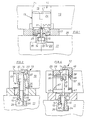
- the clamping device shown in FIG. 1 is arranged between a mold plate 10 and a machine table 11 and essentially consists of an alignment element 12.
- the alignment element 12 has a pin 13, a guide projection 15 fastened to it with a screw 14 and a pin 13 or the end collar 16 surrounding the end 16 thereof.
- the machine table 11 has a groove 20, which is T-shaped and receives the guide projection 15 with its groove section on the form plate side.
- the pin 13 has a recess 21 into which an extraction tool (not shown) can engage, for example a threaded rod, if the recess 21 has an internal thread.
- an internal thread is designated 22 in FIG. 2.
- the end 16 of the pin 13 is stepped, so it has a smaller outer diameter than the pin 13 in the area of its recess 21.
- In the transition area there is a groove 23 which has the circular-cylindrical fitting surface 24 which is seated in the correspondingly fitting hole surface 25 of the pilot hole 19 , from the likewise circular cylindrical outer peripheral surface of the pin end 16. Its outer circumference serves to support the spacer collar 17, the bore surface 26, cf. Fig.
- the pin end 16 can loosely surround, since it is not important here for a snug fit and only has to be ensured that the spacer collar assumes a sufficient position for supporting the mold plate 10 on the machine table 11. It is sufficient if the height of the spacer collar 17 is approximately exact, if the exact height between the mold plate 10 and the machine table 11 is not important. The prerequisite for this is that all spacer collars 17 have the same height.
- the pin end 16 is supported with its end face 27 on the surface 28 of the machine table 11. 2, a prismatic fitting recess 29 is machined into the end face 27, into which a fitting head 30 of the guide projection 15 engages.
- the fitting recess 29 has fitting surfaces 29 ⁇ which cooperate with the fitting surfaces 30 ⁇ of the fitting head 30 in the sense of a radial fit, so that the guide projection 15 and the pin 13 are to be assembled with a precise fit.
- the fit head 30 is as wide as the narrow area of the guide groove 20, cf. left guide projections 15 of FIG. 2, or it is narrower, cf. Fig. 1 and right guide projections 15 of Fig. 2.
- the guide projections 15 can be adapted to different groove widths without the need for different pins 13. Rather, the fit or the connection between the two parts 13, 15 is configured identically, so that standard series can be created from both components.
- Fig. 2 shows that the guide projection 15 is a prismatic body, the mating surfaces 30 ⁇ are correspondingly prismatic. It goes without saying, however, that the guide projection 15 and / or its guide head 30 can also be designed to be circular-cylindrical or otherwise suitable.
- the screw head 14 ' is arranged in a head recess 15' of the guide projection 15 and engages with its threaded shaft 14 'in a threaded bore 31 of the pin end 16.
- the pin 13 and the guide projection 15 are screwed together in such a way that the ring end face 32 of the Guide projection 15 is pulled against the end face 27 of the pin end 16.
- the fitting head 30 has a small axial distance from the pin 13 or from the pin end 16.
- Fig. 3 shows in its left half a fastening of the pin 13 and the guide projection 15, in which the fastening screw 14 is screwed through a through hole 33 with its threaded shaft 14 ⁇ into a threaded bore 32 of the guide projection 15.
- the guide projection 15 each has a radial projection 34, which is installed in the groove 20 of the machine table 11 and comes to rest against the undercuts 35, so that there is an axially positive connection, when the fastening screw 14 is screwed into the threaded bore 32 of the guide projection 15 in such a way that the end face 27 of the pin end 16 attaches to the surface 28 of the machine table 11.
- Such a fixing of the alignment elements 12 is particularly desirable when the alignment elements 12 also serve to transmit forces to the machine table 11 which arise during the processing of the molding plate 10 by the processing machines.
- left half the guide projection is formed according to FIG. 3, left half.
- the alignment element of FIG. 2, left half is then not used for the axial fastening, but primarily for minimizing radial tolerances, in particular in the area of the bore 19, and facilitates the handling of a large number of parts.
- the pin 13 has an expansion part 37 in the form of a slotted sleeve with a cylindrical outer circumference and a conical inner circumference, which is supported on the bore surface 25 of the pilot hole 19 or on the conical outer circumference of the pin 13, the largest outer circumference of which has some distance 36 from the bore surface 25 . If the fastening screw 14 is screwed into the guide projection 15 so that its radial projection 34 is supported on the undercut 35 of the groove 20, it presses with a bush 38 on the expansion part 37, which pushes onto the pin 13, in such a way that the latter remains centered and jammed.
- FIG. 4 shows two embodiments, which the use of spring tension rings 39 has in common. These spring tension rings 39 are shown in the right half of FIG. 4 in an untensioned position and in the left half of FIG. 4 in a tensioned position. Only the uppermost and lowest of the spring tension rings 39 are shown, but it is understood that a complete package of such spring tension rings 39 is present between a pressure piece 38 or 40 and a bearing collar 41 of the pin 13. This package is tensioned with the pressure pieces 38, 40. In doing so, their outer circumference increases in such a way that they become attached to the bore surface 25.
- the spring tension rings 39 are dimensioned such that they fix the alignment element 12 in the mold plate 10 when the package is compressed and thereby bridge radial tolerances to the bore 19 of the mold plate 10.
- FIG. 4 shows in the left half a pressure piece 38 which, similarly to the pressure piece 38 of FIG. 3, is adjusted axially toward the pin 13 with the fastening screw 14 becomes.
- the pressure piece 38 has an annular pressure projection 38 ⁇ , which flattens the spring washers 39. It is assumed that the pin 13 does not have to be axially attached to the machine table 11.
- the fastening of the pin 13 with a guide piece 15, already described with respect to FIG. 3, right half takes place in the threaded bore 32 of which the fastening screw 14 engages, whose head 14 ⁇ is located within the through bore 33 on a bore shoulder 41 supports.
- the pin 31 has an external thread 42, onto which a threaded ring is screwed as a pressure piece 40, which presses with an annular pressure projection 38 'onto the spring washers 39.
- the force is transmitted from the mold plate 10 via the spring clamping rings 39, the pin 13 and its pin end 16 and the fastening screw 14 and the guide projection 15 to the machine table 11.
- FIG. 5 shows an adapter plate 45 which, according to FIG. 6, has a bottom groove 44 into which a dowel bar engages and, with simultaneous engagement in a groove of the machine table 11, ensures a longitudinal alignment of the adapter plate 45.
- a groove system is worked into the clamping surface 46 of the adapter plate 45, which has at least two mutually perpendicular grooves 47, 48, which are profiled according to FIG. 1. They serve to accommodate alignment elements 12, which are installed in the above-described manner in pilot bores 19 of mold plates 10.
- a mold plate 10 is dash-dotted and shown with two pilot holes 19.
- the dash-dotted lines 49, 50 parallel to the grooves 47, 48 indicate approximately the maximum side lengths of mold plates which are on the adapter plate 45 can be processed.
- the mold plates 10 have to be clamped, for which purpose not only the alignment elements 12 described, for example, in FIGS. 3, 4 are used, which engage in the pilot bores 19 of the mold plates, but it is also possible to use conventional clamping blocks 51, which are also used in the Grooves 47, 48 of the adapter plate 45 can be anchored.
- Fig. 5 shows that the mutually perpendicular grooves 47, 48 of the adapter plate 45 are completely sufficient to set the zero point 52, which can be entered into the machine tool for all machining operations, in which form plates, with appropriate attachment of the adapter plate 45 on the machine table 11 10 can be aligned with alignment elements 12 in a simple manner with respect to this zero point 52.
- This alignment expediently takes place by engagement of these alignment elements 12 in the mutually diagonally opposite pilot bores 19 of the mold plate 10 or further mold plates.
- These pilot holes 19 are shown in dashed lines. It can be seen that, because of the defined position of these pilot bores 19 and the two grooves 47, 48, there is only one alignment position for a molding plate 10, which has that zero point 52. As a result, it is easily possible to process a large number of shaped plates, even in different formats, if they only have two predrilled holes per shaped plate.
- the adapter plate 45 is provided with a bore 56, to which a threaded bore 55 is arranged coaxially. 7, an alignment element 12 ⁇ is inserted, the pin 13 of which is provided with an integral guide projection 15a in the form of a round bolt, which is installed in the bore 56 with a fit. Installation or fastening is carried out using a fastening screw 14 which is screwed into the threaded bore 55.
- the adapter plate 45 has alignment holes 57. In contrast to the drawing, these are usually arranged in the center. With the help of these alignment holes 57, the adapter plate 45 can be aligned with respect to the machine table by using centering pieces 59 which engage on the one hand in the alignment holes 57 and on the other hand in the central groove of the machine table. 8, the upper centering piece 59 a one-piece pin, one end of which has flats 58 opposite one another, so that the centering piece 59 can thus be inserted into a groove in the machine table.
- the lower centering piece 59 in FIG. 8 also has such flats 58. However, these are located on a centering piece part 60 which is axially connected to a centering piece part 61 and is radially suitable.
- a special feature is that the axes 60 ⁇ , 61 ⁇ of the parts 60, 61 are not coaxial, but offset eccentrically.
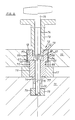
- the pin 13 is fastened to the machine table 11 with the fastening screw 14 and a nut 70 which is arranged in the groove section of the T-shaped groove 20 facing away from the molding plate.
- a support on the spacer collar 17 arranged between the machine table 11 and the molding plate 10 which in turn supports a pressure piece 69 which is axially displaceable to a limited extent on the pin end 16.
- This pressure piece 69 is fixed to the pin end 16 by means of the snap ring 76 so as to be movable to a limited extent.
- the guide piece 15 is attached in one piece and engages in the groove section of the T-shaped groove 20 on the form plate side.
- the pin end 16 is at a small distance 77 from the machine table 11 so that the pin 13 can be adjusted in the direction of the machine table 11 by the fastening screw 14 around the expansion part 37 to apply a pressure shoulder 71.
- the expansion part 37 consists of the two pairs of cone rings 66, 67.
- Each pair of cone rings 66, 67 has two cone rings 64, 65 which face each other and fit into the ring recess 68 between pin 13 and shaped plate 10 on the one hand and pressure piece 69 and pressure shoulder 71 on the other.
- the arrangement is such that the pressure shoulder 71 presses the outer cone ring in the upper cone ring pair 66, while in the lower cone ring pair 67 the pressure piece 69 presses the inner cone ring 65.
- the outer cone ring 64 of the lower cone ring pair 67 presses on the inner cone ring of the upper cone ring pair 66.
- a shortening of the distance between the pressure shoulder 71 and the pressure piece 69 causes the cone rings of the cone ring pairs 66, 67 to be pushed into one another and to expand within the scope of their extensibility. This results in the pin 13 jamming in the mold plate 10, combined with a pull-down effect of the pin 13, which consequently presses the pressure piece 69 against the spacer collar 17.
- the pull-down effect has the effect that vertical forces exerted on the mold plate 10 can be absorbed, which forces are transferred to the machine table 11 via the fastening screw 14 and the nut 70.
- the cone rings 64, 65 and the cone ring pairs 66, 67 also have the advantage that existing tolerances can be compensated for between the pin 13 and the pilot hole 19.
- the expansion part 37 can, as in the embodiments of FIGS. 3, 4, also be used for such a tolerance or clearance bridging, even if the pull-down or clamping effect of the molding plate 10 is not desired, or not sufficient in special cases is great.
- the fixing of the pin 13 with the aid of the fastening screw 14 via the fastening nut 70 has the advantage that the guide projection 15 can be formed in one piece with the pin 13 or its pin end 16.
- the pin 13 of the alignment element 12 is the only special part of the clamping device, the respective settlements of which in the area of the pin 13, the pin end 16 or the guide piece 15 can, however, be machined simply and reliably with sufficient accuracy.
- the accuracy, with a certain exception for the guide piece 15 has to be made only small requirements, so that the production costs are low.
- the further required parts of the alignment element 12, namely the cone rings 64, 65, the pressure piece 69, the spacer collar 17 and the fastening nut 70 are conventional parts which are mass-production-compatible and therefore inexpensive.
- Fig. 9 shows that the fastening screw 14 is inserted with its head 14 ⁇ in a stepped through hole 33, from which the fastening screw 14 can be easily unscrewed for loosening.
- An actuating tool 75 is used for this purpose, which engages in the polygonal inner recess of the head 14 'shown in the drawing. However, this does not remove the clamp fit of the pin 13 in the pilot hole 19. Rather, a hold-down wrench 73 is provided, which is screwed into a threaded bore 72 of the pin 13 located above the head 14 des or the fastening screw 14 and has a central bore 74 in order to be able to use the actuating tool 75.
- the alignment element 12 is axially penetrated by a through hole 33 through which a fastening screw 14 is inserted, so that its lower end, which is provided with a threaded shaft 14 ', projects beyond the guide projection 15 and engages in a threaded hole 79 of a fastening nut 70.
- the screw head 14 ⁇ of the fastening screw 14 is arranged in a head recess 33 ⁇ of the through hole 33 below an internal thread 22, which serves as an undercut for an extraction tool.
- the alignment element 12 or its pin 13 sits with a pressure shoulder 71 on a spacer collar 17 and presses this due to the screwing of the alignment element 12 to the machine table 11 against its surface 11rap.
- the pin 13 sits in a pilot hole 19 of a mold plate 10 and is chamfered at its upper and lower edge 13 ⁇ for easier separation from the mold plate 10.
- the fastening nut 70 is part of a threaded hole strip 80 which, in addition to the threaded hole 79, has a further threaded hole 81 in FIG. 10, which is arranged outside the projection area of the alignment element 12 or also outside the projection area of the molding plate 10.
- the fastening nut 70 can be arranged in the groove 20 of the table 11 by directing the end shown on the right in FIG. 10 in such a way that the fastening screw 14 can be screwed into the threaded hole 79 without great difficulty.
- the threaded perforated strip 80 is pulled upward due to its T-shaped cross section shown in FIG. 10a and against the undercuts 35 of the groove 20, so that the bracing takes place without the guide projection 15 being seated.
- a handle can be screwed to the further threaded hole 81, with which the threaded hole strip 80 can be directed from above the machine table 11.
- Fig. 10 shows a screwed into the further threaded hole 81 fastening screw 82 or a threaded bolt which has at its other, upper end 82 ⁇ a fastening nut 83 which presses via a washer 84 onto a clamping block 85 with which the mold plate 10 on the spacer collar 17 is clamped.
- the clamping takes place at the front end 85 ⁇ of the clamping block 85, in the rear end 85 ⁇ of which is screwed a threaded support 86 serving for height adjustment, which in turn is supported on the surface 11 ⁇ of the machine table 11.
- Such one Bracing of the mold plate 10 takes place when the alignment element 12 is not used for attachment, or when the attachment by the alignment element 12 z.
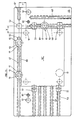
- FIG. 11 shows an adapter plate 45, which has two mutually perpendicular fastening grooves 47, 48. However, these do not extend to the zero point 52, like the grooves in FIG. 5, but end for manufacturing reasons with a certain distance therefrom in initial bores 55. Opposite the zero point 52 is an aligned fastening groove 47 ⁇ in which, for example, a clamping block 51 according to FIG. 5, top left, is attached. Another fastening groove 48 ⁇ runs parallel to the fastening groove 48 in order to have a further fastening possibility. Furthermore, there are alignment bores 57 and fastening bores 87 lying in alignment with them for aligning or fixing the adapter plate 45 on the machine table 11. This plate 45 also has, in accordance with the adapter plate 45 shown in FIG. 5, further parallel grooves 53.
- the fastening groove 47 there are two alignment elements 12 arranged at a distance from one another and the fastening groove 48 has an alignment element 12.
- the alignment is carried out by the pins 13 and the spacing of the plate 10 ⁇ from the adapter plate 45 through the spacer collar 17 of the alignment elements 12.
- To the same moderate support of the mold plate 10 ⁇ is also supported at its zero diagonally opposite corner 52 by a spacer collar 17.
- the mold plate 10 ⁇ is clamped with four clamping blocks 51.
- the shaped plate 10 ⁇ is free of pre-drilling and can be performed with the aid of the adapter plate 45 by a controlled drilling device in such a way that it can be further processed after the production of the pre-holes, which are indicated by dash-dotted lines in FIG. 11, for which purpose they have two of their pre-holes as described 5 is arranged or attached to the adapter plate 45.
- the pilot hole 19 ⁇ has center coordinates x, y, each of which corresponds to the radius of the dimensionally accurate pin 13, so that all pilot hole coordinates and coordinates of any further drilling or milling work in the clamping position shown in FIG.
- the plate 10 ⁇ are to take place in the machining program of the machine tool only have to be changed according to x, y. If the mold plate 10 ⁇ is loosened after such machining and clamped again according to FIG. 5, then all machining coordinates are in accordance with the program and further machining operations can be carried out using the program of the machine tool that is then not corrected by x, y.
Applications Claiming Priority (4)
| Application Number | Priority Date | Filing Date | Title |
|---|---|---|---|
| DE3701309 | 1987-01-17 | ||
| DE3701309 | 1987-01-17 | ||
| DE19873719010 DE3719010A1 (de) | 1987-01-17 | 1987-06-06 | Aufspannvorrichtung fuer werkstuecke |
| DE3719010 | 1987-06-06 |
Publications (2)
| Publication Number | Publication Date |
|---|---|
| EP0275923A2 true EP0275923A2 (fr) | 1988-07-27 |
| EP0275923A3 EP0275923A3 (fr) | 1990-04-25 |
Family
ID=25851649
Family Applications (1)
| Application Number | Title | Priority Date | Filing Date |
|---|---|---|---|
| EP88100415A Withdrawn EP0275923A3 (fr) | 1987-01-17 | 1988-01-14 | Dispositif de serrage de pièces |
Country Status (2)
| Country | Link |
|---|---|
| EP (1) | EP0275923A3 (fr) |
| DE (1) | DE3719010A1 (fr) |
Cited By (6)
| Publication number | Priority date | Publication date | Assignee | Title |
|---|---|---|---|---|
| EP0613757A1 (fr) * | 1993-02-20 | 1994-09-07 | Firma Gerhard Häberle | Dispositif de serrage pour pièces à travailler |
| DE4332751A1 (de) * | 1993-09-25 | 1995-03-30 | Hasco Normalien Hasenclever Co | Aufspannvorrichtung für Werkzeugmaschinen zur paßgenauen reproduzierbaren Anordnung eines Zentrierelementes in einer Zentrierbohrung |
| DE4341743A1 (de) * | 1993-12-08 | 1995-06-14 | Emil Stark | Aufspannplatte für eine Spannvorrichtung mit Einzugsnippel und Verfahren zur Herstellung der Aufspannplatte |
| DE29516236U1 (de) * | 1995-10-13 | 1995-11-30 | Gaertner Erwin | Spannplatte für eine Aufspannvorrichtung |
| CN102328215A (zh) * | 2011-07-14 | 2012-01-25 | 江苏汤臣汽车零部件有限公司 | 一种整体式减速器壳铣端盖连接法兰面工装 |
| CN102357816A (zh) * | 2011-09-16 | 2012-02-22 | 江苏华宇机械有限公司 | 用于固定系列零件的夹具 |
Families Citing this family (5)
| Publication number | Priority date | Publication date | Assignee | Title |
|---|---|---|---|---|
| DE3737672A1 (de) * | 1987-10-02 | 1989-04-13 | Manfred Schanz | Haltevorrichtung |
| DE8910764U1 (fr) * | 1989-09-09 | 1989-11-16 | Strack-Norma Gmbh, 5600 Wuppertal, De | |
| DE9001903U1 (fr) * | 1990-02-17 | 1990-08-23 | Meusburger Georg Ges.Mbh, Wolfurt, At | |
| DE29816822U1 (de) * | 1998-09-22 | 2000-02-03 | Meusburger Georg Gmbh | Spannvorrichtung zum Spannen von Formplatten für Spritzguß oder Druckgußmaschinen |
| DE202012013044U1 (de) * | 2012-02-28 | 2014-11-12 | Springer Gmbh | Antriebsvorrichtung zum Antreiben einer Vorrichtung zum Greifen und/oder Spannen eines Werkstückes, wie zum Beispiel eines Bleches oder dergleichen, und Vorrichtungen zum Greifen und/oder Spannen eines Werkstückes |
Citations (4)
| Publication number | Priority date | Publication date | Assignee | Title |
|---|---|---|---|---|
| GB744064A (en) * | 1953-03-31 | 1956-02-01 | Speed Tools Ltd | Improvements in or relating to screw and nut mechanisms |
| US3174746A (en) * | 1961-10-09 | 1965-03-23 | Baker Perkins Inc | Master fixture |
| DE7314053U (de) * | 1973-04-13 | 1973-08-09 | Halder E Maschinen Und Werkzeugfabrik | Richtanschlag |
| DE2309332A1 (de) * | 1972-02-24 | 1973-08-30 | Werkzeugmasch Okt Veb | Freitragende vorrichtung fuer werkzeugmaschinen zum selbsttaetigen spannen scheibenfoermiger werkstuecke |
-
1987
- 1987-06-06 DE DE19873719010 patent/DE3719010A1/de not_active Withdrawn
-
1988
- 1988-01-14 EP EP88100415A patent/EP0275923A3/fr not_active Withdrawn
Patent Citations (4)
| Publication number | Priority date | Publication date | Assignee | Title |
|---|---|---|---|---|
| GB744064A (en) * | 1953-03-31 | 1956-02-01 | Speed Tools Ltd | Improvements in or relating to screw and nut mechanisms |
| US3174746A (en) * | 1961-10-09 | 1965-03-23 | Baker Perkins Inc | Master fixture |
| DE2309332A1 (de) * | 1972-02-24 | 1973-08-30 | Werkzeugmasch Okt Veb | Freitragende vorrichtung fuer werkzeugmaschinen zum selbsttaetigen spannen scheibenfoermiger werkstuecke |
| DE7314053U (de) * | 1973-04-13 | 1973-08-09 | Halder E Maschinen Und Werkzeugfabrik | Richtanschlag |
Cited By (8)
| Publication number | Priority date | Publication date | Assignee | Title |
|---|---|---|---|---|
| EP0613757A1 (fr) * | 1993-02-20 | 1994-09-07 | Firma Gerhard Häberle | Dispositif de serrage pour pièces à travailler |
| US5499802A (en) * | 1993-02-20 | 1996-03-19 | Gerhard Haberle | Workpiece-holding system |
| DE4332751A1 (de) * | 1993-09-25 | 1995-03-30 | Hasco Normalien Hasenclever Co | Aufspannvorrichtung für Werkzeugmaschinen zur paßgenauen reproduzierbaren Anordnung eines Zentrierelementes in einer Zentrierbohrung |
| DE4341743A1 (de) * | 1993-12-08 | 1995-06-14 | Emil Stark | Aufspannplatte für eine Spannvorrichtung mit Einzugsnippel und Verfahren zur Herstellung der Aufspannplatte |
| DE4341743C2 (de) * | 1993-12-08 | 1998-01-29 | Emil Stark | Aufspannplatte für eine Spannvorrichtung mit Einzugsnippel und Verfahren zur Herstellung der Aufspannplatte |
| DE29516236U1 (de) * | 1995-10-13 | 1995-11-30 | Gaertner Erwin | Spannplatte für eine Aufspannvorrichtung |
| CN102328215A (zh) * | 2011-07-14 | 2012-01-25 | 江苏汤臣汽车零部件有限公司 | 一种整体式减速器壳铣端盖连接法兰面工装 |
| CN102357816A (zh) * | 2011-09-16 | 2012-02-22 | 江苏华宇机械有限公司 | 用于固定系列零件的夹具 |
Also Published As
| Publication number | Publication date |
|---|---|
| EP0275923A3 (fr) | 1990-04-25 |
| DE3719010A1 (de) | 1988-07-28 |
Similar Documents
| Publication | Publication Date | Title |
|---|---|---|
| DE2339873C2 (de) | Anordnung zum Einstellen und Befestigen eines ein Schneidplättchen tragenden Blocks in einer nutförmigen Aufnahme im Werkzeugkörper eines spanabhebenden Werkzeugs | |
| EP0312951B1 (fr) | Dispositif de serrage | |
| EP1813381B1 (fr) | Dispositif de serrage doté d'un mandrin pour le serrage fixe d'un élément de serrage | |
| EP0602204B1 (fr) | Element intermediaire pour dispositifs de serrage sur plaques a matrice de trous de machine-outil | |
| DE3733849C1 (de) | Maschinenschraubstock mit Kraftverstaerker | |
| EP0182290A2 (fr) | Tête de fraisage | |
| WO2011015259A1 (fr) | Support d'outil avec porte-outils interchangeables et porte-outil | |
| EP1757392B1 (fr) | Mandrin à diaphragme | |
| EP0275923A2 (fr) | Dispositif de serrage de pièces | |
| EP1468758B1 (fr) | Matrice pour jeu d'outils pour réaliser des joints mécaniques | |
| DE19917146A1 (de) | Nullpunktspannsystem | |
| EP0873816B1 (fr) | Cylindre pour positionnement et serrage rapide | |
| DE3634118C2 (fr) | ||
| EP2219811A2 (fr) | Dispositif pour serrer un porte-outil sur un mandrin de serrage pouvant être fixé sur une machine d'usinage | |
| EP0362753B1 (fr) | Dispositif de fixation | |
| DE2533495B2 (de) | Bohrstange | |
| DE3232496A1 (de) | Vorrichtung zur verschwenk- und feststellbaren lagerung eines maschinenschraubstockes auf einem maschinentisch | |
| EP1660262B1 (fr) | Point d'assemblage d'un outil | |
| EP0388783B1 (fr) | Outil de coupe pour l'usinage à enlèvement de copeaux | |
| EP1360024B1 (fr) | Tete de percage de precision a deplacement radial sans jeu | |
| EP2101944A1 (fr) | Outil d'usinage à enlèvement de copeaux | |
| EP0123918B1 (fr) | Mandrin de fraisage et de serrage | |
| DE2906840C3 (de) | Aufbohrwerkzeug | |
| CH664312A5 (de) | Bohr- und ausdrehwerkzeug. | |
| EP0178417A1 (fr) | Outil divisible pou l'usinage |
Legal Events
| Date | Code | Title | Description |
|---|---|---|---|
| PUAI | Public reference made under article 153(3) epc to a published international application that has entered the european phase |
Free format text: ORIGINAL CODE: 0009012 |
|
| AK | Designated contracting states |
Kind code of ref document: A2 Designated state(s): AT BE CH DE FR GB IT LI NL SE |
|
| PUAL | Search report despatched |
Free format text: ORIGINAL CODE: 0009013 |
|
| AK | Designated contracting states |
Kind code of ref document: A3 Designated state(s): AT BE CH DE FR GB IT LI NL SE |
|
| 17P | Request for examination filed |
Effective date: 19900323 |
|
| 17Q | First examination report despatched |
Effective date: 19910506 |
|
| STAA | Information on the status of an ep patent application or granted ep patent |
Free format text: STATUS: THE APPLICATION IS DEEMED TO BE WITHDRAWN |
|
| 18D | Application deemed to be withdrawn |
Effective date: 19910917 |