EP0182248A2 - Vorrichtung zum Absaugen von Sekretflüssigkeit aus einer Wunde - Google Patents
Vorrichtung zum Absaugen von Sekretflüssigkeit aus einer Wunde Download PDFInfo
- Publication number
- EP0182248A2 EP0182248A2 EP85114343A EP85114343A EP0182248A2 EP 0182248 A2 EP0182248 A2 EP 0182248A2 EP 85114343 A EP85114343 A EP 85114343A EP 85114343 A EP85114343 A EP 85114343A EP 0182248 A2 EP0182248 A2 EP 0182248A2
- Authority
- EP
- European Patent Office
- Prior art keywords
- hose
- vessel
- container
- negative pressure
- tube
- Prior art date
- Legal status (The legal status is an assumption and is not a legal conclusion. Google has not performed a legal analysis and makes no representation as to the accuracy of the status listed.)
- Granted
Links
Images
Classifications
-
- A—HUMAN NECESSITIES
- A61—MEDICAL OR VETERINARY SCIENCE; HYGIENE
- A61M—DEVICES FOR INTRODUCING MEDIA INTO, OR ONTO, THE BODY; DEVICES FOR TRANSDUCING BODY MEDIA OR FOR TAKING MEDIA FROM THE BODY; DEVICES FOR PRODUCING OR ENDING SLEEP OR STUPOR
- A61M1/00—Suction or pumping devices for medical purposes; Devices for carrying-off, for treatment of, or for carrying-over, body-liquids; Drainage systems
- A61M1/60—Containers for suction drainage, adapted to be used with an external suction source
- A61M1/63—Containers for suction drainage, adapted to be used with an external suction source with means for emptying the suction container, e.g. by interrupting suction
- A61M1/631—Emptying the suction container without interrupting suction
-
- A—HUMAN NECESSITIES
- A61—MEDICAL OR VETERINARY SCIENCE; HYGIENE
- A61M—DEVICES FOR INTRODUCING MEDIA INTO, OR ONTO, THE BODY; DEVICES FOR TRANSDUCING BODY MEDIA OR FOR TAKING MEDIA FROM THE BODY; DEVICES FOR PRODUCING OR ENDING SLEEP OR STUPOR
- A61M1/00—Suction or pumping devices for medical purposes; Devices for carrying-off, for treatment of, or for carrying-over, body-liquids; Drainage systems
- A61M1/71—Suction drainage systems
- A61M1/74—Suction control
-
- A—HUMAN NECESSITIES
- A61—MEDICAL OR VETERINARY SCIENCE; HYGIENE
- A61M—DEVICES FOR INTRODUCING MEDIA INTO, OR ONTO, THE BODY; DEVICES FOR TRANSDUCING BODY MEDIA OR FOR TAKING MEDIA FROM THE BODY; DEVICES FOR PRODUCING OR ENDING SLEEP OR STUPOR
- A61M1/00—Suction or pumping devices for medical purposes; Devices for carrying-off, for treatment of, or for carrying-over, body-liquids; Drainage systems
- A61M1/60—Containers for suction drainage, adapted to be used with an external suction source
- A61M1/63—Containers for suction drainage, adapted to be used with an external suction source with means for emptying the suction container, e.g. by interrupting suction
-
- A—HUMAN NECESSITIES
- A61—MEDICAL OR VETERINARY SCIENCE; HYGIENE
- A61M—DEVICES FOR INTRODUCING MEDIA INTO, OR ONTO, THE BODY; DEVICES FOR TRANSDUCING BODY MEDIA OR FOR TAKING MEDIA FROM THE BODY; DEVICES FOR PRODUCING OR ENDING SLEEP OR STUPOR
- A61M1/00—Suction or pumping devices for medical purposes; Devices for carrying-off, for treatment of, or for carrying-over, body-liquids; Drainage systems
- A61M1/71—Suction drainage systems
- A61M1/73—Suction drainage systems comprising sensors or indicators for physical values
- A61M1/732—Visual indicating means for vacuum pressure
Definitions
- the invention relates to a method for aspirating secretion fluid from a wound by means of a drain, which is connected via a hose to a vessel in which a negative pressure prevails, and a device for carrying out the method.
- the suction of the secretion fluid begins with maximum negative pressure, that is to say maximum suction.
- the vacuum and therefore the suction effect decrease in accordance with the amount of liquid sucked out. This is due to the fact that the negative pressure prevailing in the vessel is reduced more and more by the secretion fluid sucked into the vessel.
- What is annoying in this known method is not only the suction power, which may initially be too high, but above all the lack of possibility of adapting the suction power to the requirements and, for example, of being able to keep it approximately constant over a longer period.
- there is a risk of contamination at least then in the known method stands when it is necessary to replace the vessel, because the connection between the vessel and the hose to which the drain is connected must be opened.
- the invention has for its object to provide a method for aspirating secretion fluid from a wound that is both adaptable and eliminates the risk of contamination. This object is achieved by a method having the features of claim 1.
- the initially effective negative pressure need not be selected so that the suction effect is present for as long as possible. Rather, it can be chosen according to the initially optimal value.
- the vacuum which is also reduced in the method according to the invention by the secretion liquid entering the vessel, can be brought back to the desired value at any time, which can be the same as the initial value, but also lower or higher.
- the risk of contamination is excluded because the vessel can remain connected to the drain via the hose for the entire duration of the secretion fluid suction, since the secretion fluid that has accumulated in the vessel can be removed during the regeneration of the negative pressure.
- the contents thereof sucked out of the vessel are introduced through a hose into a collecting container by exposing the hose leading to the collecting container to the action of a hose pump.
- This also ensures that the system remains completely closed even during the regeneration phase. Since the suction of the contents of the vessel and the re-adjustment of the negative pressure in the vessel only need to be carried out from time to time, it is not necessary that the closed system is constantly connected to one Peristaltic pump is combined. Rather, it is sufficient to expose the hose leading from the vessel to the collecting container to the action of a hose pump only during each regeneration phase.
- Several secretion fluid suction systems can then be supplied with a single peristaltic pump, which considerably reduces the effort.
- the invention is also based on the object of providing a device for carrying out the method according to the invention which does not involve any application problems and is nevertheless so inexpensive that it can be used here as a one-way system. This object is achieved by a device having the features of claim 4.
- the solution according to the invention maintains the known vessel in which a negative pressure prevails, the use of the device according to the invention is familiar to the staff in hospitals and clinics. This already makes handling much easier.
- a hose pump needs to be attached to the hose leading from the vessel to the collecting container from time to time, or the hose pump attached has to be switched on, which likewise presents no difficulties.
- the handling compared to the known systems is even simplified because a vessel exchange is not necessary. If the hose pump is constantly combined with the second hose and has a design that ensures that the second hose is shut off, the hose pump itself can form the shut-off device. In the other cases, however, a shut-off device to be provided in addition to the hose pump is required in order to be able to shut off the second hose between the vessel and the hose container at the end of each regeneration process.
- a negative pressure display device is required.
- this display device is on the vessel provided that the device can be combined with it in a particularly simple manner.
- This vacuum indicator preferably consists of a bellows, the interior of which is connected to the interior of the vessel, a return spring acting on the bellows and a scale on which the prevailing vacuum can be read due to the position of the bellows or the length of the return spring.
- Such a vacuum display device is particularly advantageous in that it consists only of simple, inexpensive parts.
- the bellows can be made of rubber or plastic. The display device can therefore be thrown away together with the vessel after use. In the case of a very large display area, in order to avoid a relatively long bellows and a relatively long return spring, it can be more advantageous to provide at least two vacuum display devices of this type which have different measuring ranges.
- the container is preferably designed as a bottle and the collection container as a bag.
- a hose clamp can be provided as a shut-off device.
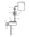
- a drain 1 designed in a known manner is connected via a first hose 2 to a dimensionally stable bottle 3 made of plastic.
- the neck, not shown, of the bottle for the drain 2 is located close to the lid which closes the bottle 3 at the top.
- this cover is provided with a single connecting piece, with which one end of a bellows 4 is tightly connected.
- the bellows 4 its interior with the interior the bottle 3 is connected via the connection piece, is connected at its end pointing away from the bottle 3 to one end of a helical tension spring 5, the other end of which is attached to a holder 6 firmly connected to the bottle 3.
- the spring 5 forms a return spring which tries to stretch the bellows 4 made of rubber or plastic.
- a negative pressure in the bottle 3 has the consequence that the bellows 4 is shortened and the spring 5 is lengthened accordingly.
- the bellows 4 and the spring 5 thus together form a sensor for the level of the negative pressure in the bottle.
- a scale 7 is arranged next to the bellows 4, on which the length of the bellows 4 and the associated height of the negative pressure in the bottle 3 can be read.
- the scale 7, the bellows 4 and the coil spring 5 with the holder 6 holding them therefore together form a vacuum indicator.
- this is provided with a nozzle, not shown, onto which one end of a second hose 8 is attached.
- This second hose leads to a collecting container 9, which in the exemplary embodiment is a bag and is expediently selected such that it can hold the entire amount of secretion liquid without having to be replaced. This allows the system to remain completely closed.
- the second hose 8 has a section 8 'made of silicone rubber, which is intended for interaction with a hose pump 11. Furthermore, the second hose 8 carries a manually operated hose clamp 12 in the area between the section 8 ′ and the collecting container 9.
- the bottle 3 is evacuated by means of the peristaltic pump 11 until the vacuum in the bottle 3 which is optimal for the suction of the wound secretion fluid is reached. Then the hose clamp 12 is closed and the Hose pump 11 switched off or completely removed so that it can be used for other purposes. Due to the increasing amount of secretion fluid that accumulates in the bottle 3, the negative pressure inside the bottle 3 decreases. This decrease can be read on the scale 7 because the spring 5 extends the bellows 4 accordingly.
- the peristaltic pump 11 is activated again by switching it on or by attaching it to the section 8 'of the hose 8 and then switching it on. While the hose pump 11 is operating, the hose clamp 12 must be open so that the secretion fluid pumped out of the bottle 3 can flow into the collecting container 9. The suction of the secretion liquid from the bottle 3 has the result that the negative pressure in the bottle 3 rises again. As soon as the desired value is reached, which can be seen on the scale 7, the hose clamp 12 is closed again and the hose pump 11 is switched off, possibly also separated from the section 8 '. After the suction of the secretion fluid has ended, all parts with the exception of the peristaltic pump 11 are thrown away.
- the negative pressure in the bottle 3 and thus the suction effect can be kept within any range during the suction of the secretion liquid.
- the closed microbiological system consisting of drain 1
- Hose 2 the bottle 3, the second hose 8 and the collecting container 9 not to be opened, so that there is no risk of contamination.
Landscapes
- Health & Medical Sciences (AREA)
- Heart & Thoracic Surgery (AREA)
- Vascular Medicine (AREA)
- Engineering & Computer Science (AREA)
- Anesthesiology (AREA)
- Biomedical Technology (AREA)
- Hematology (AREA)
- Life Sciences & Earth Sciences (AREA)
- Animal Behavior & Ethology (AREA)
- General Health & Medical Sciences (AREA)
- Public Health (AREA)
- Veterinary Medicine (AREA)
- External Artificial Organs (AREA)
- Media Introduction/Drainage Providing Device (AREA)
- Golf Clubs (AREA)
- Drying Of Solid Materials (AREA)
- Tyre Moulding (AREA)
- Massaging Devices (AREA)
Abstract
Description
- Die Erfindung betrifft ein Verfahren zum Absaugen von Sekretflüssigkeit aus einer Wunde mittels eines Drains, der über einen Schlauch mit einem Gefäß verbunden ist, in dem ein Unterdruck herrscht, sowie eine Vorrichtung zur Durchführung des Verfahrens.
- Bei den bekannten Verfahren dieser Art beginnt das Absaugen der Sekretflüssigkeit mit maximalem Unterdruck, also maximaler Saugwirkung. Entsprechend der abgesaugten Flüssigkeitsmenge nehmen der Unterdruck und damit auch die Saugwirkung ab. Bedingt ist dies dadurch, daß sich der im Gefäß herrschende Unterdruck durch die in das Gefäß gesaugte Sekretflüssigkeit mehr und mehr abbaut. Störend ist bei diesem bekannten Verfahren nicht nur die unter Umständen anfänglich zu hohe Saugleistung, sondern vor allem auch die fehlende Möglichkeit, die Saugleistung an die Erfordernisse anpassen und beispielsweise über einen längeren Zeitraum auch annähernd konstant halten zu können. Hinzu kommt noch, daß bei dem bekannten Verfahren zumindest dann eine Kontaminationsgefahr besteht, wenn ein Auswechseln des Gefäßes erforderlich ist, weil hierzu die Verbindung zwischen dem Gefäß und dem Schlauch, an den der Drain angeschlossen ist, geöffnet werden muß.
- Der Erfindung liegt die Aufgabe zugrunde, ein Verfahren zum Absaugen von Sekretflüssigkeit aus einer Wunde zu schaffen, das sowohl anpassungsfähig ist als auch eine Kontaminationsgefahr ausschließt. Diese Aufgabe löst ein Verfahren mit den Merkmalen des Anspruches 1.
- Dadurch, daß der Unterdruck in dem die abgesaugte Sekretflüssigkeit aufnehmenden Gefäß von Zeit zu Zeit auf einen wählbaren Wert regeneriert werden kann, braucht der anfänglich wirksame Unterdruck nicht so gewählt zu werden, daß die Saugwirkung möglichst lange vorhanden ist. Vielmehr kann er entsprechend dem anfänglich optimalen Wert gewählt werden. Ebenso kann anschließend der Unterdruck, welcher auch bei dem erfindungsgemäßen Verfahren durch die in das Gefäß gelangende Sekretflüssigkeit vermindert wird, zu jedem beliebigen Zeitpunkt wieder auf den gewünschten Wert gebracht werden, der gleich hoch wie der Ausgangswert, aber auch niedriger oder höher liegen kann. Ferner ist die Kontaminationsgefahr ausgeschlossen, weil das Gefäß während der gesamten Dauer der Sekretflüssigkeitsabsaugung über den Schlauch mit dem Drain verbunden bleiben kann, da bei der Regeneration des Unterdruckes die Sekretflüssigkeit, die sich im Gefäß angesammelt hat, abgeführt werden kann.
- Bei der bevorzugten Ausführungsform wird der aus dem Gefäß abgesaugte Inhalt desselben durch einen Schlauch hindurch in einen Sammelbehälter eingeleitet, indem der zum Sammelbehälter führende Schlauch der Einwirkung einer Schlauchpumpe ausgesetzt wird. Hierdurch ist ebenfalls sichergestellt, daß das System auch während der Regenerationsphase vollständig geschlossen bleibt. Da das Absaugen des Inhaltes des Gefäßes und die erneute Einstellung des Unterdrucks im Gefäß nur von Zeit zu Zeit zu erfolgen braucht, ist es nicht notwendig, das das geschlossene System ständig mit einer Schlauchpumpe kombiniert ist. Vielmehr genügt es, den vom Gefäß zum Sammelbehälter führenden Schlauch nur während jeder Regenerationsphase der Wirkung einer Schlauchpumpe auszusetzen. Es können dann mit einer einzigen Schlauchpumpe mehrere Sekretflüssigkeitsabsaugsysteme versorgt werden, was den Aufwand erheblich vermindert.
- Der Erfindung liegt auch die Aufgabe zugrunde, eine Vorrichtung zur Durchführung des erfindungsgemäßen Verfahrens zu schaffen, welche keine Anwendungsprobleme mit sich bringt und dennoch so kostengünstig ist, daß es hier als Einweg-System verwendet werden kann. Diese Aufgabe löst eine Vorrichtung mit den Merkmalen des Anspruches 4.
- Da die erfindungsgemäße Lösung das bekannte Gefäß, in dem ein Unterdruck herrscht, beibehält, ist insoweit der Gebrauch der erfindungsgemäßen Vorrichtung dem Personal in Krankenhäusern und Kliniken vertraut. Dies erleichtert bereits wesentlich die Handhabung. Hinzu kommt lediglich, daß von Zeit zu Zeit an den vom Gefäß zum Sammelbehälter führenden Schlauch eine Schlauchpumpe angesetzt oder die angesetzte Schlauchpumpe eingeschaltet zu werden braucht, was ebenfalls keine Schwierigkeiten bereitet. Die Handhbung gegenüber den bekannten Systemen wird sogar noch vereinfacht, weil ein Gefäßaustausch nicht erforderlich ist. Sofern die Schlauchpumpe ständig mit dem zweiten Schlauch kombiniert ist und eine Ausbildung hat, die sicherstellt, daß der zweite Schlauch abgesperrt wird, kann die Schlauchpumpe selbst die Absperrvorrichtung bilden. In den übrigen Fällen ist hingegen eine zusätzlich zur Schlauchpumpe vorzusehende Absperrvorrichtung erforderlich, um am Ende jedes Regenerationsvorganges den zweiten Schlauch zwischen dem Gefäß und dem Schlauchbehälter absperren zu können.
- Um den im System herrschenden Unterdruck ermitteln zu können, ist eine Unterdruck-Anzeigevorrichtung erforderlich. Bei einer bevorzugten Ausführungsform ist diese Anzeigevorrichtung an dem Gefäß vorgesehen, da sich mit ihm die Vorrichtung in besonders einfacher Weise kombinieren läßt. Vorzugsweise besteht diese Unterdruck-Anzeigevorrichtung aus einem Faltenbalg, dessen Innenraum mit dem Innenraum des Gefäßes in Verbindung steht, einer am Faltenbalg angreifenden Rückstellfeder und einer Skala, an welcher aufgrund der Stellung des Faltenbalges oder auch der Länge der Rückstellfeder der herrschende Unterdruck abgelesen werden kann. Besonders vorteilhaft ist eine derartige Unterdruck-Anzeigevorrichtung insofern, als sie nur aus einfachen, kostengünstigen Teilen besteht. Der Faltenbalg kann dabei aus Gummi oder Kunststoff bestehen. Die Anzeigeeinrichtung kann deshalb zusammen mit dem Gefäß nach dem Gebrauch weggeworfen werden. Bei einem sehr großen Anzeigebereich kann es zur Vermeidung eines relativ langen Faltenbalges und einer relativ langen Rückstellfeder vorteilhafter sein, wenigstens zwei Unterdruck-Anzeigevorrichtungen dieser Art vorzusehen, die unterschiedliche Meßbereiche haben.
- Aus Kostengründen sind vorzugsweise das Gefäß als Flasche und der Sammelbehälter als Beutel ausgebildet. Aus demselben Grund kann als Absperrvorrichtung eine Schlauchklemme vorgesehen sein.
- Im folgenden ist die Erfindung anhand eines in der Zeichnung dargestellten Ausführungsbeispiels der erfindungsgemäßen Vorrichtung im einzelnen erläutert. Die einzige Figur zeigt eine unvollständig dargestellte Ansicht dieser Vorrichtung.
- Ein in bekannter Weise ausgebildeter Drain 1 ist über eine ersten Schlauch 2 mit einer formstabilen, aus Kunststoff bestehenden Flasche 3 verbunden. Der nicht dargestellte Stutzen der Flasche für den Drain 2 befindet sich nahe dem die Flasche 3 nach oben verschließenden Deckel. Dieser Deckel ist im Ausführungsbeispiel mit einem einzigen Anschlußstutzen versehen, mit dem dicht das eine Ende eines Faltenbalges 4 verbunden ist. Es könnte aber auch ein zweiter Anschlußstutzen für einen zweiten Faltenbalg vorhanden sein. Der Faltenbalg 4, dessen Innenraum mit dem Innenraum der Flasche 3 über den Stutzen in Verbindung steht, ist an seinem von der Flasche 3 wegweisenden Ende mit dem einen Ende einer Schraubenzugfeder 5 verbunden, deren anderes Ende an einen fest mit der Flasche 3 verbundenen Halter 6 angehängt ist. Die Feder 5 bildet eine Rückstellfeder, welche den aus Gummi oder Kunststoff bestehenden Faltenbalg 4 zu strecken sucht. Ein Unterdruck in der Flasche 3 hat zur Folge, daß sich der Faltenbalg 4 verkürzt und dabei die Feder 5 entsprechend verlängert wird. Der Faltenbalg 4 und die Feder 5 bilden also zusammen einen Sensor für die Höhe des Unterdruckes in der Flasche. Um die Größe des Unterdruckes anzuzeigen, ist neben dem Faltenbalg 4 eine Skala 7 angeordnet, an der sich die Länge des Faltenbalges 4 und die zugehörige Höhe des Unterdrukkes in der Flasche 3 ablesen läßt. Die Skala 7, der Faltenbalg 4 und die Schraubenfeder 5 mit dem sie haltenden Halter 6 bilden daher zusammen eine Unterdruck-Anzeigevorrichtung.
- Nahe dem Boden der Flasche 3 ist diese mit einem nicht dargestellten Stutzen versehen, auf den das eine Ende eines zweiten Schlauches 8 aufgesteckt ist. Dieser zweite Schlauch führt zu einem Sammelbehälter 9, der im Ausführungsbeispiel ein Beutel ist und zweckmäßiger Weise so gewählt ist, daß er, ohne ausgetauscht werden zu müssen, die gesamte Sekretflüssigkeitsmenge aufnehmen kann. Das System kann dadurch vollkommen geschlossen bleiben.
- Der zweite Schlauch 8 weist einen aus Silikongummi bestehenden Abschnitt 8' auf, der für das Zusammenwirken mit einer Schlauchpumpe 11 bestimmt ist. Ferner trägt der zweite Schlauch 8 in dem Bereich zwischen dem Abschnitt 8' und dem Sammelbehälter 9 ein manuell zu betätigende Schlauchklemme 12.
- Nachdem der Drain 1 in die Wunde eingeführt und die Wunde verschlossen worden ist, wird mittels der Schlauchpumpe 11 die Flasche 3 soweit evakuiert, bis der für die Absaugung der Wundsekretflüssigkeit optimale Unterdruck in der Flasche 3 erreicht ist. Sodann wird die Schlauchklemme 12 geschlossen und die Schlauchpumpe 11 abgeschaltet oder ganz abgenommen, damit sie anderweitig eingesetzt werden kann. Durch die zunehmende Menge an Sekretflüssigkeit, die sich in der Flasche 3 ansammelt, nimmt der Unterdruck im Inneren der Flasche 3 ab. Diese Abnahme ist an der Skala 7 ablesbar, weil die Feder 5 den Faltenbalg 4 entsprechend verlängert.
- So bald der Unterdruck in der Flasche 3 den noch zulässigen unteren Grenzwert erreicht hat, wird die Schlauchpumpe 11 erneut wirksam gemacht, indem sie eingeschaltet oder an den Abschnitt 8' des Schlauches 8 angesetzt und danach eingeschaltet wird. Während die Schlauchpumpe 11 arbeitet, muß die Schlauchklemme 12 geöffnet sein, damit die aus der Flasche 3 abgepumpte Sekretflüssigkeit in den Sammelbehälter 9 fließen kann. Das Absaugen der Sekretflüssigkeit aus der Flasche 3 hat zur Folge, daß der Unterdruck in der Flasche 3 wieder ansteigt. So bald der gewünschte Wert erreicht ist, was an der Skala 7 erkennbar ist, wird die Schlauchklemme 12 wieder geschlossen und die Schlauchpumpe 11 abgeschaltet, gegebenenfalls auch vom Abschnitt 8' getrennt. Nach Beendigung der Absaugung der Sekretflüssigkeit werden alle Teile mit Ausnahme der Schlauchpumpe 11 weggeworfen.
- Wie sich aus dem geschilderten Verfahrensablauf ergibt, kann man während des Absaugens der Sekretflüssigkeit den Unterdruck in der Flasche 3 und damit die Saugwirkung innerhalb beliebig wählbarer Bereiche halten. Außerdem braucht das in mikrobiologischer Hinsicht geschlossene System, bestehend aus dem Drain 1, dem ersten .Schlauch 2, der Flasche 3, dem zweiten Schlauch 8 und dem Sammelbehälter 9 nicht geöffnet zu werden, so daß keinerlei Kontaminationsgefahr besteht.
- Alle in der vorstehenden Beschreibung erwähnten sowie auch die nur allein aus der Zeichnung entnehmbaren Merkmale sind als weitere Ausgestaltungen Bestandteile der Erfindung, auch wenn sie nicht besonders hervorgehoben und insbesondere nicht in den Ansprüchen erwähnt sind.
Claims (9)
Priority Applications (1)
| Application Number | Priority Date | Filing Date | Title |
|---|---|---|---|
| AT85114343T ATE62601T1 (de) | 1984-11-16 | 1985-11-12 | Vorrichtung zum absaugen von sekretfluessigkeit aus einer wunde. |
Applications Claiming Priority (2)
| Application Number | Priority Date | Filing Date | Title |
|---|---|---|---|
| DE3441891 | 1984-11-16 | ||
| DE19843441891 DE3441891A1 (de) | 1984-11-16 | 1984-11-16 | Verfahren und vorrichtung zum absaugen von sekretfluessigkeit aus einer wunde |
Publications (3)
| Publication Number | Publication Date |
|---|---|
| EP0182248A2 true EP0182248A2 (de) | 1986-05-28 |
| EP0182248A3 EP0182248A3 (en) | 1987-06-16 |
| EP0182248B1 EP0182248B1 (de) | 1991-04-17 |
Family
ID=6250449
Family Applications (1)
| Application Number | Title | Priority Date | Filing Date |
|---|---|---|---|
| EP85114343A Expired - Lifetime EP0182248B1 (de) | 1984-11-16 | 1985-11-12 | Vorrichtung zum Absaugen von Sekretflüssigkeit aus einer Wunde |
Country Status (5)
| Country | Link |
|---|---|
| US (1) | US4681562A (de) |
| EP (1) | EP0182248B1 (de) |
| JP (1) | JPS61168366A (de) |
| AT (1) | ATE62601T1 (de) |
| DE (2) | DE3441891A1 (de) |
Cited By (4)
| Publication number | Priority date | Publication date | Assignee | Title |
|---|---|---|---|---|
| WO1996035401A1 (de) * | 1995-05-13 | 1996-11-14 | Wim Fleischmann | Vorrichtung zur vakuumversiegelung einer wunde |
| WO1997034646A1 (en) * | 1996-03-15 | 1997-09-25 | Bresendi Holdings Pty. Ltd. | Colostomy pump and aid |
| AU717949B2 (en) * | 1996-03-15 | 2000-04-06 | Colocare Holdings Pty Limited | Colostomy pump and aid |
| US20210275730A1 (en) * | 2020-03-03 | 2021-09-09 | Deroyal Industries, Inc. | Negative Pressure Wound Therapy Instillation System |
Families Citing this family (56)
| Publication number | Priority date | Publication date | Assignee | Title |
|---|---|---|---|---|
| DE3943300A1 (de) * | 1989-12-29 | 1991-07-11 | Werner Margrit Dipl Ing Fh | System zur sammlung und retransfusion von autologem blut |
| DE10019100C2 (de) * | 2000-04-18 | 2003-08-07 | Thomas Hausmann | Drainagevorrichtung zur Wundversorgung |
| US6770061B2 (en) | 2000-12-19 | 2004-08-03 | Hill-Rom Services, Inc. | Low exposure waste disposal suction system and associated method |
| GB2378734A (en) | 2001-08-14 | 2003-02-19 | Carmeli Adahan | Disposable pump with detachable motor |
| US6893414B2 (en) * | 2002-08-12 | 2005-05-17 | Breg, Inc. | Integrated infusion and aspiration system and method |
| US7846141B2 (en) | 2002-09-03 | 2010-12-07 | Bluesky Medical Group Incorporated | Reduced pressure treatment system |
| GB0224986D0 (en) | 2002-10-28 | 2002-12-04 | Smith & Nephew | Apparatus |
| GB0325129D0 (en) | 2003-10-28 | 2003-12-03 | Smith & Nephew | Apparatus in situ |
| US7909805B2 (en) | 2004-04-05 | 2011-03-22 | Bluesky Medical Group Incorporated | Flexible reduced pressure treatment appliance |
| US8062272B2 (en) | 2004-05-21 | 2011-11-22 | Bluesky Medical Group Incorporated | Flexible reduced pressure treatment appliance |
| US10058642B2 (en) | 2004-04-05 | 2018-08-28 | Bluesky Medical Group Incorporated | Reduced pressure treatment system |
| CN101257875A (zh) | 2005-09-06 | 2008-09-03 | 泰科保健集团有限合伙公司 | 具有微型泵的独立伤口敷料 |
| US20070055209A1 (en) | 2005-09-07 | 2007-03-08 | Patel Harish A | Self contained wound dressing apparatus |
| JP2009506877A (ja) | 2005-09-07 | 2009-02-19 | タイコ ヘルスケア グループ リミテッド パートナーシップ | 真空リザーバを有する創傷手当て |
| US7779625B2 (en) | 2006-05-11 | 2010-08-24 | Kalypto Medical, Inc. | Device and method for wound therapy |
| DE102006032555A1 (de) * | 2006-07-12 | 2008-01-17 | Völzer, David, Dipl.-Ing. | Sekretabsauggerät |
| US9820888B2 (en) | 2006-09-26 | 2017-11-21 | Smith & Nephew, Inc. | Wound dressing |
| CA2674025C (en) * | 2007-02-09 | 2016-06-21 | Kci Licensing, Inc. | Apparatus and method for administering reduced pressure treatment to a tissue site |
| HUE043133T2 (hu) | 2007-11-21 | 2019-07-29 | Smith & Nephew | Sebkötözés |
| CA2705896C (en) | 2007-11-21 | 2019-01-08 | Smith & Nephew Plc | Wound dressing |
| GB0722820D0 (en) | 2007-11-21 | 2008-01-02 | Smith & Nephew | Vacuum assisted wound dressing |
| US8298200B2 (en) | 2009-06-01 | 2012-10-30 | Tyco Healthcare Group Lp | System for providing continual drainage in negative pressure wound therapy |
| GB0902368D0 (en) | 2009-02-13 | 2009-04-01 | Smith & Nephew | Wound packing |
| WO2010121186A1 (en) | 2009-04-17 | 2010-10-21 | Kalypto Medical, Inc. | Negative pressure wound therapy device |
| US8791315B2 (en) | 2010-02-26 | 2014-07-29 | Smith & Nephew, Inc. | Systems and methods for using negative pressure wound therapy to manage open abdominal wounds |
| US20120053541A1 (en) * | 2010-08-31 | 2012-03-01 | Apex Medical Corp. | Negative pressure wound therapy system and a feedback control method for the same |
| BR112013030071A2 (pt) | 2011-05-24 | 2016-09-20 | Kalypto Medical Inc | dispositivo com módulos de controlador e bomba para prover uma pressão negativa para terapia de ferimento |
| US9058634B2 (en) | 2011-05-24 | 2015-06-16 | Kalypto Medical, Inc. | Method for providing a negative pressure wound therapy pump device |
| US9067003B2 (en) | 2011-05-26 | 2015-06-30 | Kalypto Medical, Inc. | Method for providing negative pressure to a negative pressure wound therapy bandage |
| CA3260090A1 (en) | 2012-03-12 | 2025-05-16 | Smith & Nephew Plc | Reduced pressure apparatus and methods |
| RU2014151468A (ru) | 2012-05-23 | 2016-07-20 | СМИТ ЭНД НЕФЬЮ ПиЭлСи | Устройства и способы лечения ран с применением отрицательного давления |
| JP6307505B2 (ja) | 2012-08-01 | 2018-04-04 | スミス アンド ネフュー ピーエルシーSmith & Nephew Public Limited Company | 創傷被覆材および治療方法 |
| CA3178997C (en) | 2012-08-01 | 2026-01-13 | Smith & Nephew Plc | Wound dressing |
| BR112015020855A2 (pt) | 2013-03-15 | 2017-07-18 | Smith & Nephew | curativo para ferida e método de tratamento |
| US10898388B2 (en) | 2015-04-27 | 2021-01-26 | Smith & Nephew Plc | Reduced pressure apparatuses and methods |
| JP6911043B2 (ja) | 2016-03-07 | 2021-07-28 | スミス アンド ネフュー ピーエルシーSmith & Nephew Public Limited Company | 陰圧源が創傷被覆材内に一体化された創傷治療装置及び方法 |
| US11285047B2 (en) | 2016-04-26 | 2022-03-29 | Smith & Nephew Plc | Wound dressings and methods of use with integrated negative pressure source having a fluid ingress inhibition component |
| JP6975170B2 (ja) | 2016-05-03 | 2021-12-01 | スミス アンド ネフュー ピーエルシーSmith & Nephew Public Limited Company | 陰圧療法システムにおける陰圧源への電力伝送の最適化 |
| US11305047B2 (en) | 2016-05-03 | 2022-04-19 | Smith & Nephew Plc | Systems and methods for driving negative pressure sources in negative pressure therapy systems |
| EP3452129B1 (de) | 2016-05-03 | 2022-03-23 | Smith & Nephew plc | Aktivierung und steuerung einer unterdruckwundtherapievorrichtung |
| AU2017315129B2 (en) | 2016-08-25 | 2022-10-27 | Smith & Nephew Plc | Absorbent negative pressure wound therapy dressing |
| US12447260B2 (en) | 2016-09-30 | 2025-10-21 | Smith & Nephew Plc | Negative pressure wound treatment apparatuses and methods with integrated electronics |
| EP3519001B1 (de) | 2016-09-30 | 2025-05-21 | Smith & Nephew plc | Vorrichtungen und verfahren zur unterdruckwundbehandlung mit integrierter elektronik |
| EP3551244A1 (de) | 2016-12-12 | 2019-10-16 | Smith & Nephew PLC | Statusanzeige einer druckwundtherapie über eine externe vorrichtung |
| AU2018229808B2 (en) | 2017-03-08 | 2024-04-11 | Smith & Nephew Plc | Negative pressure wound therapy device control in presence of fault condition |
| AU2018265052B2 (en) | 2017-05-09 | 2023-08-31 | Smith & Nephew Plc | Redundant controls for negative pressure wound therapy systems |
| EP3644914A1 (de) | 2017-06-30 | 2020-05-06 | T J Smith & Nephew Limited | Unterdruckwundtherapievorrichtung |
| CN111065424A (zh) | 2017-09-13 | 2020-04-24 | 史密夫及内修公开有限公司 | 具有集成电子器件的负压伤口治疗设备及方法 |
| GB201718070D0 (en) | 2017-11-01 | 2017-12-13 | Smith & Nephew | Negative pressure wound treatment apparatuses and methods with integrated electronics |
| GB201718054D0 (en) | 2017-11-01 | 2017-12-13 | Smith & Nephew | Sterilization of integrated negative pressure wound treatment apparatuses and sterilization methods |
| GB201718072D0 (en) | 2017-11-01 | 2017-12-13 | Smith & Nephew | Negative pressure wound treatment apparatuses and methods with integrated electronics |
| EP3703632B1 (de) | 2017-11-01 | 2024-04-03 | Smith & Nephew plc | Vorrichtungen und verfahren zur unterdruckwundbehandlung mit integrierter elektronik |
| USD898925S1 (en) | 2018-09-13 | 2020-10-13 | Smith & Nephew Plc | Medical dressing |
| GB201903774D0 (en) | 2019-03-20 | 2019-05-01 | Smith & Nephew | Negative pressure wound treatment apparatuses and methods with integrated electronics |
| WO2020226897A1 (en) * | 2019-05-03 | 2020-11-12 | Gen-Probe Incorporated | System and method for managing liquid waste |
| GB201907716D0 (en) | 2019-05-31 | 2019-07-17 | Smith & Nephew | Systems and methods for extending operational time of negative pressure wound treatment apparatuses |
Family Cites Families (25)
| Publication number | Priority date | Publication date | Assignee | Title |
|---|---|---|---|---|
| US1155271A (en) * | 1915-01-22 | 1915-09-28 | Ralph S Philips | Therapeutic apparatus. |
| US3429313A (en) * | 1966-02-01 | 1969-02-25 | Ram Domestic Products Co | Medical drainage pump |
| SE351785B (de) * | 1970-02-02 | 1972-12-11 | Astra Meditec Ab | |
| US3809498A (en) * | 1972-12-15 | 1974-05-07 | R Lewis | Closed wound suction system |
| JPS5137789U (de) * | 1974-09-13 | 1976-03-22 | ||
| US4051852A (en) * | 1975-06-26 | 1977-10-04 | The Kendall Company | Aspirating device |
| CH595847A5 (de) * | 1975-08-08 | 1978-02-28 | Ginier Ami | |
| JPS5631878Y2 (de) * | 1975-10-13 | 1981-07-29 | ||
| US4168707A (en) * | 1977-06-13 | 1979-09-25 | Douvas Nicholas G | Control apparatus for microsurgical instruments |
| GB2011652B (en) * | 1977-11-29 | 1982-07-21 | Nikkiso Co Ltd | Infusion solution injecting pump |
| DE2820517B2 (de) * | 1978-05-11 | 1980-09-18 | Sterimed Gesellschaft Fuer Medizinischen Bedarf Mbh, 6600 Saarbruecken | Saugflasche zum Absaugen von Sekreten aus Wundhöhlen |
| DE2826033C2 (de) * | 1978-06-14 | 1982-04-15 | Messerschmitt-Bölkow-Blohm GmbH, 8000 München | Infusionspumpe |
| US4274411A (en) * | 1979-03-30 | 1981-06-23 | Dotson Robert S Jun | Fluid operated ophthalmic irrigation and aspiration device |
| DE2917332A1 (de) * | 1979-04-28 | 1980-11-13 | Lauterjung F G | Saugflasche fuer medizinische zwecke |
| US4319573A (en) * | 1980-02-22 | 1982-03-16 | Whitlock Norris W | Personal liquid removal system |
| DE3011163C2 (de) * | 1980-03-22 | 1982-07-15 | Sterimed Gesellschaft für medizinischen Bedarf mbH, 6600 Saarbrücken | Saugflasche zum Absaugen von Sekreten aus Wundhöhlen |
| DE8010779U1 (de) * | 1980-04-19 | 1980-08-28 | Karrenbauer, Leo, 6601 Heusweiler | Druckanzeiger fuer wunddrainage-saugflaschen |
| JPS56168150U (de) * | 1981-04-02 | 1981-12-12 | ||
| US4384580A (en) * | 1981-07-29 | 1983-05-24 | Becton, Dickinson And Company | Suction canister system and adapter for serial collection of fluids |
| FR2527451B1 (fr) * | 1982-05-28 | 1986-04-11 | Materiels Annexes Dialyse | Dispositif pour l'aspiration en discontinu et le recueil de liquides biologiques |
| US4468226A (en) * | 1982-06-08 | 1984-08-28 | Bioresearch Inc. | Surgical drainage apparatus with incremental suction control and indication |
| EP0109460A1 (de) * | 1982-11-23 | 1984-05-30 | Sterimed Gesellschaft für medizinischen Bedarf mbH | Sauggerät zur Aufnahme und Abgabe, z.B. Entsorgung von medizinischen Sekreten oder Flüssigkeiten |
| US4475904A (en) * | 1982-12-29 | 1984-10-09 | Medical Instrument Dev. Labs., Inc. | Fast response vacuum aspiration collection system |
| DE3321151C2 (de) * | 1983-06-11 | 1986-09-18 | Walter Küsnacht Beck | Vorrichtung zum Absaugen von Sekreten |
| US4561807A (en) * | 1983-11-03 | 1985-12-31 | Advanced Technology Laboratories, Inc. | Push-pull material transport system for improved two-phase flow |
-
1984
- 1984-11-16 DE DE19843441891 patent/DE3441891A1/de active Granted
-
1985
- 1985-11-12 EP EP85114343A patent/EP0182248B1/de not_active Expired - Lifetime
- 1985-11-12 DE DE8585114343T patent/DE3582559D1/de not_active Expired - Fee Related
- 1985-11-12 AT AT85114343T patent/ATE62601T1/de not_active IP Right Cessation
- 1985-11-15 JP JP60255142A patent/JPS61168366A/ja active Granted
- 1985-11-18 US US06/798,845 patent/US4681562A/en not_active Expired - Lifetime
Cited By (6)
| Publication number | Priority date | Publication date | Assignee | Title |
|---|---|---|---|---|
| WO1996035401A1 (de) * | 1995-05-13 | 1996-11-14 | Wim Fleischmann | Vorrichtung zur vakuumversiegelung einer wunde |
| WO1997034646A1 (en) * | 1996-03-15 | 1997-09-25 | Bresendi Holdings Pty. Ltd. | Colostomy pump and aid |
| AU717949B2 (en) * | 1996-03-15 | 2000-04-06 | Colocare Holdings Pty Limited | Colostomy pump and aid |
| US6585720B2 (en) | 1996-03-15 | 2003-07-01 | Colocare Holdings Pty Ltd | Colostomy pump and aid |
| US20210275730A1 (en) * | 2020-03-03 | 2021-09-09 | Deroyal Industries, Inc. | Negative Pressure Wound Therapy Instillation System |
| US11896756B2 (en) * | 2020-03-03 | 2024-02-13 | Deroyal Industries, Inc. | Negative pressure wound therapy instillation system |
Also Published As
| Publication number | Publication date |
|---|---|
| DE3441891A1 (de) | 1986-05-28 |
| JPH0467989B2 (de) | 1992-10-30 |
| US4681562A (en) | 1987-07-21 |
| JPS61168366A (ja) | 1986-07-30 |
| EP0182248B1 (de) | 1991-04-17 |
| ATE62601T1 (de) | 1991-05-15 |
| DE3582559D1 (de) | 1991-05-23 |
| DE3441891C2 (de) | 1988-05-19 |
| EP0182248A3 (en) | 1987-06-16 |
Similar Documents
| Publication | Publication Date | Title |
|---|---|---|
| EP0182248A2 (de) | Vorrichtung zum Absaugen von Sekretflüssigkeit aus einer Wunde | |
| EP0186762B1 (de) | Vorrichtung zum Absaugen von Sekretflüssigkeit aus einer Wunde | |
| DE69529278T2 (de) | Filtrationsvorrichtung zur entfernung von leukozyten | |
| DE3413846C2 (de) | Verfahren zum Reinigen von Endoskopen, sowie Endoskop hierfür | |
| DE69631377T2 (de) | System für wunddrainage | |
| DE3415144C2 (de) | Autotransfusions- oder Reinfusionseinrichtung | |
| DE60306232T2 (de) | Wattebauscheinrichtung und Verfahren | |
| EP0530667B1 (de) | Vorrichtung zum Entleeren von flexiblen Flüssigkeitsbehältern | |
| DE2439392C2 (de) | Flüssigkeitsabsaug- und Sammelvorrichtung | |
| DE69635583T2 (de) | Vorrichtung zur einführung und/oder entnahme eines mediums in einen/aus einem behälter | |
| DE2943336A1 (de) | Einrichtung zur messung des blutsenkungswertes | |
| DE3208429A1 (de) | System fuer aseptische drainage eines urinbeutels | |
| DE2605005A1 (de) | Verfahren und vorrichtung zum dosierten zufuehren von antikoagulans | |
| DE4214430A1 (de) | Probenverteilungsverfahren | |
| EP0438703A1 (de) | System zur Sammlung und Retransfusion von autologem Blut | |
| WO2002013888A1 (de) | Filteranordnung zum auftrennen von blut in plasma und zelluläre bestandteile sowie vorrichtung für deren einsatz am spender | |
| EP0035763A1 (de) | Vorrichtung zur Zuführung abgemessener Mengen eines flüssigen Reagenz zu einem Untersuchungsröhrchen | |
| DE3779484T2 (de) | Filterapparat fuer fluessigkeiten. | |
| WO2000062840A1 (de) | Vorrichtung zum auftrennen von blut in einzelne und/oder gruppen seiner bestandteile | |
| DE2754810A1 (de) | Haemofiltrationsgeraet | |
| DE2900699A1 (de) | Vorrichtung zum feinregulieren des durchflusses einer fluessigkeit und zum stabilisieren der stroemungsgeschwindigkeit der fluessigkeit | |
| DE3524893A1 (de) | Formstabiler, unter vakuum versetzbarer behaelter fuer medizinische zwecke | |
| DE3500538A1 (de) | Beutel zur aufnahme von sekreten | |
| DE2603139A1 (de) | Verfahren und vorrichtung zur regelung der durchflussleistung einer fluessigkeit in einer biegsamen roehre | |
| DE2932779A1 (de) | Vorrichtung zum stoppen eines fluessigkeitsflusses |
Legal Events
| Date | Code | Title | Description |
|---|---|---|---|
| PUAI | Public reference made under article 153(3) epc to a published international application that has entered the european phase |
Free format text: ORIGINAL CODE: 0009012 |
|
| AK | Designated contracting states |
Kind code of ref document: A2 Designated state(s): AT BE CH DE FR GB IT LI LU NL SE |
|
| PUAL | Search report despatched |
Free format text: ORIGINAL CODE: 0009013 |
|
| AK | Designated contracting states |
Kind code of ref document: A3 Designated state(s): AT BE CH DE FR GB IT LI LU NL SE |
|
| 17P | Request for examination filed |
Effective date: 19870924 |
|
| 17Q | First examination report despatched |
Effective date: 19890413 |
|
| RAP3 | Party data changed (applicant data changed or rights of an application transferred) |
Owner name: WERNER, MARGRIT Owner name: BECK, WALTER |
|
| RAP3 | Party data changed (applicant data changed or rights of an application transferred) |
Owner name: WERNER, MARGRIT Owner name: BECK, WALTER |
|
| RIN1 | Information on inventor provided before grant (corrected) |
Inventor name: WERNER, MARGRIT, DIPL.-ING. Inventor name: BERGER, SIEGFRIED, DIPL.-ING. Inventor name: BECK, WALTER |
|
| GRAA | (expected) grant |
Free format text: ORIGINAL CODE: 0009210 |
|
| AK | Designated contracting states |
Kind code of ref document: B1 Designated state(s): AT BE CH DE FR GB IT LI LU NL SE |
|
| REF | Corresponds to: |
Ref document number: 62601 Country of ref document: AT Date of ref document: 19910515 Kind code of ref document: T |
|
| REF | Corresponds to: |
Ref document number: 3582559 Country of ref document: DE Date of ref document: 19910523 |
|
| ET | Fr: translation filed | ||
| ITF | It: translation for a ep patent filed | ||
| GBT | Gb: translation of ep patent filed (gb section 77(6)(a)/1977) | ||
| PLBE | No opposition filed within time limit |
Free format text: ORIGINAL CODE: 0009261 |
|
| STAA | Information on the status of an ep patent application or granted ep patent |
Free format text: STATUS: NO OPPOSITION FILED WITHIN TIME LIMIT |
|
| 26N | No opposition filed | ||
| EPTA | Lu: last paid annual fee | ||
| EAL | Se: european patent in force in sweden |
Ref document number: 85114343.8 |
|
| PGFP | Annual fee paid to national office [announced via postgrant information from national office to epo] |
Ref country code: DE Payment date: 19981119 Year of fee payment: 14 |
|
| PG25 | Lapsed in a contracting state [announced via postgrant information from national office to epo] |
Ref country code: DE Free format text: LAPSE BECAUSE OF NON-PAYMENT OF DUE FEES Effective date: 20000901 |
|
| PGFP | Annual fee paid to national office [announced via postgrant information from national office to epo] |
Ref country code: LU Payment date: 20001201 Year of fee payment: 16 |
|
| PG25 | Lapsed in a contracting state [announced via postgrant information from national office to epo] |
Ref country code: LU Free format text: LAPSE BECAUSE OF NON-PAYMENT OF DUE FEES Effective date: 20011112 |
|
| PGFP | Annual fee paid to national office [announced via postgrant information from national office to epo] |
Ref country code: CH Payment date: 20011129 Year of fee payment: 17 |
|
| PGFP | Annual fee paid to national office [announced via postgrant information from national office to epo] |
Ref country code: SE Payment date: 20011130 Year of fee payment: 17 Ref country code: NL Payment date: 20011130 Year of fee payment: 17 Ref country code: FR Payment date: 20011130 Year of fee payment: 17 Ref country code: AT Payment date: 20011130 Year of fee payment: 17 |
|
| PGFP | Annual fee paid to national office [announced via postgrant information from national office to epo] |
Ref country code: BE Payment date: 20011220 Year of fee payment: 17 |
|
| REG | Reference to a national code |
Ref country code: GB Ref legal event code: IF02 |
|
| PGFP | Annual fee paid to national office [announced via postgrant information from national office to epo] |
Ref country code: GB Payment date: 20020125 Year of fee payment: 17 |
|
| PG25 | Lapsed in a contracting state [announced via postgrant information from national office to epo] |
Ref country code: GB Free format text: LAPSE BECAUSE OF NON-PAYMENT OF DUE FEES Effective date: 20021112 Ref country code: AT Free format text: LAPSE BECAUSE OF NON-PAYMENT OF DUE FEES Effective date: 20021112 |
|
| PG25 | Lapsed in a contracting state [announced via postgrant information from national office to epo] |
Ref country code: SE Free format text: LAPSE BECAUSE OF NON-PAYMENT OF DUE FEES Effective date: 20021113 |
|
| PG25 | Lapsed in a contracting state [announced via postgrant information from national office to epo] |
Ref country code: LI Free format text: LAPSE BECAUSE OF NON-PAYMENT OF DUE FEES Effective date: 20021130 Ref country code: CH Free format text: LAPSE BECAUSE OF NON-PAYMENT OF DUE FEES Effective date: 20021130 Ref country code: BE Free format text: LAPSE BECAUSE OF NON-PAYMENT OF DUE FEES Effective date: 20021130 |
|
| BERE | Be: lapsed |
Owner name: *WERNER MARGRIT Effective date: 20021130 Owner name: *BECK WALTER Effective date: 20021130 |
|
| PG25 | Lapsed in a contracting state [announced via postgrant information from national office to epo] |
Ref country code: NL Free format text: LAPSE BECAUSE OF NON-PAYMENT OF DUE FEES Effective date: 20030601 |
|
| EUG | Se: european patent has lapsed | ||
| GBPC | Gb: european patent ceased through non-payment of renewal fee | ||
| REG | Reference to a national code |
Ref country code: CH Ref legal event code: PL |
|
| PG25 | Lapsed in a contracting state [announced via postgrant information from national office to epo] |
Ref country code: FR Free format text: LAPSE BECAUSE OF NON-PAYMENT OF DUE FEES Effective date: 20030731 |
|
| NLV4 | Nl: lapsed or anulled due to non-payment of the annual fee |
Effective date: 20030601 |
|
| REG | Reference to a national code |
Ref country code: FR Ref legal event code: ST |